AZALEA AVIATION SPYDER 100 HP User manual

AZALEAAVIATION, LLC
100/120
ENGINE ASSEMBLY MANUAL
AZALEAAVIATION, LLC
100/120
HP SPYDER
ENGINE ASSEMBLY MANUAL
AzaleaAviation.com
HP SPYDER
ENGINE ASSEMBLY MANUAL

SPYDER 100/120 HP
Engine Assembly Manual
TABLE OF CONTENTS
Section and Description
1. Introduction
2. Case Assembly (with IFB Update)
3. Accessory Housing Assembly
4. Accessory / Alternator Installation
5. Starter/Oil Cover Plate Installation
6. Piston/Cylinder Assembly
7. Piston/Cylinder Final Installation
8. Cylinder Head Installation
9. Valve Train Assembly and Adjustment
10. Oil Pan and Dipstick Installation
11. Top Cover Installation
12. Ignition Installation
13. Final Details
14. Conclusion
15. Specifications and Torque Charts

Introduction
This Assembly Manual is a guide to the final assembly or rebuilding of the
SPYDER 100/120 HP series engine. Basic power plant or mechanical skills are not
required but helpful. As the builder you are ultimately responsible for the proper
assembly of your engine. Azalea Aviation assumes no responsibility for improper
assembly or lack of pertinent information in this manual. If you have any questions
you can contact us or use several additional sources of information available. The
Chevrolet “Green” Shop Manual for 1965 Corvair and the SPYDER Service and
Operations Manual can be helpful. You can also contact the SPYDER Technical
Service department at Azalea Aviation for further assistance.
This section of the manual assumes that the engine teardown, rebuild, and
preparation of all components has been completed and are in airworthy condition.
For information about these procedures you can purchase the SPYDER Engine
Teardown and Preparation Manual through Azalea Aviation or join one of our
engine clinics that are held periodically.
.

Section 3 – 1
Azalea Aviation Copyright 2014
Accessory Housing Assembly
The accessory housing needs to be ready to assemble at this point with all cleaning,
painting and preparation finished.
Tools Required:
3/16” Allen wrench
Straight edge
Feeler gauge .004
13/16” wrench
Distributor shaft or Long screwdriver
Sealants Required:
Grey RTV
Loctite
Lithium Grease
Copper Spray adhesive
Oil
Parts Required:
Accessory Housing
Oil Pump Kit
(6) Stainless Drilled 10-32 Allen Screws
Oil Pressure Valve Nut – spring - piston
Oil Pump Cover
Rear Seal

Section 3 – 2
Azalea Aviation Copyright 2014
Oil Pump Installation
Lubricate the oil pump shafts lightly and install into the Accessory housing. With a
straightedge on the gears, check the clearance to the housing with the .004 feeler
gauge. If clearance is more that .004 then use the thicker gasket from the kit. If less,
then use the thin gasket. (Fig 1) Spray copper adhesive to both sides of the gasket
and let tack up. Spread a little bit of oil on the tops of the gears. Make sure to leave
the housing surface dry where the gasket will lay. (Fig 2) Apply a dab of loctite to
the six Allen bolts and install the oil pump cover and torque to specifications. (60-
80 inch/lbs) Insert either a long screwdriver or a distributor shaft into the housing
to rotate the oil pump gears. If it is tight then disassemble the oil pump to check for
binding and clearances. If the gears are tight then a thicker gasket may have to be
used. Once all is inspected then safety the bolts with standard .030 safety wire if
they have drilled heads. (Fig 3)

Section 3 – 3
Azalea Aviation Copyright 2014
Fig 1. – Checking clearance
Fig 2. – Installing Cover plate

Section 3 – 4
Azalea Aviation Copyright 2014
Fig 3. – Oil cover safetied and pressure relief valve installed
Oil Pressure Relief Valve Installation
Make sure the Oil Pressure Relive valve piston is very clean and well lubricated
with oil. Using a screwdriver or small tube insert the piston into the port and make
sure it has freedom of movement in the port. If it sticks, then clean the port and try
again. The piston has to move freely to function properly. Insert the spring and nut
(loctite applied) in the order shown. (Fig 4) Tighten the nut to proper torque. (10
ft/lbs) If drilled, safety the nut to the housing.
Fig 4. – Oil Pressure Relieve valve parts

Section 3 – 5
Azalea Aviation Copyright 2014
Rear Seal Installation
Apply Grey RTV (or equivalent) to out edge of seal and to inner edge of housing.
Using an appropriate tool (such as a large washer and socket) press the Seal down
into the housing until metal ring is flush with the housing lip. A new seal may have
to be carefully trimmed around the outside edge to fit inside the stator ring. (Fig 5)
Apply Lithium Grease to the inside of seal. This will be where the alternator puck
rides.
Fig. 5. - Rear Housing rear seal installed
The Accessory Housing now is ready for installation onto the Case.
Notes: If you choose to install the High Volume Oil pump kit be sure to follow the
instructions included in the kit. The use of a High Volume Oil pump is not
detrimental to the engine if installed correctly.

Section 4 – 1
Azalea Aviation Copyright 2014
Accessory Housing Installation
Tools Required:
Rubber hammer
½” socket and Ratchet
9/16” Socket
Large socket for gear installation
Sealants Required:
Copper spray
Loctite (red and green)
Lithium Grease
Parts Required:
Case assembly
Drive gears (4 parts)
Accessory bolts (7)
Accessory housing
3/8” washers and nuts
Alternator Kit (seen below)

Section 4 – 2
Azalea Aviation Copyright 2014
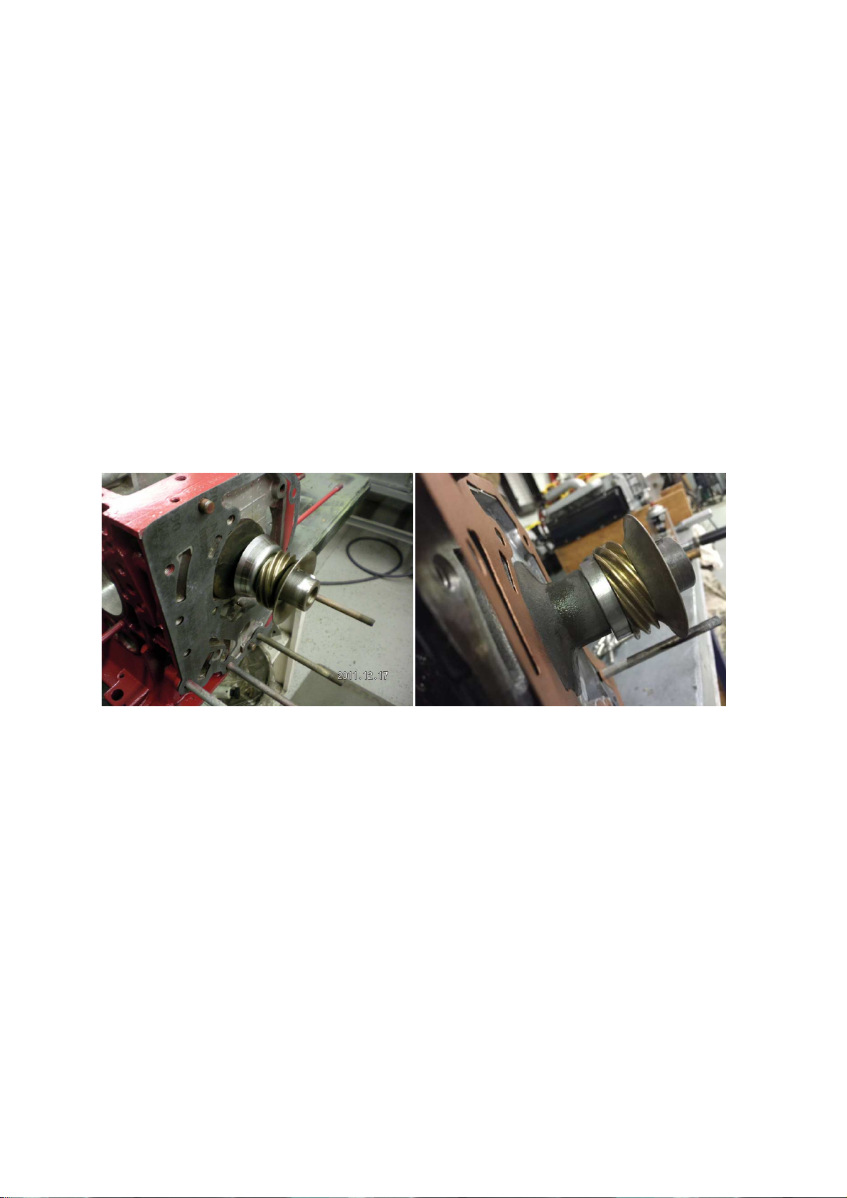
Drive Gear Installation:
The distributor drive gear and slinger need to be installed before the accessory
housing. This assembly is made up of four pieces and need to be in the right order
and orientation. The photos below show the order and the assembled unit. (Fig 1)
Use a large socket or pipe to lightly drive these pieces over the crankshaft end.
The order is…eccentric, spacer, gear, and slinger (facing out). Some engines may
be equipped with the wider spacer that eliminates the concentric and small spacer.
(Fig 1b) Be sure the woodruff keys are installed properly onto the crankshaft prior
to installation.
Fig 1. Rear gear parts installed on the crankshaft Fig 1b.
Housing Installation
Apply an even coat of copper spray on both sides of the rear gasket. Once it is
tacky install onto the case. Slide the Accessory housing on and tap into place with
the rubber hammer. Check to see that it has seated all the way around before
installing the hardware. Apply a dab of Loctite onto the threads of the 4 long and 2
short bolts prior to installing them. (Do not install the bolt at the 4 o’clock position
yet. Install three of the four washers and 3/8 nuts onto the studs. Leave the left
one open. (Fig 2) Torque the hardware to the proper specifications. (13 ft/lbs)

Section 4 – 3
Azalea Aviation Copyright 2014
Fig 2. Rear housing installed onto case
Take the alternator stator and install it onto the stator ring using provided Allen screws. Dab a
bit of red Loctite onto end of threads. Place the output wire at the 4 o’clock position. Use the
Adel clamp and the short housing Allen head bolt to secure it. Make sure the stator is flush
against the stator mounting ring. (Figure 3)
Fig 3. – Stator attached and clamp detail
Apply green sleeve Loctite to the rear Puck (inside) and a light coat of Lithium grease to the
outside where the seal will ride. Place onto the end of the crankshaft and using a dead blow
hammer tap into place. Install the large washer and bolt using red Loctite and torque to 50 -60

Section 4 – 4
Azalea Aviation Copyright 2014
foot lbs. (Figure 4) Use a wooden block against the #1 crankshaft rod journal to hold the
crankshaft in place while torquing.
Fig 4 – Rear Puck installed and Torqued
The Rear drum can be put onto the puck loosely until the ring gear and starter are installed. Be
sure the drum is clean on the inside. Because it is made up of magnets it can attract small filings.
Notice that there may be a positioning pin on the puck and a hole in the drum. This is to ensure
that the TDC mark on the drum is in the proper location. Otherwise turn the crankshaft until the
#1 rod journal is at the TDC position and make sure the mark on the alternator drum in near the
timing marks on the housing.

Section 5 - 1
Azalea Aviation Copyright 2014
Starter Installation
Tools Required:
/16” Hex socket
Torque wrench
17 mm wrench
9/16” socket
Sealants Required:
Copper spray
Pipe Sealant
Red Loctite
Parts Required:
Case with Rear Alternator attached
Oil Cover Plate and hardware
Starter
Ring Gear
Lower Starter bracket and hardware
Oil Cooler block off and hardware

Section 5 - 2
Azalea Aviation Copyright 2014
Installing Oil Cover Plate
Spray copper spray onto both sides of the oil cover gasket. Once it is tacky, place
onto the case and bolt the cover plate into position. Torque the bolts to 150 “ lbs
or 1 foot lbs. Spray copper spray onto the block off plate gasket and bolt the
block off into place with same torque. (Figure 1, Figure 2)
Fig 1. Oil Cover in Place
Install the ring gear and loosely snug up the six bolts. Install the starter and check
for fit. Check the clearance on the ring gear to bendix gear on the starter. Have
at least a 1/8” space. Adjustments can be made by placing a washer under the
top starter bolt. The top of the gear should be in line with the “flat” spot on the
starter nose. (Figure ) Tighten the main starter bolt with it in this position. If
you are installing a new starter kit the Lower Bracket may need to be drilled and
fitted to hold the starter in place. Remove the ring gear and bolt the Starter and
lower bracket into position using Loctite on the bolts/nuts. (Figure 4) Reattach
the Ring gear using red Loctite on the bolts and torquing to 0 ’lbs.

Section 5 -
Azalea Aviation Copyright 2014
Fig. 2 – Block Off Plate Installed
Fig. – Ring gear to Bendix clearance

Section 5 - 4
Azalea Aviation Copyright 2014
Fig. 4 – Lower Bracket bolted in place.
Fig. 5 – Starter and Ring Gear Finally Bolted
Be sure to rotate the crankshaft and check for clearance and interference. Pulses
felt during the rotation that is caused by the magnets in the alternator. Onto the
next step!

Section 6 - 1
Azalea Aviation Copyright 2014
Piston/Cylinder and Rod Assembly
Piston and Connecting Rod
Tools Required:
Wrist pin tool
Propane torch or equivalent
Vise
Sealants:
Oil
Parts Required:
Rebuilt or new Connecting rods (6)
Set of New Forged Pistons (6)
Fig 1 – Tools and Parts
Inspect condition and quality of parts (Fig 1)
Clamp the #1 Connecting rod in the vise with the numbers “up”. Use wooden
blocks or aluminum angles in the vise to protect the connecting rod. (Fig 2) If the
connecting rod nuts are tightened, loosen them at this time. Remove the wrist pin
from the piston, lubricate it lightly with oil and reinsert it to check for freedom of

Section 6 - 2
Azalea Aviation Copyright 2014
movement in the piston. Slide the wrist pin partially out of the piston allowing
room for the rod. Insure the orientation at which the piston will be installed onto
the connecting rod. Practice installing the pin properly while the rod is cool
because once you heat it up and install it you have one chance to get it right
without having to use a press.
The piston has an arrow marking on the top which should always point to
the propeller or flange end on the engine. In the case above with rod #1 the arrow
will point to the right. On rod #2 it will point to the left, and so on. Using the torch
slowly heat up the small end of the rod until it starts to turn a light brownish color.
(Fig 3) Quickly insert the piston (in correct orientation) and slide the wrist pin it
until it hits the guide. Hold this position for a few seconds as the rod cools down
and locks the wrist pin in place. (Fig 4) Check for freedom of movement of the
piston. The wrist pin should be centered on the rod. If the pin locks in off center
then a press may be needed to move the pin. Be very careful using a press to not
damage the piston.
Remove the Piston/Rod from the vise once cool and proceed to the next set. Do not
slap the rod against the piston skirt at any time. Always check the arrow direction
on the pistons that they correspond correctly to the numbered rod and installation.
Fig. 2 – Rod Clamped into vise

Section 6 - 3
Azalea Aviation Copyright 2014
Fig. 3 – Heating up Rod small end (brownish color)
Fig. 4 – Inserting Rod pin using tool – quickly and smoothly

Section 6 - 4
Azalea Aviation Copyright 2014
Piston Ring and Cylinder Assembly
Tools Required:
Piston ring installation tool
Dead blow hammer
Cylinder/piston assembly tool
Piston Ring Compressor
Sealants:
Oil (in container)
Parts Required:
Piston/connecting rod assembly (6)
Piston Ring set (Hastings Chrome)
Rebuilt cylinders or new (6)
Inspect the condition and quality of all the parts for this step. Be sure that the
cylinders are matching the bore of the pistons and rings. Look at the hone work
inside the cylinders for a consistent 45 degree crosshatch. The cylinder should be
cleaned and painted on the fins. The rods should be balanced, stock forged stroker
rods with ARP bolts or new forged rods (available through Azalea Aviation).
This manual suits for next models
1
Table of contents
Popular Engine manuals by other brands

Perkins
Perkins 2806D-E18TA Operation and maintenance manual

Westerbeke
Westerbeke 33a specification

CHEE SIANG INDUSTRIAL
CHEE SIANG INDUSTRIAL M100 Series instruction manual

Kubota
Kubota D1005-E3 Operator's manual

Oldsmobile
Oldsmobile V-8 1971 manual

Briggs & Stratton
Briggs & Stratton 120000 Service, troubleshooting, and repair manual

Detroit Diesel
Detroit Diesel MBE 900 Technician guide

Bosch
Bosch Rexroth IndraDyn T Project planning manual

Selve
Selve SE Plus 1/6 Operating instruction

Beckhoff
Beckhoff AS2000 Series operating instructions

ARVEN
ARVEN OP Series Operating instruction

Briggs & Stratton
Briggs & Stratton Sno/Gard 222400 Series Operating and maintenance instructions