ZSSC5101
Evaluation Kit Description
Kit Description
April 17, 2015
© 2015 Zentrum Mikroelektronik Dresden AG —Rev. 1.00
All rights reserved. The material contained herein may not be reproduced, adapted, merged, translated, stored, or used without the
prior written consent of the copyright owner. The information furnished in this publication is subject to changes without notice.
4.5.2. Checking the Calibrated Angle .........................................................................................................19
4.5.3. Indication of Possible Errors during Programming ...........................................................................19
4.6. Selecting the Slope of the Angle Calibration and Writing the Settings ...................................................19
4.7. “Digital Out” Tab ......................................................................................................................................20
4.8. “Analog Out” Tab .....................................................................................................................................21
4.9. “Memory” Tab ..........................................................................................................................................23
4.9.1. Loading and Saving EEPROM Settings ...........................................................................................24
4.10. Diagnostics Conditions............................................................................................................................24
5Related Documents........................................................................................................................................25
6Glossary .........................................................................................................................................................25
7Document Revision History............................................................................................................................25
List of Figures
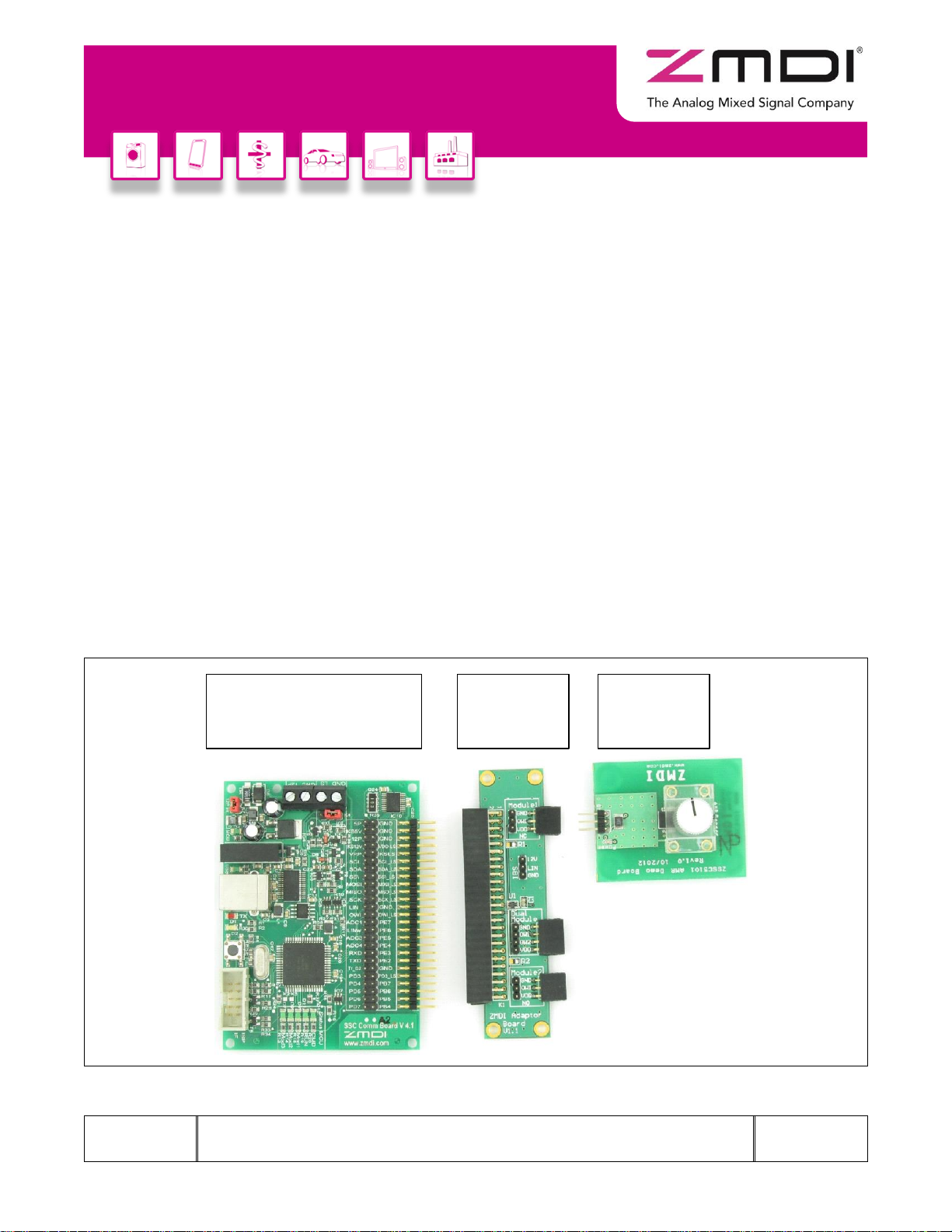
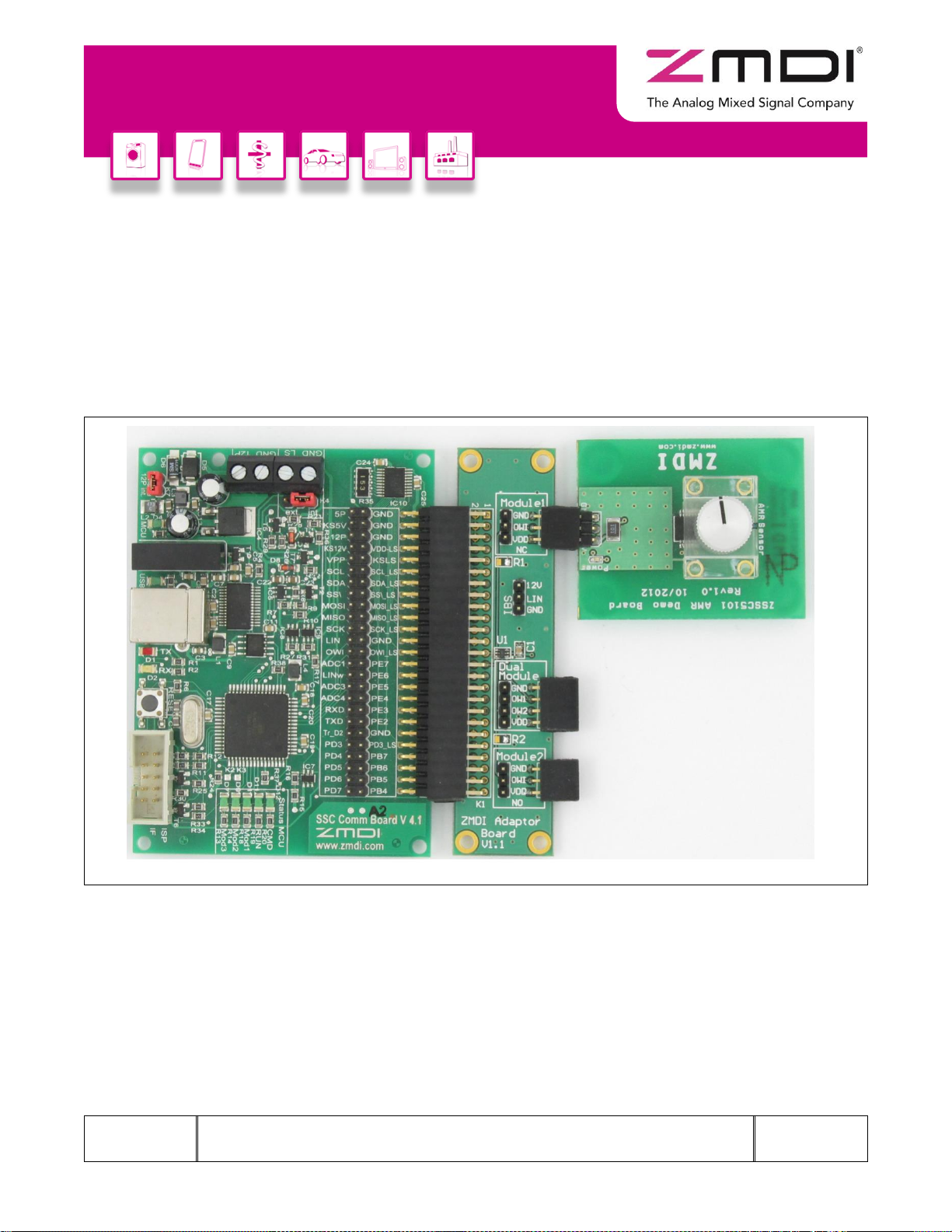
Figure 1.1 ZSSC5101 Evaluation Kit Boards.......................................................................................................5
Figure 2.1 Default Hardware Set-up ....................................................................................................................7
Figure 3.1 Example of Properties for a USB Serial Converter under the Device Manager.................................8
Figure 3.2 Updating the Driver for the Communication Board (FT232R USB UART under Device Manager) ...9
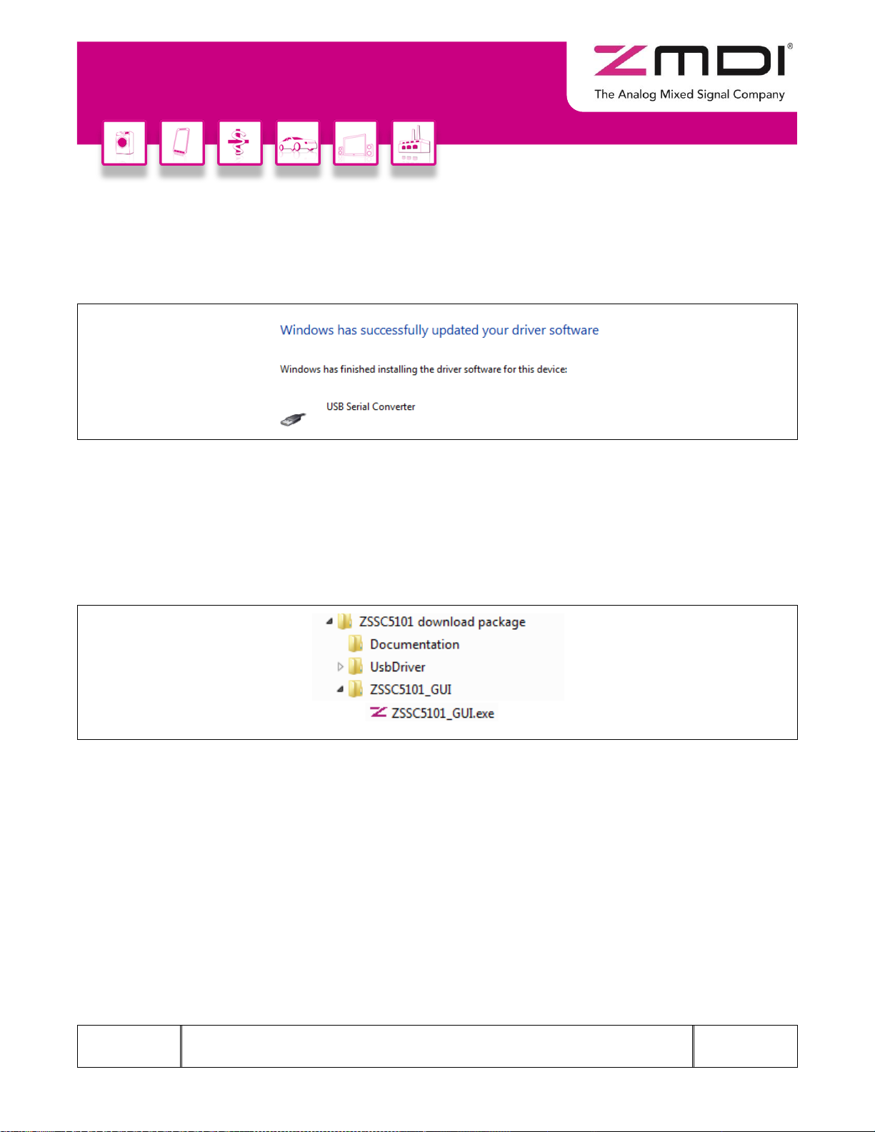
Figure 3.3 Location of the FTDI Driver in the ZSSC5101 Evaluation Software Directory ...................................9
Figure 3.4 Confirmation Message after Installing FTDI Driver...........................................................................10
Figure 3.5 Location of the ZSSC5101 Evaluation Software ..............................................................................10
Figure 4.1 “Setup” Tab .......................................................................................................................................11
Figure 4.2 “Setup” Tab Example with Module 1 Selected .................................................................................12
Figure 4.3 “ADC and Offset Calibration” Screen ...............................................................................................13
Figure 4.4 Example Graph and Max/Min Values for Module 1..........................................................................14
Figure 4.5 “Start Calibration Check” ..................................................................................................................15
Figure 4.6 Check Boxes for Error Estimation.....................................................................................................15
Figure 4.7 Estimated Error Display....................................................................................................................15
Figure 4.8 “Read Angle” Screen ........................................................................................................................16
Figure 4.9 “Angle Calibration” Screen................................................................................................................17
Figure 4.10 Setting the Angle Range with the “Angle Calibration” Tab ...............................................................18
Figure 4.11 Clamping Values...............................................................................................................................18
Figure 4.12 Angle Calibration Check Example...................................................................................................19
Figure 4.13 Error Condition Indication Example..................................................................................................19
Figure 4.14 “Slope Direction” Menu and “Write settings” Button on the “Setup” Tab ..........................................19
Figure 4.15 “Digital Out” Screen ..........................................................................................................................20
Figure 4.16 “Analog Out” Screen Example ...........................................................................................................21
Figure 4.17 “Analog Out” Screen Example with Two Modules............................................................................22
Figure 4.18 “Memory” Screen ..............................................................................................................................23
Figure 4.19 Saving or Loading Files for EEPROM Settings................................................................................24