ZonarSound MP600x600 User manual

Installation Manual
Product Overview1.
The ZonarSound ‘Drop-in’ speaker panels are flat, directional loudspeakers that have been
designed to drop into a standard 600mm x 600mm suspended ceiling grid. Each speaker
panel provides a high-quality, directional output to a specific listening zone with minimal
overspill into surrounding areas. The speaker panels are based on the flat, flexible speaker
technology developed and patented by Warwick Audio Technologies Ltd.
The speaker panels operate in a Master/Slave mode and only require an audio signal input
and power supply to the Master panel. Speaker panels can be connected in a daisy chain or
star configuration (or a combination of both). The Master speaker panel requires a low voltage
balanced or unbalanced audio input.
A separate, shelf mounted, amplifier is available as an alternative to the amplifier in the
Master panel.
The ZonarSound System
Ref: WAT02360213
Issue: 01
ZonarSound
The Venture Centre, Sir William Lyons Road, Coventry CV4 7EZ

Page 2
The ZonarSound System
Installation Manual Issue 01
Contents
1. Product Overview 1
2. Important Safety Information 3
3. Product Configurations 4
3.1 Master and Slave Speaker Panels (Line Level Audio Source) 4
3.2 Configuration Options 4
3.3 DCLA 100 with Slave Speaker Panels (LL Audio Source) 5
4. Installing Speaker Panels 6
4.1 Preparing the Speaker Panel Support 6
4.2 Fitting the Speaker Panels 7
4.3 Connecting and Configuring the Speaker Panels 7
5. Connecting and Setting the DCLA 100 AMP Box 13
5.1 Connecting the Amplifier 13
5.2 Setting up the Sound Balance 14
5.3 Indicators 14
6. Declaration of Conformity 15
7. Technical Specifications 16

2.
1. Warning! High voltages are present inside the speaker panels and DCLA100
Amplifier.
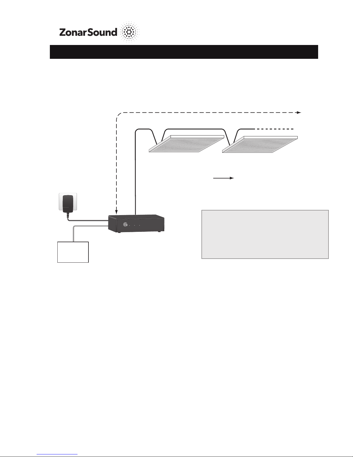
2. The ZonarSound system components must only be used with a Class II Power Supply.
3. Always disconnect the ZonarSound components from the power source before making
or removing any connections.
4. Read all documentation before operating the equipment.
5. Equipment should be installed and serviced by a skilled person only.
6. All high voltage cabling to speakers must be double insulated (e.g. Def Stan 61-12 part 4).
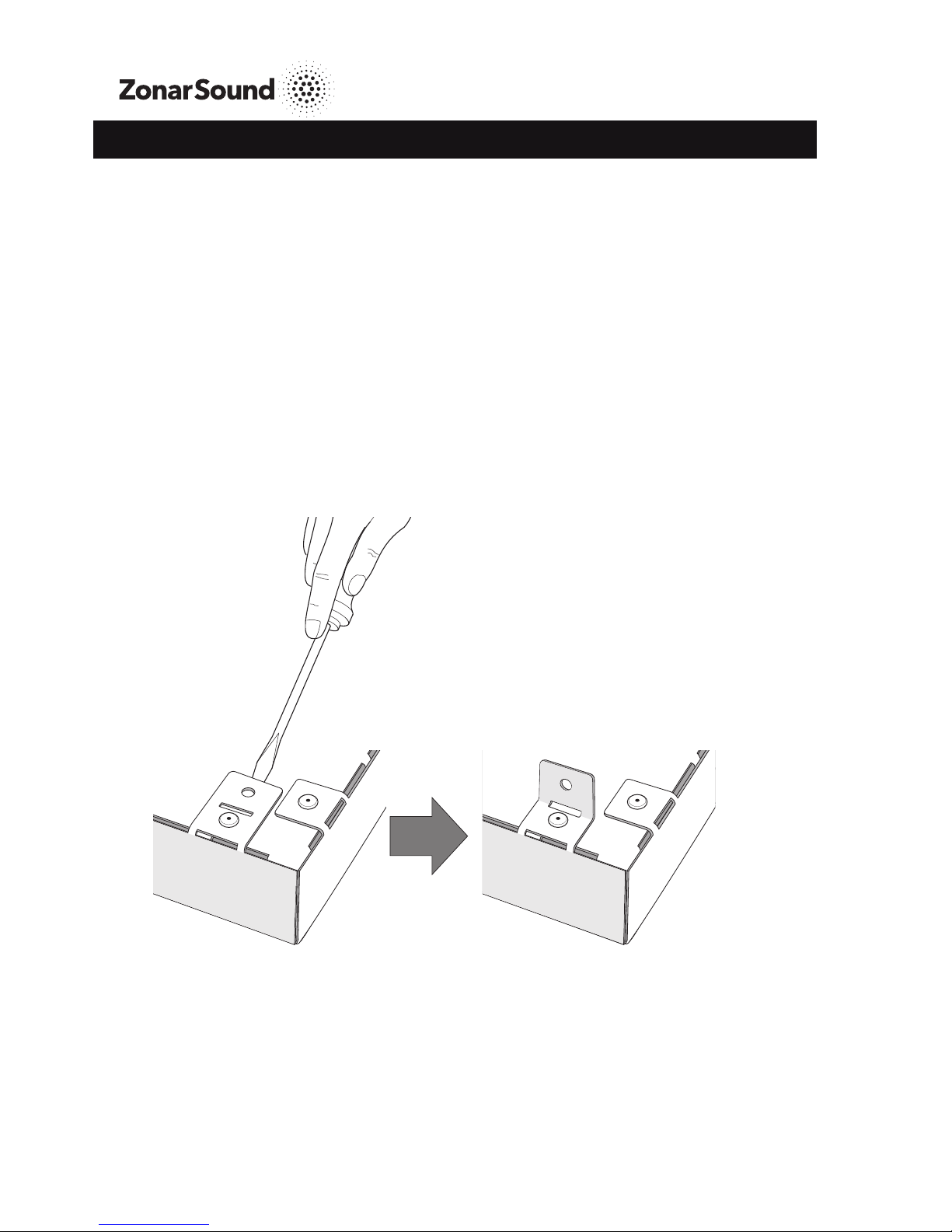
7. Ensure that the product is adequately supported in the ceiling grid.
Additional wire/cable (e.g http://www.reutlinger.de) may be required
8. Ensure that appropriate cabling is used to provide at least 22Vdc at the input to the
ZonarSound system from a 24VDC supply.
9. The devices are designed for internal use only. Do not fit the units near heat or moisture
sources.
10. Ensure all connections and cables are adequately secured.
11. Ensure cables are not trapped between speaker panel and ceiling grid.
12. It is not recommended to exceed the specified input signal levels.
13.The product label is located on the loudspeaker rear plate.
14. Sound pressure levels in excess of 85dBA can cause hearing loss. Ear defenders are
recommended in test conditions.
15. Do not block the ventilation slots in the remote amplifier.
16. Do not disassemble the speaker panel. This may disturb the fire protection materials
present in the panel.
17. Ensure stable and suitable apparatus is available to climb on to install panels in ceiling
grid.
Page 3
The ZonarSound System
Installation Manual Issue 01
Important Safety Information

Page 4
The ZonarSound System
Installation Manual Issue 01
Product Configurations3.
3.1 Master and Slave Panels (Line Level Audio Source)
3.2 Configuration Options
24Vdc
PSU
MP
Audio
Source
LL Audio
MP
LL Audio
24Vdc 24Vdc MP
LL Audio
24Vdc
SP
SP
SP
SP
SP
SP
HV
HV
Maximum overall length = 100m
Maximum length for a balanced signal = 100m
SP
HV
Maximum overall length for
a balanced signal = 100m
Refer to section 4 for installation instructions for these products.
MP SP
Maximum of 3 SPs per MP
HV
Audio
Source
LL Audio
24Vdc PSU
100 metres in total
Key:
LL = Line Level (up to 3V Pk-Pk)
HV = High Voltage Audio (Approx.
300V)
MP = MP 600 x 600 (Master Panel)
Up to 3 MPs can be
daisy chained together
using LL audio and
24Vdc, with the option
to buffer the audio signal
at the MP . To avoid
degradation of sound
quality, the LL audio
must not be buffered
more than twice.
Up to 3 SP’s can be connected to each MP in a star or
daisy chain configuration (or a combination of both).

Page 5
The ZonarSound System
Installation Manual Issue 01
3.3 DCLA 100 with Slave Panels (LL Audio Source)
SP SP
HV
LL Audio
Source
24Vdc PSU
DCLA 100
HV
Volume
Audio Output
Fault
Power
Maximum of 4 SPs per DCLA100
100 metres in total
Refer to section 4 for installation instructions for the speakers. Refer to section 5 for
connections to the DCLA 100.
Key:
LL = Line Level (up to 3V Pk-Pk)
HV = High Voltage Audio (Approx. 300V)
SP = SP 600 x 600 (Slave Panel)

Page 6
The ZonarSound System
Installation Manual Issue 01
Installing Speaker Panels4.
This section describes the installation and setup of the speaker panels, which should only be
carried out by skilled personnel.
Choose a location that allows the audio signal to focus on the intended listening zone and
give consideration to access to the top of the speaker panels.
The speaker panels can be supported by the suspended ceiling framework, but ZonarSound
recommends that additional support is provided for each panel by suspending it from the
roof structure, using a recommended support system (e.g. http://www.reutlinger.de).
4.1 Preparing the Panel Support
Speaker panels come with a suspension anchor point at each corner. Use a wide
flat-blade screwdriver to carefully lever each bracket into a vertical position.
Attach the suspension wires/cables to these anchor points.

Page 7
The ZonarSound System
Installation Manual Issue 01
4.2 Fitting the Speaker Panels
Ensure that all health and safety procedures are followed during the installation of the
•
ZonarSound speaker panel.
Remove the existing ceiling tile.•
Replace it with the ZonarSound speaker panel, ensuring that the panel is correctly seated•
in the ceiling tile grid.
Use a recommended suspension system to attach the panel to the roof structure.•
Note: Avoid supporting the panel in the centre during fitment.
4.3 Connecting and Configuring the Speaker Panels
4.3.1. Connecting a Standalone Master Panel
When a Master panel is used on its own, it can be connected to the audio source and power
supply unit without removing the amplifier cover plate. Make the connections as shown
below:
AUDIO IN
POWER IN
BUFFERED
AUDIO OUT
+-
+
-
AUDIO OUT
+
-
24V
POWER IN
24V
+-
Neg (-) Black
0V
Pos (+) Red
Connect power and
balanced audio input to
the terminal blocks.
Alternatively, 24V can be
supplied to the standard
‘Power In’ connector.
Note:
For unbalanced audio signals, the
connection is shown below:
AUDIO IN
+
-

Buffered LL
Audio Output
Slave
Speaker
Outputs
Gain Adjust Header
Internal Speaker
Connection
+1
+2
+3
Gain Adjust Header
Amplifier gain setting
(for unbalanced audio):
Header fitted in LO position: 0dB.
Page 8
Each of the connection options are described below:
24 Vdc Out to Next Master Panel
If additional Master panels are to be powered from the
same supply, use the 24Vdc power terminal block. +24Vdc
0v
The ZonarSound System
Installation Manual Issue 01
4.3.2. Connecting Master Panel Outputs
ALWAYS DISCONNECT THE POWER SOURCE BEFORE MAKING OR REMOVING ANY
CONNECTIONS
The inputs to the Master panel are made on the outside of the amplifier cover plate as
described in section 4.3.1. To connect outputs to other Master panels and to Slave panels,
remove the amplifier cover plate by removing the four cover retaining screws. Carefully
lift off the cover and PCB assembly to allow access to the internal connectors. The
terminal blocks are shown in the diagram below:
LL Audio Output

Page 9
The ZonarSound System
Installation Manual Issue 01
4.3.3. Using an Unbalanced Audio Source
*The LL audio output to the next
Master panel (where required) can be
either buffered or un-buffered.
Connect to the appropriate output as
shown.
Note that the overall cable length from
the source (or buffered output) to the
last Master tile must not exceed 10m.
Using a Balanced Audio Source4.3.4.
*The LL audio output to the next
Master (where required) can be either
buffered or unbuffered. Connect to the
appropriate output as shown.
Remember that the overall cable
length from the source (or buffered
output) to the last Master tile must not
exceed 100m.
Unbuffered LL output
to next Master*
Buffered
LL Output
to next
Master*
Amp Gain = 0dB
Move header to HI
position to set Gain
to +6dB Master
HI
LO
Unbuffered LL output
to next Master*
Buffered
LL Output
to next
Master*
Master
HI
LO

Page 10
Remember that the overall cable length to the final Slave must not exceed 100m.
Output
2
Output
3
Internal Speaker
Connection
Master
Output
1
HV Audio Output
to 1 slave panel
Do not connect
Do not connect
Output to 3 slave panels in a daisy
chain or star configuration
(or a combination of both).
Output
2
Output
3
Internal Speaker
Connection
Master
Output
1Do not connect
Do not connect
Output
2
Output
3
Internal Speaker
Connection
Master
Output
1Do not connect
Do not connect
Output to 2 slave
panels in a daisy chain
or star configuration.
The ZonarSound System
Installation Manual Issue 01
4.3.5. Connecting the Master Panel Output to Slave Panels
ALWAYS DISCONNECT THE POWER SOURCE BEFORE MAKING OR REMOVING ANY
CONNECTIONS
When connecting Slave panels to the Master panel, lift off the output terminal block housing
and move it to a pair of output pins that corresponds with the number of Slave panels to be
used. Always select the correct output for the number of Slave panels.
Never connect to more than one output connector.

Page 11
The ZonarSound System
Installation Manual Issue 01
Remove the four cover retaining screws from the Slave panel and carefully lift off the cover
and PCB assembly to allow access to the internal connectors. Connect the HV signal as
shown below:
Internal Speaker
Connection
Slave
Loop (HV Out)
Amp (HV In)
Star Connection
Two audio signal connectors enable
daisy-chain or star configuration.
Edge
Clamper
Once all internal cable connections have
been made to Master and Slave panels,
secure them by pushing them into the edge
clamper located in the recess at the side of
the amplifier cover plate:
The amplifier cover plate/PCB assembly can
now be re-fitted.
Once all connections have been made and
the cover plate refitted, use a cable tie to
secure all cables to the cable tie anchor point:
Cable Tie
Anchor Point

Page 12
The ZonarSound System
Installation Manual Issue 01
Setting the Sound Level4.3.6.
The Master volume control for each amplifier is
located on the upper face of the Master panel.
Once the audio source and all panels have been
powered up, the Master volume control can be
used to set the volume of the Master panel as well
as setting the maximum volume for the connected
Slave panels. Use a trim adjust tool (see below) to
adjust the volume on the upper face of the Master
panel.
For all panels to produce the same volume,
the secondary volume controls located on the
upper face of each Slave panel should be set
to 0dB.
The volume output of an individual Slave panel
can be set lower than the Master by
adjusting its volume control. The Slave panel can
never be louder than the Master panel.
4.3.7. Indicators
The LED indicators on the upper face of the Master panel are as follows:
Name Colour Function
Audio Blue Flashes in sync with the incoming audio.
Increases in overall brightness with higher audio levels.
Will not be illuminated whenever OUTPUT FAULT LED is illuminated.
Power Green Illuminated when power is supplied to the unit and switched ON.
Output
Fault
Red Will illuminate whenever a fault (short circuit) is detected at the HV
output.
Illuminates for approx. 10 seconds and will then go out.
If the fault persists, the LED will illuminate again and the cycle will
be repeated until the fault is removed.
VOLUME
+
-
www.zonarsound.com
VOLUME
-15dB
-6dB
-9dB
-12dB
-3dB
0dB
Trim Adjust Tool

From
PSU
To first
Slave panel
From LL
audio source
24V 0V
POWER IN
MONO
OUTPUT
O/P COM
Serial No.
www.zonarsound.com
WARNING: HIGH VOLTAGE INSIDE
REFER TO MANUAL & DISCONNECT POWER
BEFORE REMOVING COVER. NO USER
SERVICEABLE PARTS INSIDE. ONLY TO
BE SERVICED BY QUALIFIED PERSONNEL
STEREO INPUT
!
+-
24V
POWER IN
FIT TERMINAL COVER BEFORE POWERING UP !
DCLA100
Page 13
The ZonarSound System
Installation Manual Issue 01
Connecting and Setting the DCLA 100 AMP
5.
5.1 Connecting the Amplifier
The DCLA 100 Amplifier is used in place of a Master panel amplifier to produce the HV
output required by Slave panels. The Amplifier can be placed in a location close to the audio
source, and it’s HV output can drive up to four Slave panels connected in a daisy chain. The
DCLA 100 mixes a stereo line level input to provide a mono HV output.
Connect the DCLA 100 Amplifier as follows:
The Amplifier rear panel provides two means of connecting a 24Vdc supply, i.e a dc power
socket and also terminals on the terminal connector strip. Note that whichever power input
connection is used, 24Vdc is not available at the unused ‘Power In’ connector.
Before powering up the amplifier, refit
the terminal cover and set the number of
connected Slave panels on the underside of
the Amplifier box:

Page 14
The ZonarSound System
Installation Manual Issue 01
5.2 Setting the Sound Level
Power
Audio Output
Fault
Volume
Once the audio source has been connected and the DCLA 100 has been powered, the
volume control located on the front of the DCLA 100 sets the volume for all Slave panels.
To ensure that all panels produce the same
Volume,the switched volume control, located on
the upper face of each Slave panel, should be
set to 0dB.
The volume of an individual Slave panel can be
set lower than the amplifier output by adjusting
its switched volume control. The Slave panel
can never be louder than the volume set on the
master volume control.
5.3 Indicators
The LED indicators on the front of the Amplifier box are as follows:
Name Colour Function
Audio Blue Flashes in sync with the incoming audio.
Increases in overall brightness with higher audio levels.
Will not be illuminated whenever OUTPUT FAULT LED is illuminated.
Output
Fault
Red Will illuminate whenever a fault (short circuit) is detected at the HV
output.
Illuminates for approx. 10 seconds and will then go out.
If the fault persists, the LED will illuminate again and the cycle will be
repeated until the fault is removed.
Power Green Illuminated when power is supplied to the unit and switched ON.
www.zonarsound.com
VOLUME
-15dB
-6dB
-9dB
-12dB
-3dB
0dB

EC Declaration of Conformity
In accordance with BS EN ISO/IEG 17050-1:2004
We: Warwick Audio Technologies Ltd
Of: The Venture Centre, Sir William Lyons Road, Coventry, CV5 7EZ, UK
declare that:
Equipment: ZonarSound ceiling tiles and amplifier
Model name/numbers: MP600x600, SP600x600, DCLA 100
The following CE Marking Directives are applicable:
2006/95/EC Conforms with the safety objectives of the Low Voltage Directive and
its amending Directives
2004/108/EC Conforms with the essential protection requirements of the
Electromagnetic Compatibility Directive and its amending Directives
and has been designed and manufactured to the following standards:
EN 60065:2002+A11:2008
Audio, video and similar electronic apparatus - Safety requirements
EN 55013:2001 + A1:2003 + A2:2006
Sound and television broadcast receivers and associated equipment - Radio disturbance
characteristics - Limits and methods of measurement
EN 55020:2007
Sound and television broadcast receivers and associated equipment – Immunity
characteristics - Limits and methods of measurement
I hereby declare that the equipment named above has been tested and found to comply with the
relevant sections of the above referenced specifications. The unit complies with all essential
requirements of the Directives.
Signed by: ………………………………………
Name: David Hoare
Position: Engineering Manager
13
Warwick Audio Technologies Ltd
On: …………….…………………………….
Page 15
The ZonarSound System
Installation Manual Issue 01
Declaration of Conformity6.
20 Mar. 2013

DCLA 100 Amplifier
Dimensions (mm) 190 x 150 x 52
Audio input connection RCA-Phono Stereo
Panel volume control 0dB to Max SPL
Input gain selection +6dB Internal jumper selection (Unbalanced only)
Audio IN 1V RMS Recommended level
Supply voltage 24V dc (absolute minimum = 22V dc)
LED’s Power On, Output Fault, Audio
Electrical power requirements
(running)
LED’s Power On, Output Fault, Audio
Slave Panel volume control -15 to 0 In 3 dB steps
Max distance from Master or DCL 100
to Slave
7.
Parameter Value
Master Panel (MP600x600) and Slave Panel (SP600x600)
Dimensions (mm) 595 x 595 x 30
Panel weight 5.5 kg
Max SPL 90 dB @ 2 kHz @ 2 m @ 1 V RMS input.
THD <5% @ 85 dB @ 2 m
Master audio input connection Screw Terminal (Balanced or un-balanced)
Master Panel volume control 0dB to Max SPL
Master Panel input gain selection +6dB Internal jumper selection (Unbalanced only)
Master Panel audio IN 1V RMS Recommended level
Supply voltage 24V dc (absolute minimum = 22V dc)
Electrical power requirements
(running)
Page 16
The ZonarSound System
Installation Manual Issue 01
Technical Specifications
6W (250 mA) with Master tile plus 3 slave tiles
Electrical power requirements
(start-up)
1A 24 V dc
100m(using2wocorecable<20Ωloop,<10nFper
100m (440v rated) (e.g. Def Stan 61-12 part 4))
6W (250 mA) with 4 slave tiles
Electrical power requirements
(start-up) 1A 24 V dc
Operating temperature -10oto +40o
Storage temperature -40oto +70o
This manual suits for next models
2
Table of contents