JBL SCS160SI User manual

SCS160
SURROUND CINEMA
SPEAKERS
OWNER’S GUIDE

2
READ FIRST!
Important Safety Precautions!
1. Read these instructions.
2. Keep these instructions.
3. Heed all warnings.
4. Follow all instructions.
5. Do not use this apparatus near
water.
6. Clean only with a dry cloth.
7. Do not block any ventilation open-
ings. Install in accordance with the
manufacturer’s instructions.
8.
Do not install near any heat sources
such as radiators, heat registers,
stoves or other apparatus (including
amplifiers) that produce heat.
9. Do not defeat the safety purpose of
the polarized or grounding-type plug.
A polarized plug has two blades with
one wider than the other. A ground-
ing-type plug has two blades and a
third grounding prong. The wide
blade or the third prong are provided
for your safety. If the provided plug
does not fit into your outlet, consult
an electrician for replacement of the
obsolete outlet.
10. Protect the power cord from being
walked on or pinched, particularly at
plugs, convenience receptacles and
the point where they exit from the
apparatus.
11. Only use attachments/accessories
specified by the manufacturer.
12. Use only with the cart, stand, tri-
pod, bracket or table specified by the
manufacturer or sold with the appa-
ratus. When a cart is used,
use caution when moving
the cart/apparatus combi-
nation to avoid injury from
tip-over.
13. Unplug this apparatus during light-
ning storms or when unused for long
periods of time.
14. Refer all servicing to qualified
service personnel. Servicing is
required when the apparatus has
been damaged in any way, such as
power-supply cord or plug is dam-
aged, liquid has been spilled or
objects have fallen into the appara-
tus, the apparatus has been exposed
to rain or moisture, does not operate
normally, or has been dropped.
15. Do not use attachments not
recommended by the product
manufacturer, as they may cause
hazards.
16. This product should be operated
only from the type of power source
indicated on the marking label. If you
are not sure of the type of power sup-
ply to your home, consult your prod-
uct dealer or local power company.
For products intended to operate from
battery power, or other sources, refer
to the operating instructions.
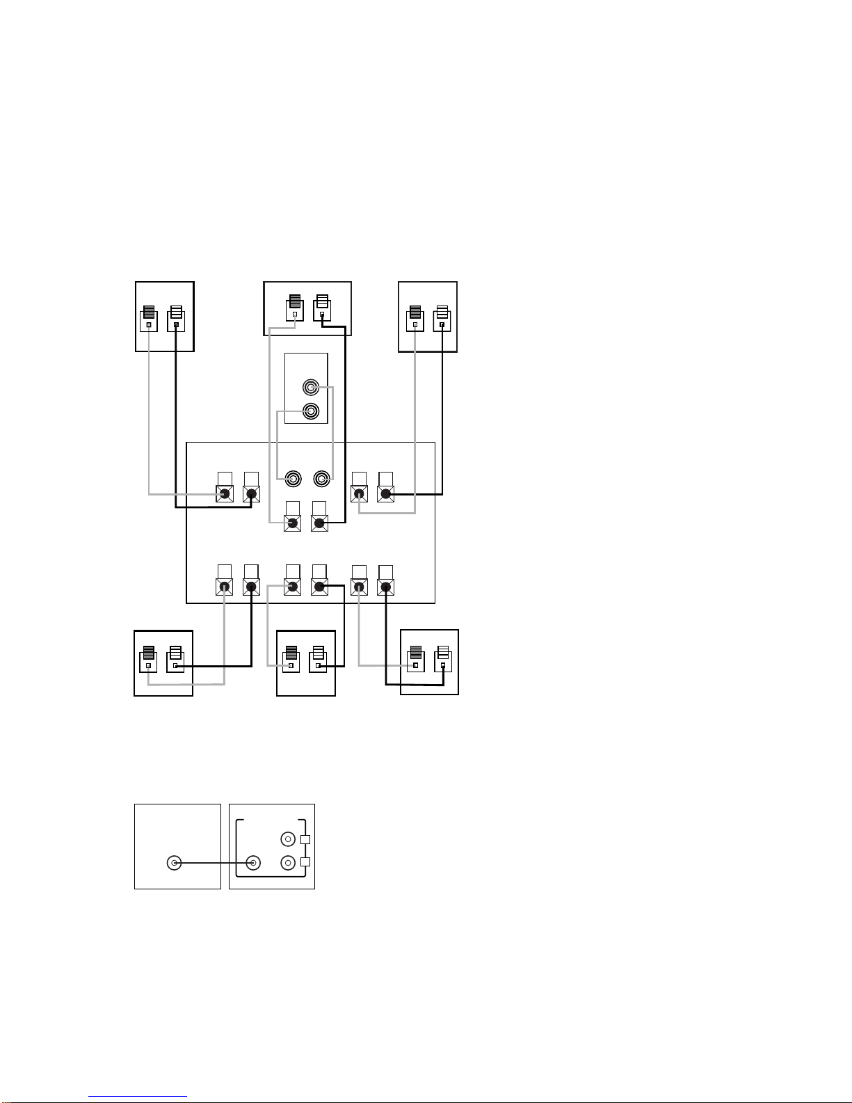
17. If an outside antenna or cable
system is connected to the product,
be sure the antenna or cable system
is grounded so as to provide some
protection against voltage surges and
built-up static charges. Article 810 of
the National Electrical Code, ANSI/
NFPA 70, provides information with
regard to proper grounding of the
mast and supporting structure,
grounding of the lead-in wire to an
antenna discharge unit, size of
grounding conductors, location of
antenna-discharge unit, connection
to grounding electrodes, and require-
ments for the grounding electrode.
See Figure A.
18. An outside antenna system should
not be located in the vicinity of over-
head power lines or other electric
light or power circuits, or where it
can fall into such power lines or cir-
cuits. When installing an outside
antenna system, extreme care should
be taken to keep from touching such
power lines or circuits, as contact
with them might be fatal.
19. Do not overload wall outlets,
extension cords, or integral conve-
nience receptacles, as this can result
in a risk of fire or electric shock.
20. Never push objects of any kind
into this product through openings, as
they may touch dangerous voltage
points or short-out parts that could
result in a fire or electric shock.
Never spill liquid of any kind on the
product.
21. Do not attempt to service this
product yourself, as opening or
removing covers may expose you to
dangerous voltage or other hazards.
Refer all servicing to qualified service
personnel.
22. When replacement parts are
required, be sure the service tech-
nician has used replacement parts
specified by the manufacturer or that
have the same characteristics as the
original part. Unauthorized substitu-
tions may result in fire, electric shock
or other hazards.
23. Upon completion of any service
or repairs to this product, ask the
service technician to perform safety
checks to determine that the product
is in proper operating condition.
24. The product should be mounted
to a wall or ceiling only as recom-
mended by the manufacturer.
CAUTION
RISK OF ELECTRIC SHOCK
DO NOT OPEN
CAUTION: To prevent electric shock,
do not use this (polarized)
plug with an extension cord,
receptacle or other outlet
unless the blades can
be fully inserted to
prevent blade exposure.
The lightning flash with arrowhead symbol,
within an equilateral triangle, is intended to
alert the user to the presence of uninsulated
“dangerous voltage” within the product’s
enclosure that may be of sufficient magnitude to constitute a
risk of electric shock to persons.
The exclamation point within an equilateral
triangle is intended to alert the user to the
presence of important operating and
maintenance (servicing) instructions in the
literature accompanying the appliance.
Antenna Lead-In Wire
Ground Clamp
Antenna Discharge Unit (NEC Section 810-20)
Grounding Conductors (NEC Section 810-21)
Electric Service Equipment
Ground Clamps
Power Service Grounding Electrode System
(NEC Art. 250, Part H)
Figure A.
Example of Antenna Grounding as
per National ElectricalCode
ANSI/NFPA 70

3
INCLUDED
THANK YOU FOR CHOOSING JBL
For more than 50 years, JBL
has been involved in every
aspect of music and film
recording and reproduction,
from live performances to
the recordings you play in
your home, car or office.
We’re confident that the JBL
system you have chosen will
provide every note of enjoy-
ment that you expected –
and that when you think
about purchasing additional
audio equipment for your
home, car or office, you will
once again choose JBL.
Please take a moment to
register your product on our
Web site at www.jbl.com.
It enables us to keep you
posted on our latest advance-
ments, and helps us to better
understand our customers
and build products that
meet their needs and
expectations.
JBL Consumer Products
Five satellites for left, right and
surrounds. Wall-mount brackets.
One center channel speaker
with adjustable support leg.
Powered subwoofer.
Two 20' speaker cables for
connection from receiver to
subwoofer.
Two 15' speaker cables for
connection from subwoofer
to front speakers.
Four 40' speaker cables for
connection from receiver to
three rear satellites and
center speaker.

4
SPEAKER PLACEMENT
SUBWOOFER
SURROUND SPEAKERS
5 – 6 ft
FRONT
SPEAKERS
0-2 ft
The front speakers should be
placed the same distance
from each other as they are
from the listening position.
They should be placed at
about the same height from
the floor as the listeners’
ears will be, or they may be
angled toward the listeners.
The center channel speaker
should be placed slightly
behind the front left and right
speakers, and no more than
two feet above or below the
tweeters of the left and right
speakers. It is often con-
venient to set the center
speaker on top of the tele-
vision set, as shown in the
drawing. Use the supplied
support leg to aim it toward
the listener by screwing the
leg in to angle the speaker
up, or unscrewing the leg
slightly to angle the speaker
down.
Two of the surround speak-
ers should be placed slightly
behind the listening position
and, ideally, should face
each other and be at a level
higher than the listeners’
ears. If that is not possible,
they may be placed on a wall
behind the listening position,
facing forward. The surround
back speaker should be
placed on the wall behind
the listening position, facing
the center channel speaker.
You may leave the surround
back speaker out of your
system altogether if your
receiver/processor only sup-
ports 5.1 channels. The sur-
round speakers should not
call attention to themselves.
Experiment with their place-
ment until you hear a diffuse,
ambient sound accompanying
the main-program material
heard in the front speakers.
The low-frequency material
reproduced by the subwoofer
is mostly omnidirectional,
and this speaker may be
placed in a convenient loca-
tion in the room. However,
bass reproduction will be
maximized when the sub-
woofer is placed in a corner
along the same wall as the
front speakers. Experiment
with subwoofer placement
by temporarily placing the
subwoofer in the listening
position and moving around
the room until the bass
reproduction is best. Place the
subwoofer in that location.
CENTER CHANNEL
SPEAKER

5
MOUNTING OPTIONS
On shelves.
WALL-MOUNTING
On the wall. Wall
brackets are included.
Slide speaker
onto support.
On optional stands (FS400).
Place speaker and
support on wall plate.
Attach plate to wall.
The brackets should be
placed, if possible, so
that the screws will
fasten into a wooden
wall stud. If that is not
possible, use properly
selected wall anchors.
The customer is respon-
sible for proper selection
and use of mounting
hardware, available
through hardware stores,
to properly and safely
wall-mount the speakers.
SATELLITES AND SURROUNDS

6
CONNECTION TIPS
SPEAKER CONNECTIONS
Separate and strip the
ends of the speaker wire
as shown. Speakers and
electronics terminals have
corresponding (+) and (–)
terminals. Most manufac-
turers of speakers and elec-
tronics, including JBL, use
red to denote the (+) terminal
and black for the (–) terminal.
The (+) lead of the speaker
wire is noted with a stripe. It
is important to connect both
speakers identically: (+) on
the speaker to (+) on the
amplifier and (–) on the
speaker to (–) on the amplifier.
Wiring “out of phase” results
in thin sound, weak bass and
a poor stereo image.
With the advent of multi-
channel surround sound
systems, connecting all of
the speakers in your system
with the correct polarity
remains equally important in
order to preserve the proper
ambience and directionality
of the program material.
To connect the supplied
speaker wires to the satellite
and center speaker termi-
nals, press the red or black
plastic tab for the desired
terminal, insert the bare end
of the wire into the hole and
release the tab. Gently tug
on the wire to make sure
that it is fully inserted.
To use the binding-post
speaker terminals on the
subwoofer, unscrew the
colored collar until the pass-
through hole in the center
post is visible under the
collar. Insert the bare end of
the wire through this hole;
then screw the collar down
until the connection is tight.
The hole in the center of each
collar is intended for use
with banana-type connectors.

7
DOLBY* PRO LOGIC* (NON-DIGITAL)
–
SPEAKER LEVEL
Use this installation method
for Dolby Pro Logic applica-
tions (not Dolby Digital, DTS®
or other digital processing),
where the receiver/processor
does not have a subwoofer
output, or a volume-controlled
preamp (line-) level output:
Connect your receiver or
amplifier’s front left and right
speaker terminals to the left
and right terminals on the
subwoofer that are marked
“High Level In.” Connect the
left and right terminals on the
subwoofer that are marked
“High Level Out” to the
corresponding terminals on
the back of your front left
and right speakers.
Connect your receiver or
amplifier’s center, surround
and surround back speaker
terminals to the correspon-
ding terminals on the back of
your center and surround
speakers.
Right Front
Right Surround
Left Front
Left Surround
Center
+ – + –
+ –
+ –
+ – + –
+ –
Left Front Center
+ –
Left Surround
Right Front
+ –
Right Surround
Surround Back
+ –
+ –
Surround Back
+ –
Subwoofer
Receiver
HIGH LEVEL
+ – – +
L R
OUT
IN

8
DOLBY PRO LOGIC (NON-DIGITAL)
–
LINE LEVEL
Use this installation method
for Dolby Pro Logic appli-
cations (not Dolby Digital,
DTS or other digital process-
ing), where the receiver/
processor is equipped with
a subwoofer output, or a
volume-controlled preamp
(line-) level output:
Use RCA-type patch cords
to connect the line-level sub-
woofer outputs on your
receiver or amplifier to the
line-level inputs on the sub-
woofer. IMPORTANT: Do not
use the LFE input on the sub-
woofer with Dolby Pro Logic
processors. NOTE: If your
receiver or amplifier only has
one subwoofer output jack,
then you will need to use a
Y-connector (not included).
Plug the male end of the Y-
connector into your receiver
or amplifier’s subwoofer out-
put jack, and connect each
of the two female ends to
separate RCA-type patch
cords. Finally, plug the RCA-
type patch cords into the
line-level inputs on the sub-
woofer.
Connect each speaker to
the corresponding speaker
terminals on your receiver
or amplifier.
Make sure your receiver or
processor is correctly con-
figured to indicate that the
subwoofer is “On.”
Note for advanced users: If
your receiver/processor has
a built-in low-pass crossover
filter for the subwoofer out-
put, you may use the LFE
input to bypass the sub-
woofer’s internal crossover.
Use this installation method
for Dolby Digital, DTS or
other digital surround
processors:
Use the line-level input jack
marked “LFE” for the Low-
Frequency Effects channel.
Connect this jack to the LFE
output or subwoofer output
on your receiver or amplifier.
Connect each speaker to the
corresponding speaker
terminals on your receiver
or amplifier.
Make sure that you have
configured your surround
sound processor for
“Subwoofer On.” The
receiver should be config-
ured for 6.1-channel opera-
tion (if available), and the
front left, front right, center
and rear speakers should all
be set to “Small.” If your
receiver allows you to set
the crossover frequency
between the subwoofer and
the main speakers, select
120Hz or the setting that is the
closest frequency below it.
DOLBY DIGITAL OR DTS
(OR OTHER DIGITAL SURROUND MODE) CONNECTION
LINE LEVEL IN
LFE INPUT
LFE OUT
L
R
SUBWOOFERRECEIVER
+ –
+ –
+ –
+ –
+ –
+ –
+ –
+ –+ –
Receiver
Subwoofer
Out
Left
Front
Left
Surround + –
Right
Front
Right
Surround
Subwoofer
R L
Center
Surround Back
Line-
Level In
Right Surround
Right Front
Left Surround
Left Front Center
R
L
+ –
Surround Back
+ –

9
OPERATION
MIN MAX
Subwoofer
Level
MIN MAX
Subwoofer
Level
Move the Master Power
switch (marked “Power” ¡)
to the “•” (On) position to
use the subwoofer. The
SCS160 subwoofer will auto-
matically turn on or go into
standby (sleep) mode when
left in the auto mode (“Auto/
On” switch ™in the “Auto”
position). When your
receiver or amplifier is off,
or is not sending program
material to the subwoofer,
the subwoofer will be in
standby mode (LED will be
red). When the subwoofer
senses an audio signal, it will
automatically turn on (LED
will be green). If the sub-
woofer does not sense a sig-
nal after approximately 20
minutes, it will automatically
go back into standby mode.
When the “Auto/On” switch
™is switched to the “On”
position, the subwoofer will
remain on, whether or not
program material is playing.
If you will be away from
home for an extended period
of time, or if the subwoofer
will not be used, switch the
Master Power switch ¡to
the Off position.
VOLUME
POWER
HIGH LEVEL
+ – – + SUBWOOFER
LEVEL
OUT
IN
L R LINE LEVEL IN
LFE
L
R
AUTO ON
MIN MAX
SUB 160
£
¡
™
IMPORTANT: CONNECT STRIPEDWIRE TO RED ( ) SPEAKER TERMINAL.
GREEN: ON
RED: STANDBY
+
A Harman International Company
JBL, Incorporated
Volume may be adjusted
using the Subwoofer Level
control £as shown.

10
If there is no sound from any
of the speakers:
• Check that receiver/ampli-
fier is on and a source is
playing.
• Check that the powered
subwoofer is plugged in,
and its
Power switch ¡is
switched on (“•” position).
• Check all wires and con-
nections between receiver/
amplifier and speakers.
Make sure all wires are con-
nected. Make sure none of
the speaker wires are
frayed, cut or punctured, or
touching each other.
• Review proper operation of
your receiver/amplifier.
If there is no sound coming
from one speaker:
• Check the “Balance” control
on your receiver/amplifier.
• Check all wires and con-
nections between receiver/
amplifier and speakers.
Make sure all wires are con-
nected. Make sure none of
the speaker wires are
frayed, cut or punctured, or
touching each other.
• In Dolby Digital or DTS
modes, make sure that the
receiver/processor is config-
ured so that the speaker in
question is enabled.
• Turn off all electronics
and switch the speaker in
question with one of the
other speakers that is work-
ing correctly. Turn every-
thing back on, and deter-
mine whether the problem
has followed the speaker, or
has remained in the same
channel. If the problem is
in the same channel, the
source of the problem
is most likely with your
receiver or amplifier, and
you should consult the
owner’s manual for that
product for further informa-
tion. If the problem has fol-
lowed the speaker, consult
your dealer for further assis-
tance or, if that is not possi-
ble, visit www.jbl.com for
further information.
If there is no sound from the
center speaker:
• Check all wires and con-
nections between receiver/
amplifier and speaker. Make
sure all wires are connected.
Make sure none of the
speaker wires are frayed,
cut or punctured, or touch-
ing each other.
• If your receiver/processor
is set in Dolby Pro Logic mode,
make sure the center speaker
is not in phantom mode.
• If your receiver/processor
is set in Dolby Digital or DTS
modes, make sure the receiver/
processor is configured so
that the center speaker is
enabled.
If the system plays at low
volumes but shuts off as
volume is increased:
• Check all wires and con-
nections between receiver/
amplifier and speakers. Make
sure all wires are connected.
Make sure none of the
speaker wires are frayed,
cut or punctured, or touching
each other.
• If more than one pair of
main speakers is being used,
check the minimum imped-
ance requirements of your
receiver/amplifier.
If there is low (or no) bass
output:
• Make sure the connections
to the left and right “Speaker
Inputs” have the correct
polarity (+ and –).
• Make sure the subwoofer
is plugged into an active
electrical outlet
, and is
turned on (Power switch ¡
in the “•” position).
• In Dolby Digital or DTS
modes, make sure your
receiver/processor is config-
ured so that the subwoofer
and LFE output are enabled.
TROUBLESHOOTING

11
If there is no sound from
the surround speakers:
• Check all wires and con-
nections between receiver/
amplifier and speakers.
Make sure all wires are con-
nected. Make sure none of
the speaker wires are
frayed, cut or punctured, or
touching each other.
• Review proper operation of
your receiver/amplifier and
its surround sound features.
• Make sure the movie or TV
show you are watching is
recorded in a surround
sound mode. If it is not,
check to see whether your
receiver/amplifier has other
surround modes you may use.
•
In Dolby Digital or DTS
modes, make sure your
receiver/processor is config-
ured so that the surround
speakers are enabled. When
all five satellites are in use,
remember to configure your
receiver or processor for
6.1-channel operation.
• Review the operation of
your DVD player and the
jacket of your DVD to make
sure that the DVD features
the desired Dolby Digital or
DTS mode, and that you
have properly selected that
mode using both the DVD
player’s menu and the DVD
disc’s menu.

12
SCS160 System
Frequency Response
30Hz – 20kHz (–6dB)
Satellites
Recommended Power
10 – 100 Watts
Impedance
8 Ohms nominal
Sensitivity
88dB @ 1 Watt/1 meter
Tweeter
One 1/2" (13mm) titanium-laminate dome,
video-shielded
Midrange
Dual 3" (75mm) drivers, video-shielded
Dimensions (H x W x D)
8-1/8" x 3-1/2" x 3-7/8"
206mm x 89mm x 99mm
Weight
2.65 lb/1.2kg
Center
Recommended Power
10 – 100 Watts
Impedance
8 Ohms nominal
Sensitivity
88dB @ 1 Watt/1 meter
Tweeter
One 1/2" (13mm) titanium-laminate dome,
video-shielded
Midrange
Dual 3" (75mm) drivers, video-shielded
Dimensions (H x W x D)
3-1/2" x 8-1/8" x 3-7/8"
89mm x 206mm x 99mm
Weight
2.65 lb/1.2kg
Subwoofer
Amplifier
150 Watts RMS
Woofer
10" (250mm)
Enclosure
Bass reflex
Dimensions (H x W x D)
17-3/4" x 15-3/4" x 16-3/4"
451mm x 400mm x 426mm
Weight
35 lb/15.9kg
SPECIFICATIONS
All features and specifications are
subject to change without notice.
*Trademarks of Dolby Laboratories.
DTS is a registered trademark of
Digital Theater Systems, Inc.
DESIGN GOAL: Bring the thrill of live performance and movie sound
to
the homeenvironment bycalling on JBL’s professional engineering leadership.
SATELLITE TYPE:
Titanium-laminate-dome tweeter,
sealed enclosure
SUBWOOFER TYPE:
Bass-reflex enclosure
PORT DESIGN: FreeFlow™ flared
PROFESSIONAL REFERENCE:CinemaLoudspeaker Series
OWNER’S GUIDE
PRODUCT LINE:
MODEL:
SCS160
SURROUND CINEMA
SPEAKERS
©2003 Harman International Industries, Incorporated
JBL is a registered trademark of
Harman International Industries, Incorporated.
Part No.
406-000-00890
PRO SOUND
COMES HOME™
JBL Consumer Products
250 Crossways Park Drive, Woodbury, NY 11797
8500 Balboa Boulevard, Northridge, CA 91329
800.336.4JBL (4525) (USA only)
www.jbl.com
Other manuals for SCS160SI
1
This manual suits for next models
1
Table of contents
Other JBL Speakers System manuals

JBL
JBL Bar 5.1 Surround User manual

JBL
JBL CINEMA SB250 User manual

JBL
JBL SDP-75 User manual

JBL
JBL STADIUM UB4100 User manual

JBL
JBL MUSIC 1 User manual

JBL
JBL LSR305 User manual

JBL
JBL On Air Control 2.4G User manual

JBL
JBL T696 Limited User manual

JBL
JBL Simply Cinema ESC340 User manual

JBL
JBL SR Series II User manual

JBL
JBL S2600 User manual

JBL
JBL XTi SUB 300 User manual

JBL
JBL JEMBE Quick start guide

JBL
JBL 4312SE User manual

JBL
JBL Simply Cinema ESC550 User manual

JBL
JBL SPEAKER PLACEMENT P25 User manual

JBL
JBL DSC 1000 User manual

JBL
JBL BAR 5.0 MULTIBEAM User manual

JBL
JBL VTX Series Quick start guide

JBL
JBL JBL4660 User manual