Zoom L-8 LiveTrack User manual

© 2019 ZOOM CORPORATION
Copying or reprinting this manual in part or in whole without permission is prohibited.
Product names, registered trademarks and company names in this document are the property of their respective companies. All trademarks and registered
trademarks in this document are for identification purposes only and are not intended to infringe on the copyrights of their respective owners.
Proper display is not possible on grayscale devices.
You must read the Usage and Safety Precautions before use.
Operation Manual

Operation Manual overview
You might need this manual in the future. Always keep it in a place where you can access it easily.
The contents of this document and the specications of the product could be changed without notice.
◎Windows®is a trademark or registered trademark of Microsoft®Corporation.
◎Macintosh, macOS, Mac and iPad are trademarks or registered trademarks of Apple Inc.
◎iOS is a trademark or registered trademark of Cisco Systems, Inc. in the USA and other countries and is
used under license.
◎The SD, SDHC and SDXC logos are trademarks.
◎Other product names, registered trademarks and company names in this document are the property of
their respective companies.
Note: All trademarks and registered trademarks in this document are for identication purposes only and are
not intended to infringe on the copyrights of their respective owners.
Recording from copyrighted sources, including CDs, records, tapes, live performances, video works and
broadcasts, without permission of the copyright holder for any purpose other than personal use is prohibited
by law. Zoom Corporation will not assume any responsibility related to infringements of copyrights.
2

Introduction
Thank you very much for purchasing a ZOOM LiveTrak .
The combines a compact digital mixer with a multitrack recorder and a USB audio interface, so it can be
used for a variety of applications, including for podcasting and streaming, as a PA for small groups, as a live per-
formance mixer, and for stage performances and music production.
Main features of the
8-channel digital mixer & multitrack recorder
The compact, lightweight combines a digital mixer with 8 input channels, a multitrack recorder capable
of recording up to 12 tracks simultaneously, overdubbing and punching in and out, and a 12-in/4-out USB audio
interface.
SOUND PAD function for adding jingles and sound effects when podcasting
The has SOUND PAD buttons that can be played when podcasting and streaming. Pressing a SOUND PAD
plays the jingle or sound effect assigned to it. The SOUND PAD function can also be used during stage perfor-
mances, for example, to trigger cues.
Smartphone connection jack
The has a smartphone connection jack that can be used when podcasting for call-in guests. A mix-minus
function is provided to prevent call-in guests from having echoes.
High-quality mic preamps
The has high-quality mic preamps built in for 6 channels. The high-quality analog inputs, which can provide
+48V phantom power, have EIN of –121 dBu or better and maximum input gain of +54 dB. In addition, channels
1 and 2 also support Hi-Z input, while channels 3 to 6 have PAD functions (26dB attenuation), enabling them to
accept +4dBu output.
3 monitor output channels
In addition to the MASTER OUT, the also has 3 MONITOR OUT channels that can be connected to head-
phones. The MONITOR OUT mixes can be set separately for each output, enabling different mixes to be sent to
individual performers.
Supports AA and mobile batteries
The can run on AA batteries or a USB mobile battery, allowing it to be used outdoors and in other situations
where there is no power supply.
12-in/4-out USB audio interface
The can be used as a 12-in/4-out USB audio interface. The signals from each input and the master fader
output can be recorded in a DAW. Moreover, background music can be played from a computer when podcasting
by assigning the computer signal to channel 7 or 8.
Class compliant mode, which enables connection with iOS devices, is also supported.
3

Operation Manual overview �������������� 2
Introduction ����������������������� 3
Contents ������������������������� 4
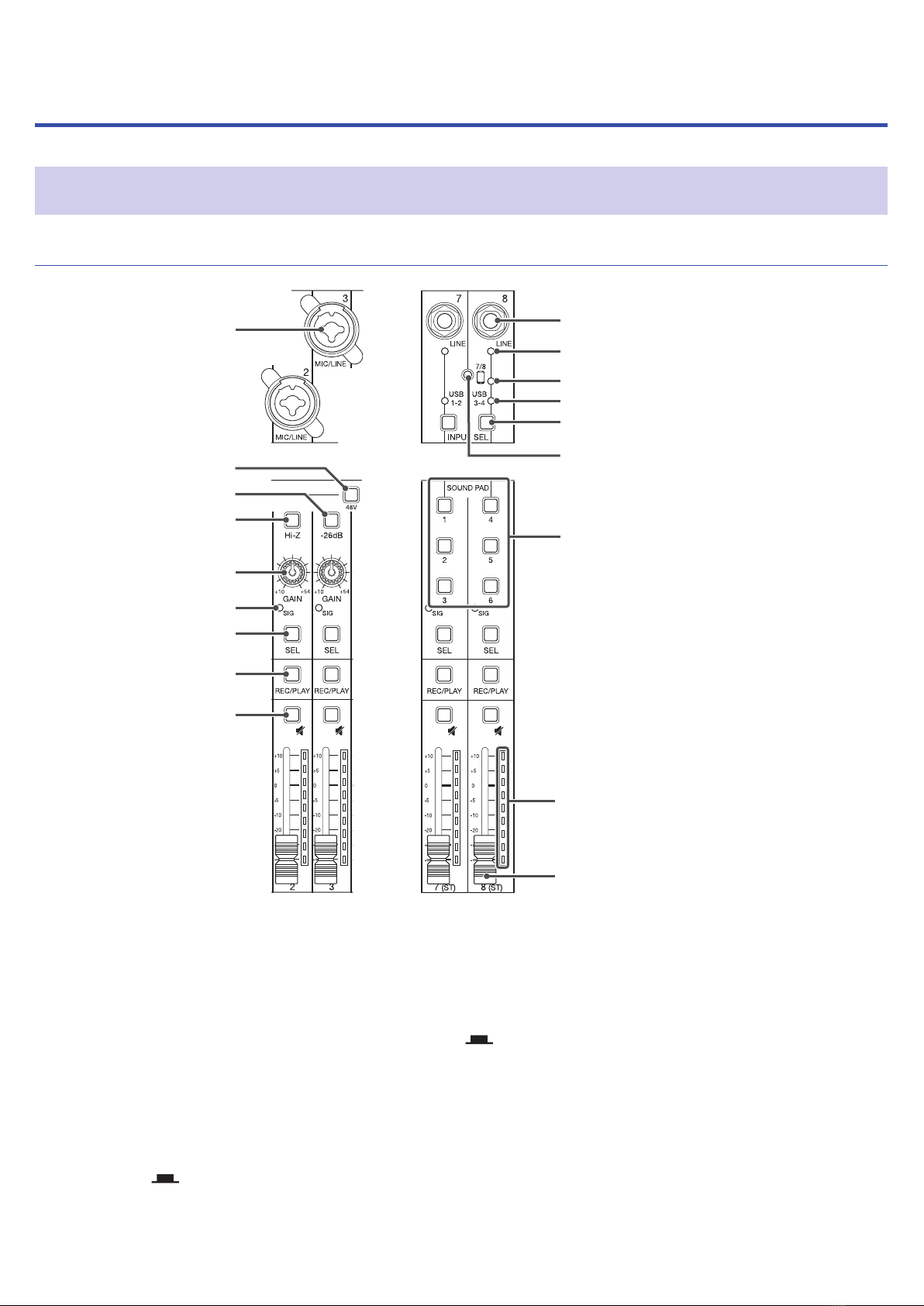
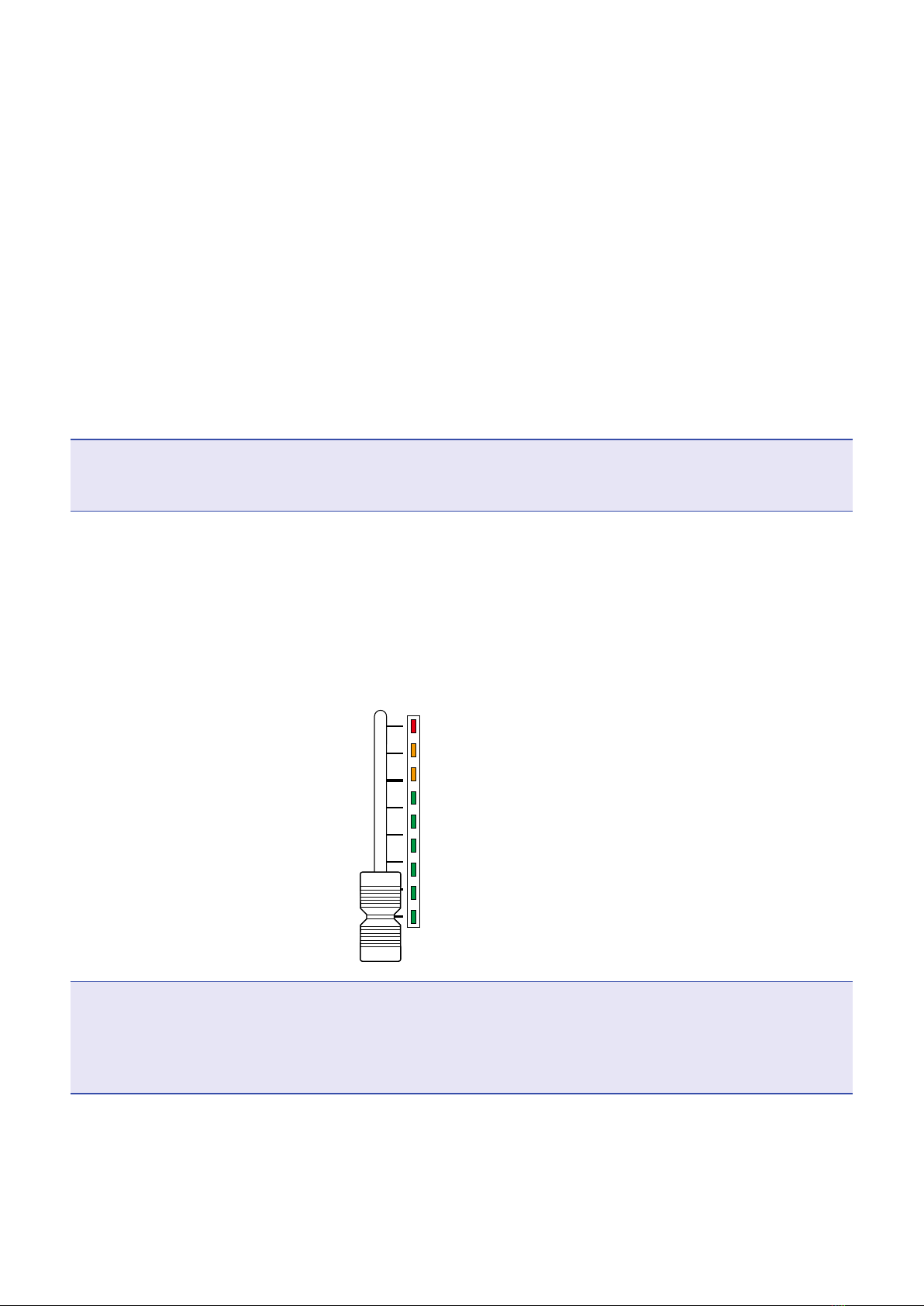
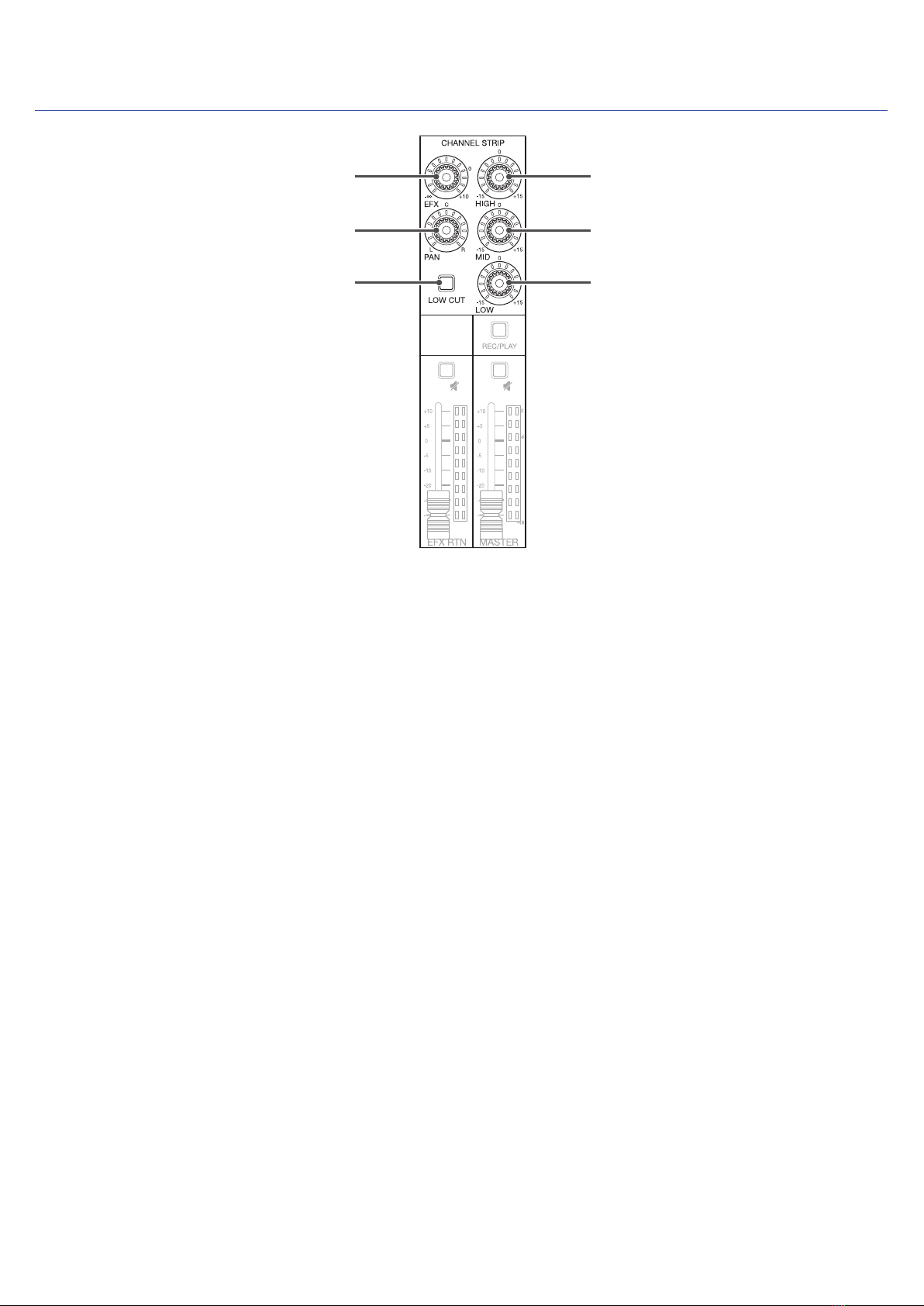
Names and functions of parts ������������ 5
Top ������������������������������� 5
Back ����������������������������� 19
Bottom ���������������������������� 20
Equipment connection examples ��������� 21
Podcasting ������������������������� 21
Live PA system ����������������������� 22
Preparations ��������������������� 23
Providing power ���������������������� 23
Turning the power on and off ������������ 25
Turning the power on ������������������� 25
Turning the power off ������������������ 26
Using the SETTING screen ������������� 27
Mixer �������������������������� 28
Outputting input sounds from output devices ��� 28
Adjusting the tone and panning ������������ 30
Using the built-in effects ���������������� 31
Using scene functions ������������������ 33
Setting signals output from MONITOR OUT A–C � 36
Connecting smartphones ���������������� 39
Recording and playback ��������������� 40
Preparing to record �������������������� 40
Recording/overdubbing and playing recordings �� 42
Adding marks ����������������������� 44
Redoing parts of recordings (punching in/out) �� 45
Mixing down tracks �������������������� 46
Starting recording automatically ����������� 48
Pre-recording before recording starts �������� 50
Selecting projects for playback ������������ 51
SOUND PAD functions ���������������� 52
Playing sounds with SOUND PAD buttons ����� 52
Assigning audio les to SOUND PAD buttons ��� 53
Changing SOUND PAD playback methods ����� 57
Changing SOUND PAD playback levels ������� 59
Metronome ���������������������� 61
Enabling the metronome ���������������� 61
Changing metronome settings ������������ 62
Projects ������������������������ 66
Changing project names ���������������� 66
Deleting projects ��������������������� 68
Protecting projects �������������������� 69
Checking project information ������������� 70
Checking, deleting and moving to marks ������ 71
Audio les ����������������������� 72
Deleting audio les �������������������� 72
Assigning audio les to tracks ������������� 74
Audio interface �������������������� 76
Installing the driver �������������������� 76
Connecting to a computer ��������������� 77
Connecting to an iOS device �������������� 79
Inputting return signals from the computer on
channels 7/8 ������������������������ 81
Card reader ���������������������� 82
SD card folder structure ����������������� 82
Using card reader functions �������������� 83
Recording and playback settings ��������� 85
Changing the recording format ������������ 85
Changing automatic recording settings ������� 86
Showing recording levels on level meters ������ 88
Compensating for latency during input and output 89
Changing the playback mode ������������� 90
SD card settings ������������������� 91
Checking the open space on SD cards �������� 91
Formatting SD cards ������������������� 92
Testing SD card performance ������������� 93
Making various settings ��������������� 96
Setting the date and time ���������������� 96
Changing the sampling rate �������������� 97
Disabling the automatic power saving function �� 98
Adjusting the display contrast ������������� 99
Setting the display backlight ��������������100
Setting the type of batteries used �����������101
Setting the battery saving mode ������������102
Restoring settings to factory defaults ��������103
Checking the rmware versions ������������104
Updating the rmware ������������������105
Troubleshooting �������������������107
Specications ���������������������110
Send effect specications �������������111
Mixer block diagram �����������������112
Contents
4

Names and functions of parts
Top
Input channel section
⑩ LINE input jack
⑫ Smartphone connection indicator
⑭ INPUT SEL button
① MIC/LINE input jack
② 48V switch
④ Hi-Z switch
③ −26dB switch
⑥ SIG indicator
⑤ GAIN knob
⑦ SEL button
⑧ REC/PLAY button
⑨ MUTE button
⑰ Level meter
⑱ Channel fader
⑪ LINE input indicator
⑬ USB indicator
⑮ Smartphone connection jack
⑯ SOUND PAD 1–6 buttons
①MIC/LINE input jack
These input jacks have built-in mic preamps. Connect mics, keyboards and guitars to them. These can be used
with both XLR and 1/4-inch (balanced or unbalanced) phone plugs.
②48V switch
This turns +48V phantom power on/off. Turn this on ( ) to supply phantom power to MIC/LINE input jacks
1–6.
③ −26dB switch
This attenuates (reduces) the input signal of the equipment connected to the MIC/LINE input jack (3–6) by 26
dB.
Turn this on ( ) when connecting line level equipment.
5

④Hi-Z switch
Use to switch the input impedance of the MIC/LINE input jack (1 or 2).
Turn it on ( ) when connecting a guitar or bass guitar.
⑤GAIN knob
Use to adjust the input gain of the mic preamp.
The range of adjustment depends on the on/off status of the MIC/LINE input jack switch (Hi-Z on channels
1–2 or −26dB on channels 3–6).
Jack Adjustment range
MIC/LINE input jack 1–2 (XLR) +10 – +54 dB
MIC/LINE input jack 1–2 (TRS) Hi-Z off +10 – +54 dB
Hi-Z on −3 – +41 dB
MIC/LINE input jack 3–6 −26dB off +10 – +54 dB
−26dB on −16 – +28 dB
⑥SIG indicator
This shows the signal level after adjustment by the GAIN knob.
The indicator color changes according to the signal level. Adjust so that it does not light red.
Lit red: Input signal level is close (−3 dBFS or higher) to the clipping level (0 dBFS)
Lit green: Input signal level is between −48 dBFS and −3 dBFS compared to the clipping level (0 dBFS)
⑦SEL button
Use to select a channel for parameter adjustment in the channel strip section.
Channels with lit SEL buttons are affected by channel strip section adjustments.
⑧REC/PLAY button
Use this button to switch between recording input signals to the SD card and playing back an already recorded
le from the SD card.
Status Explanation
Lit red Input signals will be recorded to the SD card after adjustment by the GAIN knob.
Lit green File playback signals will be input before the equalizer. In this state, signals
from input jacks are disabled.
Unlit Signals from input jacks are enabled.
⑨MUTE button
This mutes or unmutes signals.
To mute the signal, press this button to light it.
HINT
This has no effect on recording to the SD card.
⑩LINE input jack
Use this input jack to connect line level equipment. For example, connect a keyboard or audio device.
1/4-inch (unbalanced) phone plugs can be used with it.
NOTE
The LINE input jacks and the smartphone connection jack cannot be used at the same time.
6

⑪LINE input indicator
This lights when the LINE input is enabled.
⑫Smartphone connection indicator
This lights when the Smartphone connection jack is enabled.
⑬USB indicator
This lights when the input of audio return signals output from a computer is enabled.
⑭INPUT SEL button
Use to set the input signal for channel 7/8 to the input jack, the USB audio return, or the SOUND PAD function.
Press this button to switch the enabled input.
⑮Smartphone connection jack
Connect a smartphone or similar device here. By using a 4-contact mini-plug cable, the signal can be input from
a smartphone and the master mix signal can be sent back (without the channel 8 signal) to it simultaneously.
NOTE
The LINE input jacks and the smartphone connection jack cannot be used at the same time. When the smart-
phone connection jack is enabled as the channel 8 input, channel 7 LINE input is disabled.
⑯SOUND PAD 1–6 buttons
When the SOUND PAD function is enabled, the sounds assigned to each of them can be played.
PAD 1–3 sounds are input on channel 7 and PAD 4–6 sounds are input on channel 8.
⑰Level meter
This shows the signal level after adjustment by the channel fader.
Range shown: −48 dB – 0 dB
0 (clipping level)
-3
-6
-48
(dBFS)
-12
-18
-24
-30
-36
NOTE
• If the actual channel fader position differs from the channel fader position recalled using the scene function,
for example, the level meter will show the recalled fader position. To enable fader operation, move the fader to
the position shown by the level meter.
• The colors of the level meters cannot be shown properly on grayscale devices.
⑱Channel fader
This adjusts the channel signal level in a range from −∞ to +10 dB.
7

CHANNEL STRIP section
⑤ MID knob
⑥ LOW knob
④ HIGH knob
① EFX knob
② PAN knob
③ LOW CUT button
①EFX knob
The amount that can be sent to the EFX bus can be set from −∞ to +10 dB.
②PAN knob
This adjusts the position in the stereo output bus.
On channels 7 and 8, this adjusts the left and right volume balance.
③LOW CUT button
This turns on/off the high-pass lter, which cuts low frequencies. When ON, signals below 75 Hz are attenu-
ated 12 dB/octave.
④HIGH knob
This adjusts the boost/cut of high-frequency equalization.
Type: shelving
Gain range: −15 dB – +15 dB
Frequency: 10 kHz
⑤MID knob
This adjusts the boost/cut of mid-frequency equalization.
Type: peaking
Gain range: −15 dB – +15 dB
Frequency: 2.5 kHz
⑥LOW knob
This adjusts the boost/cut of low-frequency equalization.
Type: shelving
Gain range: −15 dB – +15 dB
Frequency: 100 Hz
8

Send effect (SEND EFX) section
① EXT RTN MUTE button
② EFX RTN level meters
③ EFX RTN fader
①EXT RTN MUTE button
This mutes or unmutes the signal sent from the built-in effect.
To mute the signal, press this button to light it.
②EFX RTN level meters
These show the levels of the signals sent from the built-in effect to the master bus after adjustment by the EFX
RTN fader. Their range is from −48 dB to 0 dB.
③EFX RTN fader
This adjusts the levels of the signals sent from the built-in effect to the master bus in a range from −∞ dB to
+10 dB.
NOTE
If the actual EFX RTN fader position differs from the EFX RTN fader position recalled using the scene function,
for example, the level meter will show the recalled fader position. To enable fader operation, move the fader to
the position shown by the level meter.
9

Output section
① MASTER OUT XLR jacks
④ MONITOR OUT PHONES A–C jacks
⑤ MONITOR OUT knobs A–C
⑦ MASTER REC/PLAY button
⑥ MONITOR OUT A–C switches
⑧ MASTER MUTE button
⑨ Master level meters
⑩ Master fader
② MASTER OUT PHONES jack
③ MASTER OUT PHONES knob
①MASTER OUT XLR jacks
These jacks output signals after volume adjustment by the master fader.
Connect them to a power amplier, a PA system or speakers with built-in ampliers, for example.
These support balanced output with XLR connectors (2 HOT).
②MASTER OUT PHONES jack
This headphone output jack outputs the same signals as the MASTER OUT jacks.
③MASTER OUT PHONES knob
Use to adjust the volume of signals output from the MASTER OUT PHONES jack.
④MONITOR OUT PHONES A–C jacks
These headphone output jacks output signals after volume adjustment by the MONITOR OUT A–C knobs.
NOTE
The MONITOR OUT PHONES A–C jacks can be set to output the same signals as the MASTER OUT jacks or the
signals set separately in MIXER mode. ( →“Setting signals output from MONITOR OUT A–C” on page 36)
10

⑤MONITOR OUT knobs A–C
Use to adjust the volumes of the signals output from the MONITOR OUT PHONES A–C jacks.
⑥MONITOR OUT A–C switches
These switch the signals output from the MONITOR OUT PHONES A–C jacks.
Status Explanation
MASTER The same signals as those output from the MASTER OUT jacks are output.
MIX A–C Signals set in MIXER mode are output.
⑦MASTER REC/PLAY button
Use this button to switch between recording the signal input on the master bus to the SD card and playing back
an already recorded le from the SD card.
Status Explanation
Lit red The signal will be recorded to the SD card after adjustment by the master fader.
Lit green The playback signal of a le is inserted on the master bus. The REC/PLAY buttons of
other channels will become unlit at this time.
Unlit Files will neither be recorded nor played back.
⑧MASTER MUTE button
This mutes or unmutes the MASTER OUT jacks. To mute the signal, press this button to light it.
⑨Master level meters
These show the signal levels output from the MASTER OUT jacks in a range from −48 dB to 0 dB.
⑩Master fader
This adjusts the signal levels output from the MASTER OUT jacks in a range from −∞ to +10 dB.
NOTE
If the actual master fader position differs from the master fader position recalled using the scene function, for
example, the level meter will show the recalled fader position. To enable fader operation, move the fader to the
position shown by the level meter.
When AUTO REC is activated, however, the master fader position will not be shown.
11

Display, function and mode section
① Display
② Selection encoder
③ Function buttons
④ MIXER mode button
⑤ SCENE mode button
⑥ EFFECT mode button
⑦ RECORDER mode button
①Display
This shows the status of the selected mode and other information. ( →“Function buttons and display appear-
ance in each mode” on page 13)
②Selection encoder
Use this to change menus and values and to move between items.
③Function buttons
The functions change according to the selected mode. ( →“Function buttons and display appearance in each
mode” on page 13)
④MIXER mode button
This enables the MIXER mode functions of the function buttons and opens the MIXER screen on the display.
In MIXER mode, the layers used for mixing can be checked and changed. In addition, mixes can be copied and
audio interface and SOUND PAD settings can be changed.
Press this when making settings to return to the MIXER screen.
⑤SCENE mode button
This enables the SCENE mode functions of the function buttons and opens the SCENE screen on the display.
In SCENE mode, scenes can be changed and saved and the mixer can be reset.
⑥EFFECT mode button
This enables the EFFECT mode functions of the function buttons and opens the EFFECT screen on the display.
In EFFECT mode, effects can be selected, checked and adjusted.
⑦RECORDER mode button
This enables the RECORDER mode functions of the function buttons and opens the RECORDER screen on the
display. In RECORDER mode, recorder operations are enabled. In addition, the SETTING screen where various
settings are made can be opened.
Press this when making settings to return to the RECORDER screen.
12

Function buttons and display appearance in each mode
█MIXER mode
① MASTER and MIX A–C buttons
⑤ SOUND PAD settings button
④ AUDIO I/F button
③ MIX PASTE button
② MIX COPY button
①MASTER and MIX A–C buttons
The signal balance set using the channel faders can be switched as layers according to the outputs you want
to show and adjust.
• MASTER button: Show and adjust the settings used for MASTER OUT output.
• MIX A–C buttons: Show and adjust the settings used for MONITOR OUT A–C outputs.
NOTE
• The following parameters can have separate settings for the MASTER and MONITOR OUT A–C.
– Fader positions (each channel)
– Fader positions (EFX RETURN)
• The following parameters are shared by the MASTER and the MONITOR OUT A–C mixes.
MUTE ON/OFF, LOW CUT ON/OFF, EQ HIGH, EQ MID, EQ LOW, SEND EFX, PAN, SEND EFX TYPE, SEND EFX
parameters 1 and 2
②MIX COPY button
This copies fader position information for the currently selected mix.
③MIX PASTE button
This applies the copied fader position information to the currently selected mix.
④AUDIO I/F button
This opens a screen where audio interface function settings can be changed.
⑤SOUND PAD settings button
This opens a screen where SOUND PAD settings can be changed.
13

①
②
No. Item Explanation
①Selected mix This highlights the selected mix.
②Remaining battery charge
(when battery-powered)
This shows the remaining battery charge. When the remaining battery charge
becomes low, replace the batteries or connect an AC adapter.
14

█EFFECT mode
① Effect type buttons
①Effect type buttons
The currently selected effect type appears lit.
Press a button to change the effect. The selected effect will be shown on the display. Its parameters can be
changed using the Selection encoder.
(→“Send effect specications” on page 111)
⑤
①
②
③
④
No. Item Explanation
①Effect type This shows the selected effect type.
②Parameter This shows the name of an adjustable effect parameter.
③Parameter knob This shows a parameter knob.
The knob position shows the parameter setting value.
④Parameter setting value This shows the parameter setting value.
It appears highlighted when selected.
⑤Remaining battery charge
(when battery-powered)
This shows the remaining battery charge. When the remaining battery charge
becomes low, replace the batteries or connect an AC adapter.
15

█SCENE mode
② RESET button
① 1–7 buttons
①1–7 buttons
Use these buttons to select the scene used to save the current mixer settings and to recall saved scenes.
Press these buttons to open screens where SAVE, RECALL and CANCEL can be selected.
②RESET button
Press this button to reset the current mixer settings to the factory defaults.
Press this button to open a screen where RECALL and CANCEL can be selected.
③
①
②
No. Item Explanation
①Scene number This shows the number of the selected scene.
“NOT SELECTED” will appear when none is selected.
②EDITED status This appears if the selected scene has been changed.
③Remaining battery charge
(when battery-powered)
This shows the remaining battery charge. When the remaining battery charge
becomes low, replace the batteries or connect an AC adapter.
16

█RECORDER mode
④ SETTING button
⑧ OVERDUB button
⑦ REC button
⑥ PLAY button
⑤ STOP button
① REW button
③ TEMPO button
② FF button
①REW button
Press to move to the previous mark.
Press when at the beginning to move to the previous project. Press and hold to search backward. (The longer
pressed, the faster the speed becomes.)
②FF button
Press to move to the next mark.
If it is the last mark, this moves to the next project. Press and hold to search forward. (The longer pressed, the
faster the speed becomes.)
③TEMPO button
This sets the tempo of the metronome built into the recorder.
The tempo will be detected from the average value when this button is pressed repeatedly.
When the METRONOME setting is enabled, during recording and playback and when the Delay effect, which
synchronizes with tempo, is selected, the button blinks at a tempo of 40.0–250.0 bpm.
④SETTING button
Press to open the SETTING screen.
⑤STOP button
This stops the recorder.
⑥PLAY button
Press to start recorder playback.
• During playback, it lights green.
• When playback is paused, it blinks green.
17

⑦REC button
This puts the recorder in recording standby.
• During recording, it lights red.
• When recording is paused, it blinks red.
⑧OVERDUB button
This sets whether recording is overdubbed in the current project or whether a new project is created and new
recording conducted. When on, this button lights and overdubbing occurs in the current project.
⑤
②
③
④
①
⑥
⑦
⑧
⑨
No. Item Explanation
①Project name
This shows the project name.
"<" appears if there is another project before this one in the folder.
">" appears if there is another project after this one in the folder.
②Status icon
This shows the status as follows.
: Stopped
: Paused
: Recording
: Playing back
③Mark
This shows the mark number and the status as follows.
: At mark (A mark has been added at the counter location.)
: Not at mark (No mark has been added at the counter location.)
④Progress bar The progress bar shows the amount of time from the beginning to the end of the
project.
⑤Remaining battery charge
(when battery-powered)
This shows the remaining battery charge. When the remaining battery charge
becomes low, replace the batteries or connect an AC adapter.
⑥Counter This shows the time in hours, minutes and seconds.
⑦Longest le time in project This shows the length of the longest le in the project.
⑧Remaining recordable time
This shows the remaining recordable time.
This will change automatically according to the number of channels that have
recording enabled with .
⑨SD card icon This is shown when an SD card is detected.
18

Back
① POWER switch
② SD card slot
①POWER switch
This turns the power on and off.
Switch to ON to turn the power on. Switch to OFF to turn the power off.
When the POWER switch setting is changed to OFF, the current mixer settings are automatically saved in the
and in the settings le in the project folder on the SD card.
②SD card slot
This slot is for SD cards.
The supports cards that conform to SDHC and SDXC specications.
HINT
SD cards can be can tested for usability with the . ( →“Testing SD card performance” on page 93)
19

Bottom
① Micro USB port
② Battery compartment cover
①Micro USB port
This Micro USB 2.0 port can be used to connect an AC adapter or computer.
A mobile battery, for example, can also be connected to run on bus power.
②Battery compartment cover
Remove when installing or removing batteries.
The can run on 4 AA batteries.
20
Table of contents
Other Zoom Music Mixer manuals