Zoom LiveTrak L-20R User manual

© 2019 ZOOM CORPORATION
Copying or reprinting this manual in part or in whole without permission is prohibited.
Product names, registered trademarks and company names in this document are the property of their respective companies. All trademarks and regis-
tered trademarks in this document are for identification purposes only and are not intended to infringe on the copyrights of their respective owners.
Proper display is not possible on grayscale devices.
You must read the Usage and Safety Precautions before use.
Operation Manual

Operation Manual overview
You might need this manual in the future. Always keep it in a place where you can access it easily.
The contents of this document and the specifications of the product could be changed without notice.
• Windows®is a trademark or registered trademark of Microsoft®Corporation.
• Macintosh, macOS and iPad are trademarks or registered trademarks of Apple Inc.
• iOS is a trademark or registered trademark of Cisco Systems, Inc. and used under license.
• App Store is a service mark of Apple Inc.
• The SD, SDHC and SDXC logos are trademarks.
•The Bluetooth®word mark and logo are registered trademarks of Bluetooth SIG, Inc. and these marks
are used under license by Zoom Corporation. Other trademarks and trade names are the property of their
respective companies.
• Other product names, registered trademarks and company names in this document are the property of
their respective companies.
Note: All trademarks and registered trademarks in this document are for identification purposes only and
are not intended to infringe on the copyrights of their respective owners.
Recording from copyrighted sources, including CDs, records, tapes, live performances, video works and
broadcasts, without permission of the copyright holder for any purpose other than personal use is prohibit-
ed by law. Zoom Corporation will not assume any responsibility related to infringements of copyrights.
1

Introduction
Thank you very much for purchasing a ZOOM LiveTrak .
The fuses the features of a digital mixer, a multitrack recorder and a USB audio interface to pro-
vide a powerful tool for both live performance and studio production. The smart and compact is
designed especially to be controlled from an iOS device and a single unit can simultaneously mix, moni-
tor and record live performances.
Main features of the
Remote control using iOS devices
Set up the in the best location for connecting with other equipment and then use the L-20 Control
iOS app to mix wirelessly while listening from anywhere in the venue, including from audience seats and
in front of monitor speakers.
20-channel digital mixer & multitrack recorder
The combines a digital mixer with 20 total input channels (16 mono and 2 stereo), a multitrack
recorder that can simultaneously record up to 22 tracks, and a 22-in/4-out USB audio interface. Compact
and lightweight, this digital mixer is easy to transport and can even be used with PA systems for live per-
formances in rehearsal studios, cafés and other small venues.
High-quality mic preamps
The has high-quality mic preamps built-in for 16 channels. The high-quality analog inputs, which
can provide +48 V phantom power, have a −128 dBu EIN rating and +60 dB maximum input gain. In addi-
tion, channels 1 and 2 also support Hi-Z input, while channels 3 to 16 have PAD functions (26 dB attenua-
tion), enabling them to accept high levels of input.
6 monitor output channels
In addition to the MASTER OUT, the also has 6 MONITOR OUT channels. The MONITOR OUT
mixes can be set separately for each output, enabling different mixes to be sent to individual performers.
Moreover, they support output to both headphones and monitor speakers.
Recorder can simultaneously record 22 tracks and play 20 tracks
The can simultaneously record every channel and the master fader stereo signal output for a total
of 22 tracks. Since the recorded data is saved in 16/24-bit, 44.1/48/96 kHz WAV format, the files can easily
be copied to a computer and used in a DAW. In addition, overdubbing and punching in/out can be done as
expected with a multitrack recorder.
22-in/4-out USB audio interface
The can be used as a 22-in/4-out USB audio interface.The signals from each input and the master
fader output can be recorded in a DAW. In addition, signals output from a computer can also be assigned
to a stereo channel. Class compliant mode, which enables connection with iOS devices, is also supported.
2

Operation Manual overview ������� 1
Introduction ��������������� 2
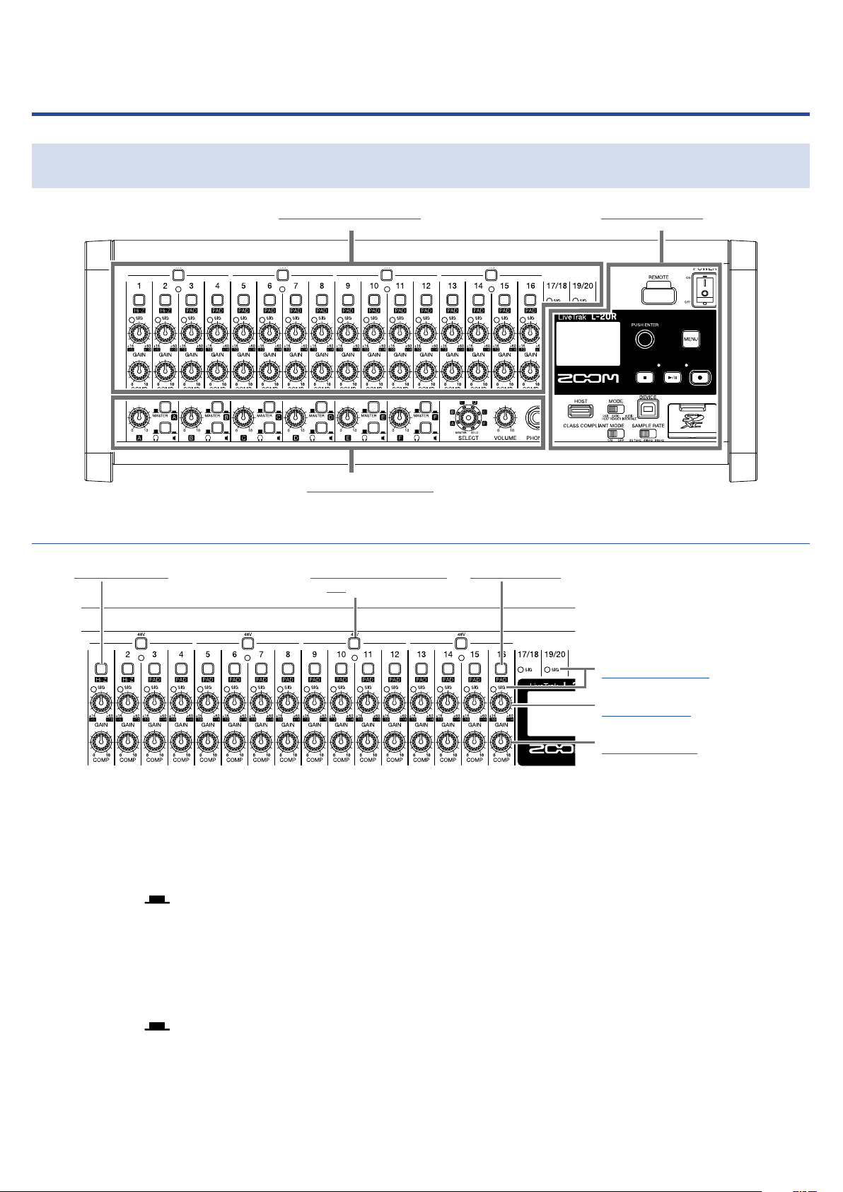
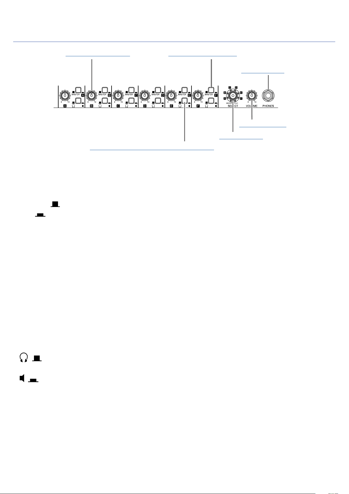
Names and functions of parts �������� 5
Front ������������������ 5
Back ������������������ 10
Equipment connection examples ������ 12
Live PA system ������������� 12
Display overview ������������� 13
Home Screen �������������� 13
Installing L-20 Control ����������� 14
L-20 Control operation screen ������� 15
Main sections of screen ��������� 15
Input channel section ���������� 16
Master section ������������� 19
Toolbar (access to all screens) ������ 25
Turning the power on and off ������� 30
Turning the power on ���������� 30
Turning the power off ���������� 32
Pairing (connecting) with the ���� 33
Using the MENU screen ���������� 35
Mixer ������������������� 36
Outputting input sounds from output devices
�������������������� 36
Adjusting the tone and panning ����� 39
Changing channel colors �������� 41
Changing channel names �������� 42
Resetting channels ����������� 43
Using the built-in effects �������� 44
Using scene functions ��������� 46
Setting signals output from MONITOR OUT A–F
�������������������� 49
Graphic equalizer (G-EQ) �������� 53
Recording and playback ���������� 54
Preparing to record ����������� 54
Recording/overdubbing and playing recordings
�������������������� 56
Adding marks ������������� 59
Redoing parts of recordings (punching in/out)
�������������������� 61
Mixing down tracks ����������� 63
Starting recording automatically ����� 65
Pre-recording before recording starts �� 67
Selecting the folder where projects are saved
�������������������� 68
Selecting projects for playback ������ 69
Using the metronome ����������� 70
Enabling the metronome �������� 70
Changing metronome settings ������ 71
Projects ����������������� 76
Changing project names �������� 76
Deleting projects ������������ 78
Protecting projects ����������� 79
Checking project information ������ 80
Saving projects to USB flash drives ��� 81
Importing projects from USB flash drives � 83
Checking, deleting and moving to marks � 85
Audio files ���������������� 86
Deleting audio files ����������� 86
Exporting audio files to USB flash drives � 88
Importing audio files from USB flash drives 90
Using audio interface functions ������ 92
Installing the driver ����������� 92
Connecting to a computer �������� 93
Inputting return signals from the computer to a
stereo channel ������������� 94
Using card reader functions �������� 95
Recording and playback settings ������ 96
Changing the recording format ����� 96
Changing automatic recording settings �� 97
Compensating for latency that occurs during in-
put and output ������������� 99
Changing the playback mode ������ 100
Changing the input signal recording source 100
SD card settings ������������� 101
Checking the open space on SD cards �� 101
Formatting SD cards ���������� 101
Testing SD card performance ������ 102
Making various settings ���������� 105
Setting the date and time �������� 105
Setting the footswitch ���������� 106
Changing the sampling rate ������� 107
Disabling the automatic power saving function
�������������������� 108
Contents
3

Adjusting the display contrast ������ 108
Restoring settings to factory defaults ���� 109
Checking the versions ����������� 110
Checking the firmware versions � 110
Checking the L-20 Control version ���� 111
Updating the firmware ���������� 112
Troubleshooting �������������� 113
Specifications ��������������� 116
Send effect specifications ��������� 117
Mixer block diagram ������������ 118
4

Names and functions of parts
Front
Input channel section Display section
Monitoring section
Input channel section
1Hi-Z switch 248V switch/indica-
tor
3PAD switch
4SIG indicator
5GAIN knob
6COMP knob
1Hi-Z switch
Use to switch the input impedance of MIC/LINE input jack 1 (or 2).
248V switch/indicator
This turns +48V phantom power on/off.
Turn this on ( ) to supply phantom power to MIC/LINE input jacks 1–4, 5–8, 9–12 or 13–16.
The indicator lights when the switch is on.
3PAD switch
This attenuates (reduces) the input signal of the equipment connected to MIC/LINE input jacks 3–16 by
26 dB.
Turn this on ( ) when connecting line level equipment.
4SIG indicator
This shows the signal level after adjustment by the GAIN knob.
The indicator color changes according to the signal level. Adjust so that it does not light red.
5

Lit red: input signal level is close (−3 dBFS or higher) to the clipping level (0 dBFS)
Lit green: input signal level is between −48 and −3 dBFS compared to the clipping level (0 dBFS)
5GAIN knob
Use to adjust the input gain of the mic preamp.
The range of adjustment depends on the on/off status of the MIC/LINE input jack switch (Hi-Z on chan-
nels 1–2 or PAD on channels 3–16).
Jack Adjustment range
MIC/LINE input jack 1–2 (XLR) +16 – +60 dB
MIC/LINE input jack 1–2 (TRS) Hi-Z off +16 – +60 dB
Hi-Z on (TS) +6 – +50 dB
MIC/LINE input jack 3–16 PAD off +16 – +60 dB
PAD on -10 – +34 dB
6COMP knob
Use to adjust the amount of compression.
6

Monitoring section
1MONITOR OUT knob
3PHONES jack
4VOLUME knob
5SELECT knob
6MONITOR OUT PHONES/SPEAKER switch
2MONITOR OUT switch
1MONITOR OUT knob
Use to adjust the volume of the signals output from the MONITOR OUT jacks.
2MONITOR OUT switch
This switches the signal output from the MONITOR OUT jacks.
MASTER ( ):The signal after adjustment by the master fader is output.
A–F ( ):The signal set by the fader mode is output.
3PHONES jack
Connect headphones here.
4VOLUME knob
Use this to adjust the volume of the PHONES jack.
5SELECT knob
Use this to select the signal output from the PHONES jack.
The options are MASTER, SOLO and MONITOR OUT A–F.
MASTER:The signal after adjustment by the master fader is output.
A–F:The signal set by the fader mode is output.
SOLO:The signals of soloed channels are output.
6MONITOR OUT PHONES/SPEAKER switch
Use this to select the type of equipment connected to the MONITOR OUT jack.
( ): Select this when headphones are connected. The signal output from the MONITOR OUT jack
will be stereo.
( ): Select this when speakers are connected.The signal output from the MONITOR OUT jack will be
balanced mono.
7

Display section
1REMOTE jack
"Display
#MODE switch
$USB HOST port
%CLASS COMPLIANT
MODE switch
2POWER switch
3Selection encoder
4MENU button
5PLAY/PAUSE button/indicator
6REC button/indicator
7STOP button
8SD card slot
9USB DEVICE port
!SAMPLE RATE switch
1REMOTE jack
A ZOOM wireless adapter (e.g. BTA-1), can be connected here.
2POWER switch
This turns the unit on and off.
Switch to | to turn the power on. Switch to to turn the power off.
When the POWER switch setting is changed to OFF, the current mixer settings are automatically saved
in the unit and in the settings file in the project folder on the SD card.
3Selection encoder
Use this to change menus and values and to move between items.
Operation Result
Turn when Home Screen
open Search forward or backward in one-second increments.
Press when Home Screen
open Set a mark.
Turn when menu open Move between parameters and change values.
Press when menu open Confirm parameter value.
4MENU button
This opens the menu.
5PLAY/PAUSE button/indicator
This starts and pauses recorder playback, and the indicator shows the playback status.
Status Explanation
Lit green The recorder is playing back.
Blinking green Playback is paused.
8

6REC button/indicator
This puts the recorder into standby, and the indicator shows the recording status.
Status Explanation
Lit red The recorder is recording or in recording standby.
Blinking red Recording is paused.
7STOP button
This stops the recorder.
8SD card slot
This slot is for SD cards.
The supports SD, SDHC and SDXC card specifications.
HINT
SD cards can be can tested for usability with the . (→"Testing SD card performance" on page
102)
9USB DEVICE port
This USB 2.0 port is for connecting with a computer.
It will start up as a card reader or audio interface, depending on the MODE switch selection.
Card reader mode
Operating as an SD card reader, data can be exchanged with a computer.
Audio interface mode
Operating as an audio interface, audio data can be exchanged with a computer.
Inputs: The signals from channels 1–20 after they pass through their compressors and the master fader
output signals are input to the computer.
!SAMPLE RATE switch
Set the sampling rate used by the unit.
This cannot be changed after starting up.
"Display
This shows the recorder status and MENU screen.
#MODE switch
Set whether to use as a USB HOST, card reader or audio interface.This cannot be changed after starting
up.
$USB HOST port
This USB 2.0 HOST port is for connecting USB flash drives.
Projects and audio files can be saved on and loaded from connected USB flash drives.
%CLASS COMPLIANT MODE switch
Use this to turn Class Compliant Mode ON/OFF.This cannot be changed after starting up.
Set it to ON when connected to an iOS device.
9

Back
1CONTROL IN connector
5MIC/LINE input jacks
7DC IN 12V AC adapter connector 6LINE input jacks (RCA)
2MONITOR
OUT jacks
3MASTER
OUT jacks
4LINE input
jacks (TS)
1CONTROL IN connector
A footswitch (ZOOM FS01) can be connected here.
The footswitch can be assigned to one function: starting/stopping recorder playback, manually punch-
ing in/out or muting/unmuting the built-in effect. (→"Setting the footswitch" on page 106)
2MONITOR OUT jacks
These jacks output signals after volume adjustment by the MONITOR OUT knob.
Connect monitor speakers or headphones for performers here.
These support balanced 1/4-inch phone output.
NOTE
• The MONITOR OUT jacks can be set to output the same signals as the MASTER OUT jacks or signals
set separately by the fader mode. (→"Setting signals output from MONITOR OUT A–F" on page 49)
• Set the MONITOR OUT PHONES/SPEAKER switches according to the type of connected equipment.
3MASTER OUT jacks
These jacks output signals after volume adjustment by the master fader.
Connect them to a power amplifier, a PA system or speakers with built-in amplifiers, for example.
These support balanced output with XLR connectors (2 HOT).
4LINE input jacks (TS)
Use these input jacks to connect line level equipment.
For example, connect keyboards or audio devices. These can be used with 1/4-inch (unbalanced) phone
plugs.
NOTE
If only the left LINE input jack (TS) channel is connected, it will be handled as a mono channel.
10

5MIC/LINE input jacks
These input jacks have built-in mic preamps.
Connect mics, keyboards and guitars to them. These can be used with both XLR and 1/4-inch (balanced
or unbalanced) phone plugs.
6LINE input jacks (RCA)
Use these input jacks to connect line level equipment.
For example, connect audio devices.These can be used with RCA pin connectors.
NOTE
If both the RCA andTS LINE input jacks are connected, theTS input jacks will be used.
7DC IN 12V AC adapter connector
Connect the included AC adapter here.
11

Equipment connection examples
Live PA system
Front
Operator
headphones
ZOOM
wireless adapter
(e.g. BTA-1) iPad
Computer
(for recording and playback)
Back
DI
Performer
headphones/speakers × 6
Keyboard
Drums
Drum mic
Electric
guitar
Vocal/chorus
mic
Electric acoustic
guitar
Bass
Portable
audio player
Powered speakers
(main)
Footswitch
12

Display overview
Home Screen
①
⑨ ⑩
⑤⑥ ⑧⑦
⑫
⑬
⑭
④
②
③
⑪
No. Item Explanation
1Project name
This shows the project name.
"<" appears if there is another project before this one in the folder.
">" appears if there is another project after this one in the folder.
2Status icon
This shows the status as follows.
: Stopped
: Paused
: Recording
: Playing back
3Counter This shows the hour: minute: second.
4Progress bar The progress bar shows the amount of time from the beginning to the end of
the project.
5Folder name The folder where the project is saved will be shown as FOLDER01 – FOLD-
ER10.
6PLAY MODE icon This shows the PLAY MODE setting. (→"Changing the playback mode" on
page 100)
7Metronome icon This is shown when the metronome is enabled. (→"Enabling the metronome"
on page 70)
8Project protection icon This is shown when project protection is enabled. (→"Protecting projects" on
page 79)
9Remaining recordable time
This shows the remaining recordable time.
This will change automatically according to the number of channels that are
in recording standby.
!Recording file format This shows the recording file format used by the recorder.
"Current date and time This shows the current date and time.
#SD card icon This is shown when an SD card is detected.
$Mark
This shows the mark number and the status as follows.
: at mark (mark added at counter location)
: not at mark (mark not added at counter location)
%Longest file time in project This shows the length of the longest file in the project.
13

Installing L-20 Control
Install the dedicated L-20 Control app on an iPad.
This app can be used to operate the .
1. Use the iPad to scan the following 2D code and install L-20 Control from the App Store.
HINT
If the 2D code cannot be scanned, open the App Store and search for “L-20 Control”.
NOTE
• When you launch L-20 Control, you must pair it with the that it will operate.(→"Pairing (con-
necting) with the " on page 33)
• A Zoom wireless adapter (e.g. BTA-1) must be installed in the to remotely control it from an
iPad. With L-20 Control, transmission up to 10 m is possible when used indoors without obstacles.
14

L-20 Control operation screen
Main sections of screen
1Input channels
4Meter bridge
2Toolbar 3Master section
1Input channels
This section shows the settings of the input channels and effects. On this screen, the pan, fader and ef-
fect parameters for each channel can be adjusted precisely.The REC/PLAY, MUTE and SOLO settings can
also be changed.
2Toolbar
Tap buttons on the toolbar to access screens including the device list, settings, channel strip, effect,
graphic equalizer and recorder panel screens.
3Master section
The master section shows settings, including for the master fader, the scene, the fader mode and mon-
itor output. On this screen, the master fader and monitor output parameters can be adjusted precisely.
Scene and fader mode settings can also be changed.
4Meter bridge
For each channel, the meter bridge shows the pre-fader level or the selected FADER MODE post-fader
level.The pre/post setting can be changed on the Settings Screen.
15

Input channel section
1Phase indicator
2Input signal
3EQ display
4EFX 1/2 send
faders
$Effect type
name
5Pan fader
%Effect
parameter 1
6REC/PLAY
button
%Effect
parameter 2
&Effect return
fader
7MUTE button
8SOLO button
9Fader level
!Channel fader
"Level meter
#Channel name
1Phase indicator
Tapping the PHASE button in the channel strip will light this indicator.
2Input signal
This indicator shows the signal level after adjustment by the GAIN knob.
The indicator color changes according to the signal level. Adjust so that it does not light red.
Lit red: input signal level is close (−3 dBFS or higher) to the clipping level (0 dBFS)
Lit green: input signal level is between −48 and −3 dBFS compared to the clipping level (0 dBFS)
3EQ display
This shows the equalizer curve for the channel.
This to open the channel strip (→"Channel strip" on page 26).
4EFX 1/2 send faders
The amount that can be sent to the SEND EFX 1 and 2 buses can be set from −∞ to +10 dB.
5Pan fader
This adjusts the position in the stereo output bus.
On a stereo input channel, this adjusts the volume balance between the left and right channels.
NOTE
Double-tap a pan fader to reset it to its default value.
6REC/PLAY button
Use this button to switch between recording input signals to the SD card and playing back an already
16

recorded file from the SD card.
Status Explanation
Lit red Input signals will be recorded to the SD card.
Lit green
An already recorded file will be played back. Playback signals are input
before the equalizer. In this state, only files are played back. Signals
from input jacks are disabled.
Unlit Files will neither be recorded nor played back.
NOTE
Recorded signals can be set to either before or after the compressor. (→"Changing the input signal re-
cording source" on page 100)
7MUTE button
This mutes or unmutes the signal.
To mute the signal, tap this button to light it.
HINT
This has no effect on recording to the SD card.
8SOLO button
When a SOLO button is ON, the pre-fader signal can be heard from the PHONES jack.
At such times, the SELECT knob will automatically select SOLO.
9Fader level
This adjusts the channel signal level in a range from −∞ to +10 dB.
!Channel fader
This adjusts the channel signal level in a range from −∞ to +10 dB.
NOTE
To make precise adjustments, tap the fader cap, slide your finger right or left and then up and down.
"Level meter
This shows the signal level after adjustment by the channel fader.
Range shown: −48 dB – 0 dB
0 (Clipping level)
-3
-6
-9
-12
-15
-18
-21
-24
-27
-30
-48 (dBFS)
#Channel name
This shows the set channel name. (→"Channel strip" on page 26)
$Effect type name
17

This shows the name of the selected effect type.
%Effect parameters 1 and 2
Use these to adjust the parameters of the selected effect.
See "Send effect specifications" on page 117 for the parameters of each effect.
&Effect return fader
This adjusts the levels of the signals sent from the built-in effect to the master bus in a range from
−∞ dB to +10 dB.
HINT
To show the effect operation section for the input channels, swipe to reveal the right edge of the screen.
18

Master section
1Project name
2CHANGE PANEL
button
3Project counter
4FADER MODE
buttons
#REC button
5SCENE ON/OFF
button
$MONITOR OUT knob
61–9 buttons
%MASTER REC/PLAY button
&MUTE button
(SOLO CLEAR button
)Master fader level
~Master fader
+Master level meters
7SCENE RESET
8SCENE SAVE
9SCENE RECALL
!STOP button
"PLAY button
1Project name
This shows the name of the project.
2CHANGE PANEL button
Tap this to open the recorder panel.
3Project counter
This shows the hour: minute: second.
4FADER MODE buttons
These switch the mixes output from the MASTER OUT and MONITOR OUT A–F jacks.
M button: Use to show and adjust the mix output from the MASTER OUT jacks.
A–F buttons: Use to show and adjust the mixes output from the MONITOR OUT A–F jacks.
NOTE
The following parameters can have separate settings for the MASTER and A–F mixes.
• Fader positions (each channel)
• EFX1/2 RTN positions
5SCENE ON/OFF button
Tap this button, lighting it, to use the scene function.
61–9 buttons
Use these buttons to select the scene to use to save the current mixer settings and to load saved
scenes.
19
Other manuals for LiveTrak L-20R
1
Table of contents
Other Zoom Music Mixer manuals