Zoom LiveTrak L-20 User manual

© 2018 ZOOM CORPORATION
Copying or reprinting this manual in part or in whole without permission is prohibited.
Product names, registered trademarks and company names in this document are the property of their respective companies. All trademarks and regis-
tered trademarks in this document are for identification purposes only and are not intended to infringe on the copyrights of their respective owners.
You must read the Usage and Safety Precautions before use.
Operation Manual

■Operation Manual overview
You might need this manual in the future. Always keep it in a place where you can access it easily.
The contents of this document and the specications of the product could be changed without notice.
• Windows®is a trademark or registered trademark of Microsoft®Corporation.
• Macintosh, macOS and iPad are trademarks or registered trademarks of Apple Inc.
• The SD, SDHC and SDXC logos are trademarks.
• The Bluetooth®word mark and logo are registered trademarks of Bluetooth SIG, Inc. and these marks
are used under license by Zoom Corporation. Other trademarks and trade names are the property of
their respective companies.
• Other product names, registered trademarks and company names in this document are the property of
their respective companies.
Note: All trademarks and registered trademarks in this document are for identication purposes only and
are not intended to infringe on the copyrights of their respective owners.
Recording from copyrighted sources, including CDs, records, tapes, live performances, video works and
broadcasts, without permission of the copyright holder for any purpose other than personal use is prohibit-
ed by law. Zoom Corporation will not assume any responsibility related to infringements of copyrights.
1

Introduction
Thank you very much for purchasing a ZOOM LiveTrak (hereafter, " ").The has the fol-
lowing features.
20-channel digital mixer & multitrack recorder
The combines a digital mixer with 20 total input channels (16 mono and 2 stereo), a multitrack re-
corder that can simultaneously record up to 22 tracks, and a 22-in/4-out USB audio interface. Compact
and lightweight, this digital mixer is easy to transport and can even be used with PA systems for live per-
formances in rehearsal studios, cafés and other small venues.
High-quality mic preamps
The has high-quality mic preamps built-in for 16 channels. The high-quality analog inputs, which
can provide +48V phantom power, have a −128dBu EIN rating and +60dB maximum input gain. In addi-
tion, channels 1 and 2 also support Hi-Z input, while channels 3 to 16 have PAD functions (26dB attenua-
tion), enabling them to accept high levels of input.
6 MONITOR OUT channels
In addition to the MASTER OUT, the also has 6 MONITOR OUT channels.The MONITOR OUT mixes
can be set separately for each output, enabling different mixes to be sent to individual performers. More-
over, they support output to both headphones and monitor speakers.
Digital mixer that can be operated intuitively
Opening menus is not necessary with the . Every mixer parameter can be controlled with knobs
and keys just like an analog mixer. Each channel has a 3-band EQ, and the mono channels have compres-
sor functions. The mixer also includes high-quality send effects. In addition, up to 9 mixer status scenes
can be saved in the unit.
Recorder can simultaneously record 22 tracks and play 20 tracks
The can simultaneously record every channel and the master fader stereo signal output for a total
of 22 tracks. Since the recorded data is saved in 16/24-bit, 44.1/48/96kHz WAV format, the les can easily
be copied to a computer and used in a DAW. In addition, overdubbing and punching in/out can be done as
expected with a multitrack recorder.
22-in/4-out USB audio interface
The can be used as a 22-in/4-out USB audio interface. The signals from each input and the master
fader output can be recorded in a DAW. In addition, signals output from a computer can also be assigned
to a stereo channel.
Class compliant mode, which enables connection with iOS devices, is also supported.
Operate the from an iPad using a controller app
By connecting a BTA-1 or other ZOOM-specic wireless adapter (sold separately) and using the dedicated
controller app, the can be operated from an iPad. See the ZOOM website (www.zoom.co.jp) for the
controller app.
2

Contents
■Operation Manual overview ………………… 1
Introduction ……………………………………… 2
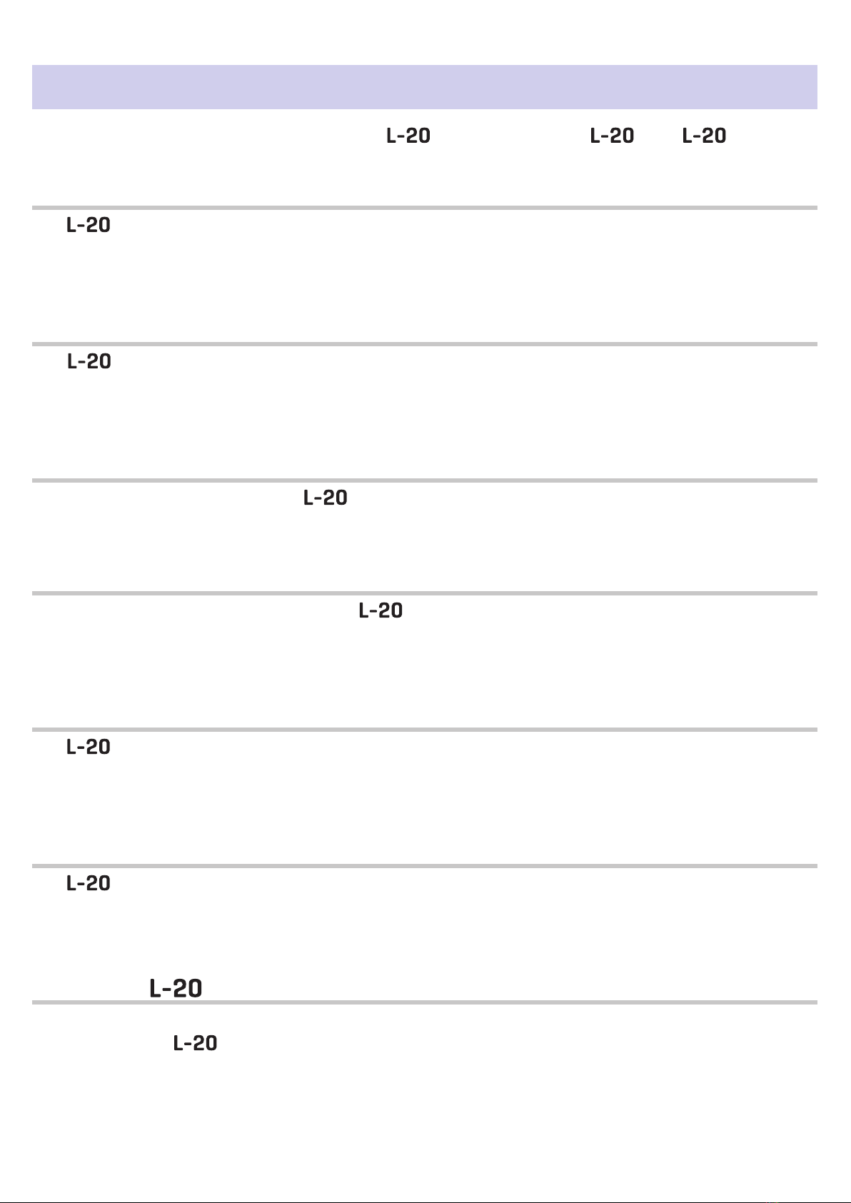
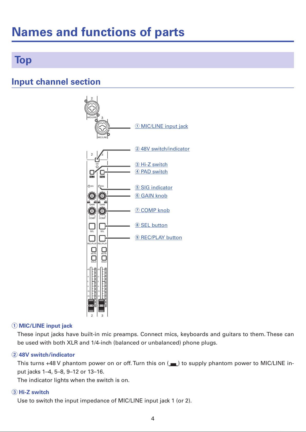
Names and functions of parts …………………… 4
Top ………………………………………………… 4
Rear panel ……………………………………… 19
Equipment connection examples ……………… 21
Live PA system ………………………………… 21
Display overview ………………………………… 23
Home Screen …………………………………… 23
Turning the power on and off ………………… 24
Turning the power on ………………………… 24
Turning the power off ……………………… 26
Using the MENU screen ………………………… 27
Mixer ………………………………………………… 28
Outputting input sounds from output devices
…………………………………………………… 28
Adjusting the tone and panning …………… 30
Using the built-in effects …………………… 31
Using scene functions ……………………… 32
Setting signals output from MONITOR OUT A–F
…………………………………………………… 35
Recording and playback ………………………… 37
Preparing to record …………………………… 37
Recording/overdubbing and playing tracks 39
Adding marks ………………………………… 42
Redoing parts of recordings (punching in/out)
…………………………………………………… 43
Mixing down tracks …………………………… 44
Starting recording automatically …………… 46
Pre-recording before recording starts …… 48
Selecting the folder where projects are saved
…………………………………………………… 49
Selecting projects for playback ……………… 50
Using the metronome …………………………… 51
Enabling the metronome …………………… 51
Changing metronome settings ……………… 52
Using the slate mic ……………………………… 56
Recording with the slate mic ………………… 56
Changing slate mic settings ………………… 57
Projects …………………………………………… 58
Changing project names …………………… 58
Deleting projects ……………………………… 60
Protecting projects …………………………… 61
Checking project information ……………… 62
Saving projects to USB ash drives ……… 63
Importing projects from USB ash drives … 65
Checking, deleting and moving to marks … 67
Audio les ………………………………………… 68
Deleting audio les …………………………… 68
Exporting audio les to USB ash drives … 70
Importing audio les from USB ash drives 72
Using audio interface functions ……………… 74
Installing the driver …………………………… 74
Connecting to a computer …………………… 75
Inputting return signals from the computer to a
stereo channel ………………………………… 76
Using card reader functions …………………… 77
Recording and playback settings ……………… 78
Changing the recording format …………… 78
Changing automatic recording settings …… 79
Showing recording levels on level meters 81
Compensating for latency that occurs during in-
put and output ………………………………… 82
Changing the playback mode ……………… 83
Changing the input signal recording source 83
SD card settings ………………………………… 84
Checking the open space on SD cards …… 84
Formatting SD cards ………………………… 84
Testing SD card performance ……………… 85
Making various settings ………………………… 88
Setting the date and time …………………… 88
Setting the footswitch ………………………… 89
Changing the sampling rate ………………… 90
Disabling the automatic power saving function
…………………………………………………… 91
Adjusting the display contrast ……………… 91
Restoring settings to factory defaults ……… 92
Checking the rmware versions. ……………… 93
Updating the rmware ………………………… 94
Control from an iPad …………………………… 95
Troubleshooting …………………………………… 96
Specications ……………………………………… 98
Send effect specications ……………………… 99
Mixer block diagram ……………………………… 100
3

Names and functions of parts
Top
Input channel section
1MIC/LINE input jack
248V switch/indicator
3Hi-Z switch
4PAD switch
5SIG indicator
6GAIN knob
7COMP knob
8SEL button
9REC/PLAY button
1MIC/LINE input jack
These input jacks have built-in mic preamps. Connect mics, keyboards and guitars to them. These can
be used with both XLR and 1/4-inch (balanced or unbalanced) phone plugs.
248V switch/indicator
This turns +48 V phantom power on or off. Turn this on ( ) to supply phantom power to MIC/LINE in-
put jacks 1–4, 5–8, 9–12 or 13–16.
The indicator lights when the switch is on.
3Hi-Z switch
Use to switch the input impedance of MIC/LINE input jack 1 (or 2).
4

Turn it on ( ) when connecting a guitar or bass guitar.
4PAD switch
This attenuates (reduces) the input signal of the equipment connected to the MIC/LINE input jack by 26
dB.
Turn this on ( ) when connecting line level equipment.
5SIG indicator
This indicator shows the signal level after adjustment by the GAIN knob.
The indicator color changes according to the signal level. Adjust so that it does not light red.
Lit red: Lit red: input signal level is close (−3 dBFS or higher) to the clipping level (0 dBFS)
Lit green: Lit green: input signal level is between −48 dBFS and −3 dBFS compared to the clipping level
(0 dBFS)
6GAIN knob
Use to adjust the input gain of the mic preamp.
The range of adjustment depends on the on/off status of the MIC/LINE input jack switch (Hi-Z on chan-
nels 1–2 or PAD on channels 3–16).
Jack Adjustment range
MIC/LINE input jack 1–2 (XLR) +16 – +60 dB
MIC/LINE input jack 1–2 (TRS) Hi-Z off +16 – +60 dB
Hi-Z on (TS) +6 – +50 dB
MIC/LINE input jack 3–16 PAD off +16 – +60 dB
PAD on −10 – +34 dB
7COMP knob
Use to adjust the amount of compression.
8SEL button
Use to select a channel for parameter adjustment in the channel strip section.
Channels with lit SEL buttons are affected by channel strip section adjustments.
9REC/PLAY button
Use this button to switch between recording input signals to the SD card and playing back an already
recorded le from the SD card.
Status Explanation
Lit red Input signals will be recorded to the SD card.
Lit green
An already recorded le will be played back. Playback signals are input
before the equalizer. In this state, only files are played back. Signals
from input jacks are disabled.
Unlit Files will neither be recorded nor played back.
NOTE
Recorded signals can be set to either before or after the compressor. (→"Changing the input signal re-
cording source")
5

!LINE input jacks (TS)
"LINE input jacks (RCA)
#USB button
$MUTE button
%SOLO button
&Level meter
(Channel fader
!LINE input jacks (TS)
Use these input jacks to connect line level equipment. For example, connect keyboards or audio devic-
es.
These can be used with 1/4-inch (unbalanced) phone plugs.
NOTE
If only the left LINE input jack (TS) channel is connected, it will be handled as a mono channel.
"LINE input jacks (RCA)
Use these input jacks to connect line level equipment. For example, connect audio devices.
These can be used with RCA pin connectors.
NOTE
If both the RCA andTS LINE input jacks are connected, theTS input jacks will be used.
6

#USB button
This switches the signals input to channels 17/18 (or 19/20).
Lit: audio return signal output from the computer
Unlit: LINE input jacks
NOTE
Connect the to a computer as an audio interface. (→"Connecting to a computer")
$MUTE button
This mutes or unmutes signals.
To mute the channel, press this button to light it.
HINT
This has no effect on recording to the SD card.
%SOLO button
When a SOLO button is ON, the pre-fader signal can be heard from the PHONES jack. At such times, the
SELECT knob will automatically select SOLO.
&Level meter
This shows the signal level after adjustment by the channel fader.
Range shown: −48 dB – 0 dB
0 (Clipping level)
-9
-6
-3
-12
-15
-18
-21
-24
-27
-30
-48
(dBFS)
NOTE
If the actual channel fader position differs from the channel fader position recalled using the scene func-
tion, for example, the level meter will show the recalled fader position.
(Channel fader
This adjusts the channel signal level in a range from −∞ to +10 dB.
7

CHANNEL STRIP section
4MID FREQ knob
5MID knob
6LOW knob
!EQ OFF button
3HIGH knob
1SEND EFX1 knob
2SEND EFX2 knob
8LOW CUT knob
7PAN knob
9Φ(polarity) button
1SEND EFX1 knob
The amount that can be sent to the SEND EFX 1 bus can be set from −∞ to +10 dB.
2SEND EFX2 knob
The amount that can be sent to the SEND EFX 2 bus can be set from −∞ to +10 dB.
3HIGH knob
This adjusts the boost/cut of high-frequency equalization.
Type: shelving
Gain range: −15 db – +15 dB
Frequency: 10 kHz
4MID FREQ knob
This adjusts the central frequency of the mid frequency equalization.
Frequency: 100 Hz–8 kHz
Frequency guide
140 5.4k
100 8k
3.7k
2.5k
1.7k
1.2k
200
280
400
570
800
5MID knob
This adjusts the boost/cut of mid-frequency equalization.
Type: peaking
Gain range: −15 db – +15 dB
Frequency: set by MID FREQ knob
8

6LOW knob
This adjusts the boost/cut of low-frequency equalization.
Type: shelving
Gain range: −15 db – +15 dB
Frequency: 100 Hz
7PAN knob
This adjusts the position in the stereo output bus.
On a stereo input channel, this adjusts the volume balance between the left and right channels.
8LOW CUT knob
This adjusts the high-pass lter, which cuts low frequencies. Signals below the set frequency are atten-
uated 12 dB/octave.Turning the LOW CUT knob left so that all the LEDs around it become unlit turns off
the LOW CUT.
Frequency: OFF, 40–600 Hz
Frequency guide
140 5.4k
100 8k
3.7k
2.5k
1.7k
1.2k
200
280
400
570 800110
600
40
50
60
70
90 150
190
260
340
450
9Φ(polarity) button
This reverses the polarity of the selected channel.
!EQ OFF button
When this button is lit, HIGH, MID, LOW and LOW CUT are bypassed.
9

FADER MODE section
1MASTER and A–F buttons
These switch between the mixes output from the MASTER OUT and MONITOR OUT A–F jacks.
MASTER button: Use to show and adjust the mix output from the MASTER OUT jacks.
A–F buttons: Use to show and adjust the mixes output from the MONITOR OUT A–F jacks.
NOTE
The following parameters can have separate settings for the MASTER and A–F mixes.
- Fader positions (each channel)
- EFX1/2 RTN positions
10

Send effect (SEND EFX) section
1Effect type 2 list
1Effect type 1 list
2EFX2TYPE knob
2EFX1TYPE knob
3Parameter 2 knobs
3Parameter 1 knobs
4MUTE button
5SOLO button
6EFX RTN level meters
7EFX RTN fader
1Effect 1/2 type lists
These are lists of the built-in effects. The effects are separated into two sets, and one effect from each
set can be used.
The names of the currently selected effects light. An effect name blinks when being selected.
If some time passes without a different effect being selected, the previously selected effect will remain
selected.
2EFX1/EFX2 TYPE knobs
Use to select the built-in effects.
Turn these knobs to select effect types, and press them to conrm.
11

3Parameter 1 and 2 knobs
Use these to adjust the parameters for the selected effects.
See "Send effect specications" for the parameters of each effect.
4MUTE button
This mutes or unmutes the signal sent from the built-in effect.
To mute the channel, press this button to light it.
5SOLO button
When a SOLO button is ON, the signal before the EFX 1/2 RTN fader can be heard from the PHONES
jack. At such times, the SELECT knob will automatically select SOLO.
6EFX RTN level meters
These show the levels of the signals sent from the built-in effect to the master bus after adjustment by
the EFX RTN fader.Their range is from −48 dB to 0 dB.
7EFX RTN fader
This adjusts the levels of the signals sent from the built-in effect to the master bus in a range from −∞
dB to +10 dB.
NOTE
If the actual channel fader position differs from the channel fader position recalled using the scene func-
tion, for example, the level meter will show the recalled fader position.
12

SCENE section
1ON button
2RESET button
31–9 buttons
4RECALL button
5SAVE button
1ON button
Press this button, lighting it, to use the scene function
2RESET button
Press this button to reset the current mixer settings to the factory defaults.
31–9 buttons
Use these buttons to select the scene to use to save the current mixer settings and to load saved
scenes.
If the current mixer settings match the settings of a scene, the corresponding number button will light.
This unit can save up to 9 scenes.
4RECALL button
Use this button when loading scenes saved to buttons 1–9.
When this button is pressed, buttons 1–9 will blink if they have saved scenes and be unlit if they do not.
To recall a saved scene, press a blinking button between 1 and 9. To cancel recalling a scene, press the
RECALL button again.
5SAVE button
Use this button when saving the current mixer settings to a scene.
When this button is pressed, buttons 1–9 will light if they have saved scenes and blink if they do not.To
save a scene, press a button between 1 and 9 to save it to that number. To cancel saving a scene, press
the SAVE button again.
13

Output section
1MASTER OUT jacks
2
MONITOR OUT A–F jacks
3
MONITOR OUT A–F knobs
6SELECT knob
7VOLUME knob
8PHONES jack
9MASTER REC/PLAY button
4
MONITOR OUT A–F switches
5
MONITOR OUT A–F
PHONES/SPEAKER switches
!MASTER MUTE button
"Master level meters
#Master fader
1MASTER OUT jacks
These jacks output signals after volume adjustment by the master fader.
Connect them to a power amplier, a PA system or speakers with built-in ampliers, for example.
These support balanced output with XLR connectors (2 HOT).
2MONITOR OUT A–F jacks
These jacks output signals after volume adjustment by the MONITOR OUT A–F knobs.
Connect monitor speakers or headphones for performers here.
These support balanced 1/4-inch phone jack output.
NOTE
• The MONITOR OUT A–F jacks can be set to output the same signals as the MASTER OUT jacks or the
signals set separately in the fader mode section. (→"Setting signals output from MONITOR OUT A–F")
• Set the MONITOR OUT A–F PHONES/SPEAKER switch according to the type of connected equipment.
14

3MONITOR OUT A–F knobs
Use to adjust the volumes of the signals output from the MONITOR OUT A–F jacks.
4MONITOR OUT A–F switches
These switch the signals output from the MONITOR OUT A–F jacks.
Status Explanation
MASTER ( ) The signal after adjustment by the master fader will be output.
A–F ( ) The signals set in the FADER MODE section are output.
5MONITOR OUT A–F PHONES/SPEAKER switches
Use these to select the type of equipment connected to the MONITOR OUT A–F jacks.
Status Explanation
( ) Select this when headphones are connected. A stereo signal is output from the
MONITOR OUT A–F jack.
( ) Select this when speakers are connected. A mono balanced signal is output from
the MONITOR OUT A–F jack.
6SELECT knob
Use this to select the signal output from the PHONES jack.
The options are MASTER, SOLO and MONITOR OUT A–F.
Status Explanation
MASTER The same signals as the MASTER OUT are output.
A-F The signals set in the FADER MODE section are output.
SOLO The signals of SOLO enabled channels are output.
NOTE
When a SOLO button is activated, this knob will also automatically select SOLO. At such times, changing
the output with the SELECT knob will cancel soloing.
7VOLUME knob
Use this to adjust the volume of the PHONES jack.
8PHONES jack
Connect headphones here.
9MASTER REC/PLAY button
Use this button to switch between recording the signal input on the master bus to the SD card and play-
ing back an already recorded le from the SD card.
Status Explanation
Lit red The signal will be recorded to the SD card after adjustment by the master fader.
Lit green The playback signal of a le is inserted on the master bus.The REC/PLAY buttons
of other channels will be unlit at this time.
Unlit Files will neither be recorded nor played back.
!MASTER MUTE button
This mutes or unmutes the MASTER OUT jacks.To mute the channel, press this button to light it.
"Master level meters
These show the signal levels output from the MASTER OUT jacks in a range from −48 dB to 0 dB.
15

#Master fader
This adjusts the signal levels output from the MASTER OUT jacks in a range from −∞ to +10 dB.
NOTE
If the actual channel fader position differs from the channel fader position recalled using the scene func-
tion, for example, the level meter will show the recalled fader position.
When AUTO REC is activated, however, the master fader position will not be shown.
16

RECORDER section
1Slate mic
7STOP button
#REW button
"FF button
2SLATE button/indicator
3Display
4MENU button
5Selection encoder
6TEMPO button/indicator
8
PLAY/PAUSE button/in-
dicator
9REC button/indicator
!
OVER DUB button/indicator
1Slate mic
This is a built-in mic for recording comments.
This mic input is active while the SLATE button is being pressed.
It can be set to record on channels 1–20, the MASTER channel or all channels. (→"Changing the slate
mic routing")
2SLATE button/indicator
This activates the slate mic.
The slate mic is activated while this button is being pressed and its indicator is lit.
3Display
This shows the recorder status and MENU screen.
4MENU button
This opens the menu.
5Selection encoder
Use this to change menus and values and to move between items.
Operation Result
Turn when Home Screen open Search forward or backward in one-second increments.
Press when Home Screen open Set a mark.
Turn when menu open Move between parameters and change values.
Press when menu open Conrm parameter value.
6TEMPO button/indicator
This sets the tempo of the metronome built into the recorder.
Press this button to make the recorder detect the tempo from the average value.
The indicator blinks at a tempo of 40.0–250.0 bpm during recording, playback and when one of the fol-
lowing effects that synchronize with tempo is selected.
Effects that synchronize with the tempo: Delay, Analog, P-P Dly
Metronome settings (→"Changing metronome settings")
17

7STOP button
This stops the recorder.
8PLAY/PAUSE button/indicator
This starts and pauses recorder playback.The indicator shows the playback status as follows.
Status Explanation
Lit green The recorder is playing back.
Blinking green Playback is paused.
9REC button/indicator
This puts the recorder in recording standby.The indicator shows the recording status as follows.
Status Explanation
Lit red The recorder is recording or in recording standby.
Blinking red Recording is paused.
!REW button
Press to move to the previous mark.
If no mark is set, this moves to the beginning. Press this button when at the beginning to move to the
previous project.
Press and hold to search backward. (The longer you press, the faster the speed becomes.)
"FF button
Press to move to the next mark.
If it is the last mark, this moves to the end of the le. Press this button again to move to the next project.
Press and hold to search forward. (The longer you press, the faster the speed becomes.)
#OVER DUB button/indicator
Status Explanation
Lit (ON) Record by overwriting into the current project folder.
Unlit (OFF) Create a new project folder and make a new recording.
18

Rear panel
1POWER switch
2DC IN 12V AC adapter connector
3USB HOST port
4MODE switch
5USB DEVICE port
6
CLASS COMPLIANT MODE
switch
7SAMPLE RATE switch
8SD card slot
9CONTROL IN jack
!REMOTE jack
1POWER switch
This turns the unit on and off.
Switch to — to turn the power on. Switch to to turn the power off.
When the POWER switch setting is changed to OFF, the current mixer settings are automatically saved
in the unit and in the settings le in the project folder on the SD card.
2DC IN 12V AC adapter connector
Connect the included AC adapter here.
3USB HOST port
This USB 2.0 HOST port is for connecting USB ash drives.
Projects and audio les can be saved on and loaded from connected USB ash drives.
4MODE switch
Set whether to use as a USB HOST, card reader or audio interface.
This cannot be changed after starting up.
5USB DEVICE port
This USB 2.0 port is for connecting with a computer.
It will start up as a card reader or audio interface, depending on the MODE switch selection.
Card reader mode
Operating as an SD card reader, data can be exchanged with a computer.
Audio interface mode
Operating as an audio interface, audio data can be exchanged with a computer.
Inputs: The signals from channels 1–20 after they pass through their compressors and the master fader
output signals are input to the computer.
Outputs: Outputs from the computer can be assigned to channels 17/18 and 19/20.
Use when connected to an iOS device is possible if the CLASS COMPLIANT MODE switch is set to ON.
19
Other manuals for LiveTrak L-20
2
Table of contents
Other Zoom Music Mixer manuals
Popular Music Mixer manuals by other brands

YORKVILLE
YORKVILLE MM-6 owner's manual

audiophony
audiophony MX44 user guide

Quest Engineering
Quest Engineering Q-Tech Commercial QT ZM66 user manual

Phonic
Phonic PM801 user manual

Gates Radio Company
Gates Radio Company DUALUX II M6542-A Instruction book

Tormach
Tormach PATHPILOT OPERATOR CONSOLE installation guide