ZORA P1 User manual

1
Zora P1 DEVELOPMENT BOARD
Zora P1 V1.0
電波法により5GHz帯は屋内使用に限ります

2
目录
Orbbec Pi 2(A311D)Development board help document.......................................................1
1. Orbbec Pi P2(A311D-4G-01 )Introduction of Development Board Interface............. 3
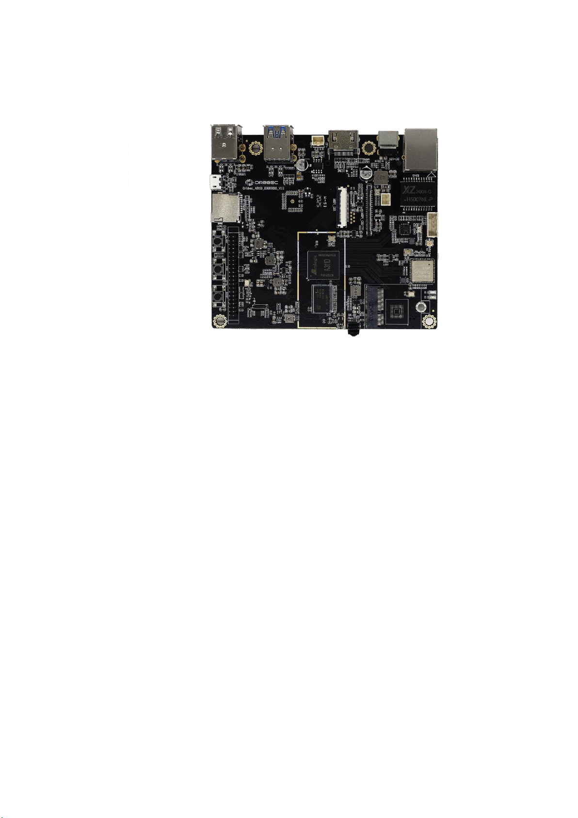
1.1 Front picture of development board................................................................................ 3
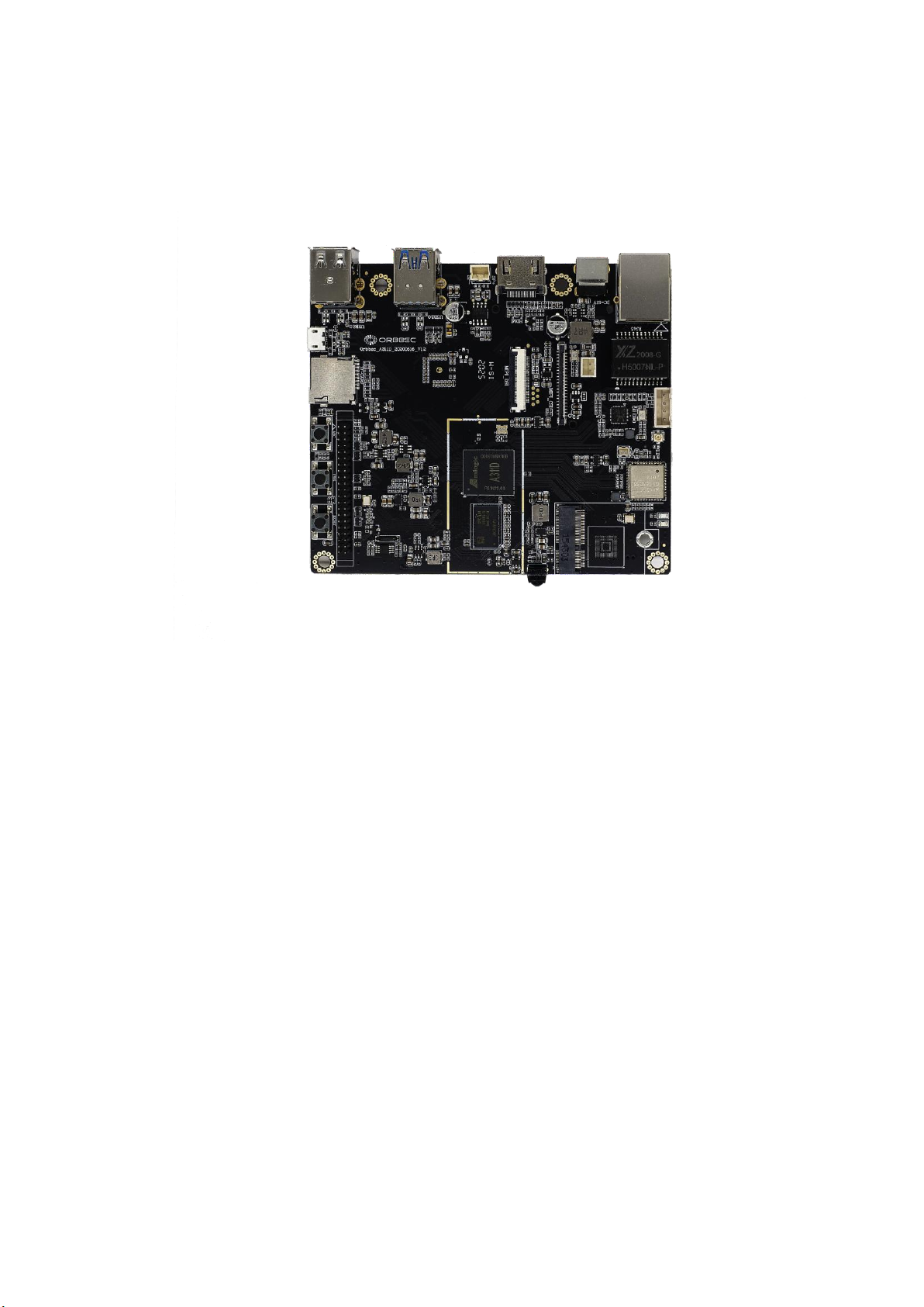
1.2 Back picture of development board................................................................................. 3
1.3 Introduction to hardware interface............................................................................. 3
1.4 42Pin GPIO introduction (form 01 to 42)....................................................................5
1.5 Uart introduction(from 01 to 04)........................................................................... 5
1.6 PMD introduction(from 01 to 04).......................................................................... 5
1.7 RTC introduction............................................................................................................5
2. Preparation for firmware burning............................................................................................7
2.1 Long press “update” button enter burn mode................................................................ 7
2.2 Use hardware interface uart-debug enter burning mode:.............................................9
2.3 Use ADB tool to enter burning mode.............................................................................10
3. Detailed method and operation steps of disassembling and burning firmware............. 11
3.1 Configuration requirements for computers:............................................................... 11
3.2 Using the update button to burn the firmware............................................................. 11
3.4 Use hardware interface uart-debug enter burning mode........................................... 16
3.5 Burn firmware with ADB tool........................................................................................... 17
3.6 Burn the firmware to multiple development boards at the same time...................... 19
3.7 Download burning tools...................................................................................................19
5. Set ADB debugging................................................................................................................ 20
6. EMMC extension module instructions.................................................................................. 20
7. POE Module introduction.......................................................................................................21
8. NPU help.................................................................................................................................. 23
9. Hardware data of development board................................................................................. 24
10. Firmware Download............................................................................................................26
11. Accessories around development board..........................................................................27

3
1. Zora P1(A311D-4G-01 )Introduction of Development Board Interface
1.1 Front picture of development board
1.2 Back picture of development board
1.3 Introduction to hardware interface
processor
Amlogic, Quad A73+ Dual A53

4
RAM
2GB DDR4*2
storage
32GB EMMC
EMMC extension
Pluggable EMMC module(8GB,16GB,32GB)
Storage-Micro SD
Up to 128Gb
MIPI-CSI
1 CSI + 8M HDR ISP
MIPI-DSI
Support
USB
2xUSB 3.0 + 2xUSB 2.0 + 1USB XHCI OTG 2.0
HDMI
HDMI 2.1
Wifi/BT
WIFI 2.4/5G 802.11a/b/g/n/ac, 2x2 MIMO,BT5.0
10m
Ethernet
RJ45 GigE Vision
POE
Pin + Extra Cap
Microphone
On-board
PDM
PDM interface microphone
Debug
Micro USB
Buttons
Power ,Reset,ADC ,Update and act
OPEX Wifi
LED
Power status indicator
42Pin GPIO
Detail in 42Pin GPIO introduction
UART
1
I2C
2
SPI
2
I2S
1
PWM
2
ADC
1
DC-OUT
1x5V+1x3.3V
GPIO
8
Ground
8
PMU
YK613
DC-IN
12V 2.1mm
OS
Android 9,Ubuntu 18.04,Linux 4.9
Replace firmware
By replacing the EMMC module
Upgrade mode
USB update,

5
1.4 42Pin GPIO introduction (form 01 to 42)
TX(01)
RX
GND
S_M0
S_M1
S_CS
S_CK
GND
I_MCK
I_SCK
I_LR
I_DO
GND
GPIO1
GPIO2
GPIO3
GPIO4
GND
PWM2
5V
5V
SDA
SCL
SDA2
SCL2
GND
P_D1
P_D0
P_SY
P_CK
GND
GCLK
32K
GND
GPIO5
GPIO6
GPIO7
GPIO8
GND
PWM1
3.3V
3.3V(42)
1.5 Uart introduction(from 01 to 04)
3.3V(01)
RX
TX
GND(04)
1.6 PMD introduction(from 01 to 04)
3.3v
(01)3.3v GND PDM_DCK GND PDM_DIN0 PDM_DIN1 GND
(07)
1.7 RTC introduction
GND(01)VBAT(02)

6
1.8 Product size description
116*100mm

7
2. Preparation for firmware burning
There are three ways to enter burn mode:
2.1 Long press “update” button enter burn mode
a.Long press update button

8
b.Connect the OTG interface of development board through windows(win 10 or win7)
system computer

9
c.Link power 12V-2A adapter through DC-in interface
d.Successfully linked the burning software。
2.2 Use hardware interface uart-debug enter burning mode:
a. Using USB to UART serial port tool connect the UART-debug interface
b. Through serial protocol tool software ,type in “reboot”
c. When the development board is restarted, Press enter continuously and ente
uboot mode
d.type in “update”
e. Successfully linked the burning software

10
2.3 Use ADB tool to enter burning mode
a. Power on the development board by connecting the power adapter
b. Open the computer CMD console
c. Connecting computer and development board with the otg interface
d.CMD console type in “adb reboot update “
e. Successfully linked the burning software

11
3. Detailed method and operation steps of disassembling and burning firmware
3.1 Configuration requirements for computers:
a. Windows 7 or windows 10 operating system
b.Turn off antivirus software
c.has a high-speed USB 2.0 or USB 3.0 interface
3.2 Using the update button to burn the firmware
a.Long press the update button development board
b.Using micro USB cable to connect OTG hardware interface
c.Open the software “USB burning 2.2. X”

12
c.1 software interface(English)
d. Supply power to development board through power supply adaptation
e. Burning tool successfully connected to development board

13
e.2 Software interface(English)
f. Import firmware(x.img)

14
f.2 Software interface(English)
g. Click the start button,enter burning state

15
g.2 Software interface(English)
h. Complete firmware burning

16
h.2 software interface (English)
i.Clike the stop button then close the software
3.4 Use hardware interface uart-debug enter burning mode
a. Using USB to UART serial port tool connect the UART-debug interface
b. Through serial protocol tool software ,type in “reboot”
c. When the development board is restarted, Press enter continuously and ente
uboot mode
d.Type in “update”
e. Burning tool successfully connected to development board

17
f.import the firmware
g.click the Start button, then waiting for burning
h. Complete firmware burning
i.Click the stop button ,close the tools
3.5 Burn firmware with ADB tool
a. Power on the development board by connecting the power adapter
b. Open the computer CMD console

18
c. Connecting computer and development board with the otg interface
d. CMD console type in “adb reboot update “
e. Successfully linked the burning software
f.Import the burning firmware
g.Click the start button,then waiting for burning
h.Buring the firmware successful
i.Click the stop button and close the Burning tools

19
3.6 Burn the firmware to multiple development boards at the
same time
1. Using USB hub with power supply
2. Use the same operation as step 3.2
3. Support two or more development boards to be burned at the same time
3.7 Download burning tools

20
5. Set ADB debugging
5.1 Android operating system on
a. The development board supports ADB debugging by default , Connect directly
through OTG interface。Before connect otg ,make sure the computer has an ADB
driver installed。
b. Open terminal window and type in adb shell
6. EMMC extension module instructions
6.1 EMMC EMMC pluggable expansion module , Capacity of hard disk is 8GB
(Customizable capacity 16GB,32GB,64GB)
6.2 EMMC module Dimension drawing
Table of contents