9
Quick change system for SPRINT Series
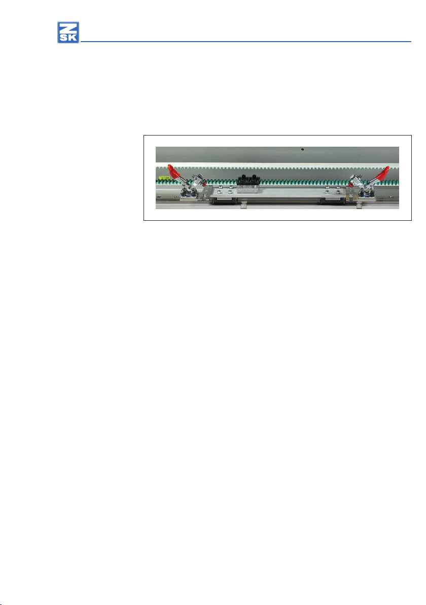
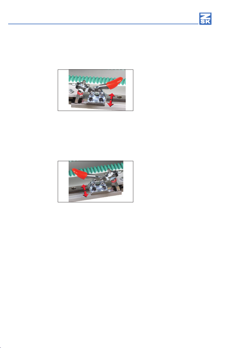
Fig. 11: Horizontal clamping xture assembled, carriage (view from above)
Mount the two pre-assembled clevises with the horizontal clamping xture on the
carriage. Observe the mounting direction of the horizontal clamping screw.
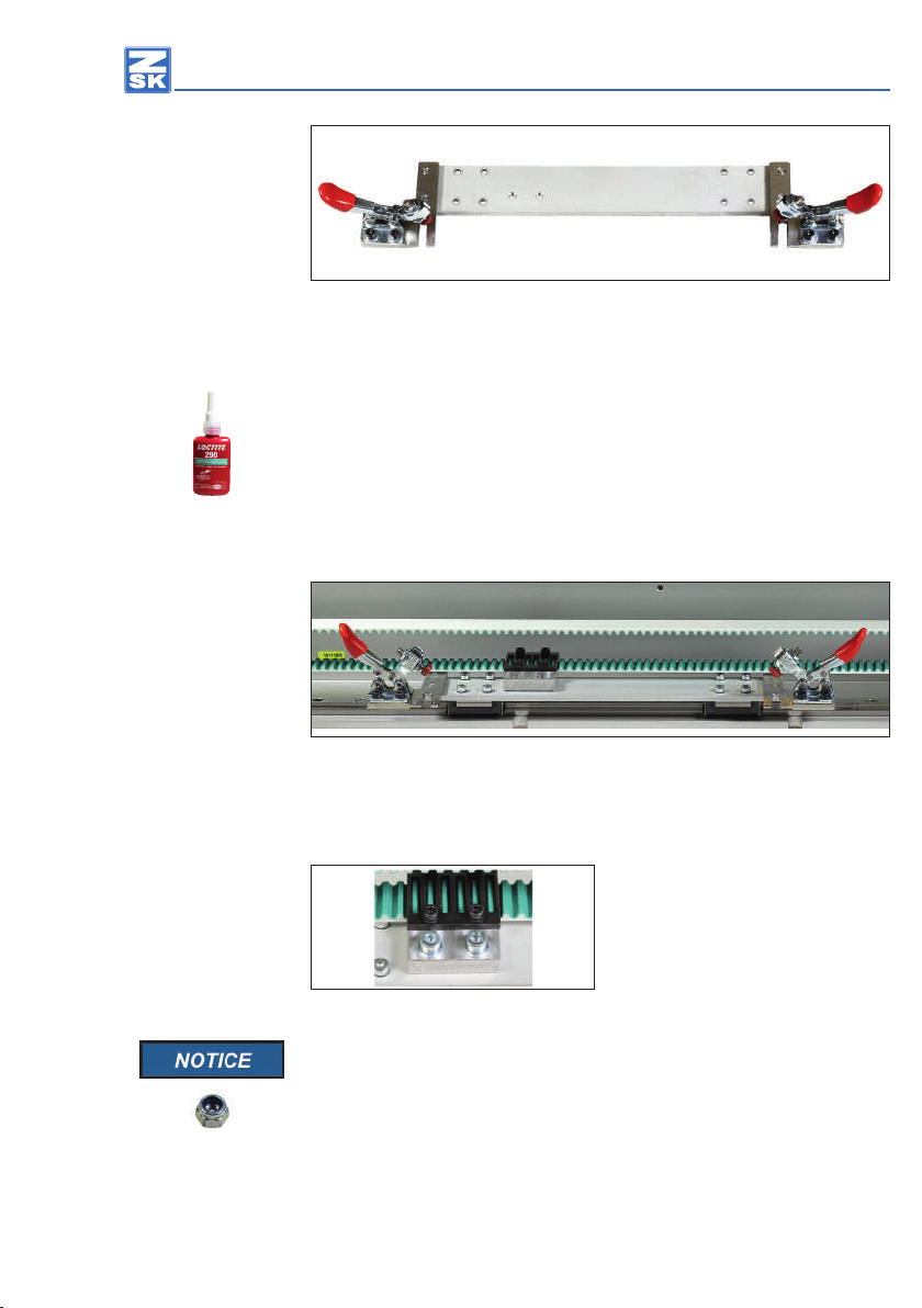
Rotate the mounting screws ca. 1 turn in the thread.
Place a drop of Loctite 290 (or equivalent adhesive from another manufacturer)
on the threads of the 4 mounting screws.
Only tighten the two screws securing the individual clevises rmly after both
countersunk head of the screws are sitting in the intended cuts.
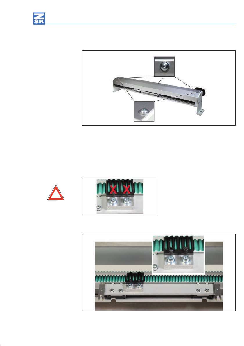
Fig. 12: Carriage, assembly
Assemble the carriage with the 8 mounting screws (incl. locking washer) on the
two movable pilot cariages of the pantograph drive for lateral movement.
Secure the connection with the two
screws incl. the washer on the carriage.
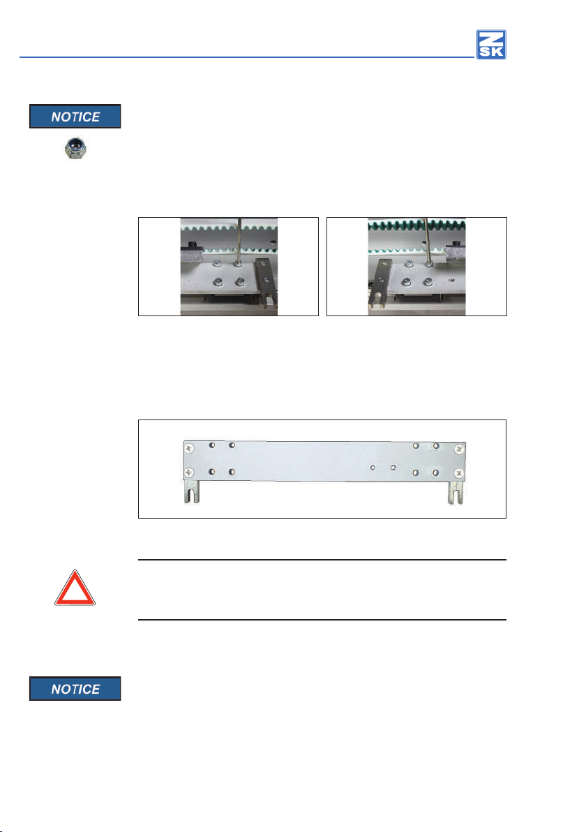
Fig. 13: Connection, assembly
On the bottom of the carriage the screw connection is countered by
2 lock nuts.
For securing the connection, screw the two lock nuts from below rmly on the
screws.
ÖSo the transmission of motion of the pantograph drive for lateral
movement is established again.