8 9
Product Overview Specications
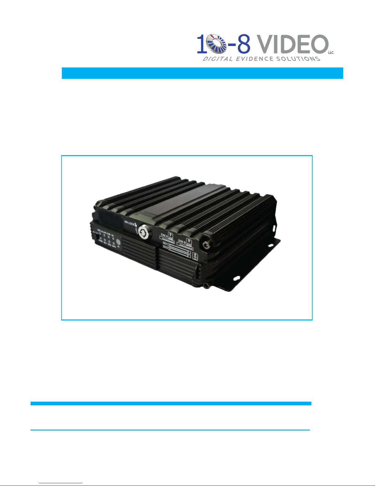
Product Description
The10-8HD4SDisadualSDcardHDMDVRespeciallydesignedforuse
invehicles.Iffeaturesfour(4)channelsofD1/960H/720Pvideoandaudio
recordingandplayback,four(4)channelsofAHD720Pandonechannel
ofIPCHDvideoviaafullframerecordingcamera.Italsoutilizesoneof
themostadvancedH.264videoencoding/decodingcodecsintheindustry
today.
ThemobileMDVRispoweredbyanARMDSPfastdual-coreprocessor
runningonanembeddedLinuxOS.Italsofeatures3G/4Gnetwork
capabilities,GPS,WiFi,fail-safeprotection,HDDshockabsorption,HDD
heatingandawidevoltagerange.
Allofthesefeatures,alongwithitseasy-to-useandpowerfulinterface
software,givesthe10-8HD4SDexcellentfunctionality,scalability,stability
andmakesitagreatvalue.Proofofthisisitsextensiveuseinpublicbuses,
logisticvehicles,schoolbuses,policecars,nancialconvoytrucksandfuel
tankers.
Features
• H.264videocompressionencodingsupported,PAL:100fps@AHD720P
• 4ChannelsofD1/960H/AHD720Psimultaneousaudio&videorecording/replay.
• 4-wayAHD720P&1-wayIPC1080PHDcamerawithfull-framerecording.
• Aircushioningsystemprovidingreliabilityandstronganti-shockproperties.
• 8-seconddelayrecordingincaseofpowerfailure.
• Builtin3G/4Gnetwork,GPSWiFi(optional)
• Supportstwo(2)SDcards-each128GBcapacity.
• Scaleswellwith1RS485interfaceand2RS232interfaces.
• 8V-36Vwidevoltagesupply,12VPOEpowersupplysupported
• Goodshockresistance,easyinstallationand360°installationsupported.
• High/lowtemperatureresistant,operatesfrom-13°Fto+158°F.
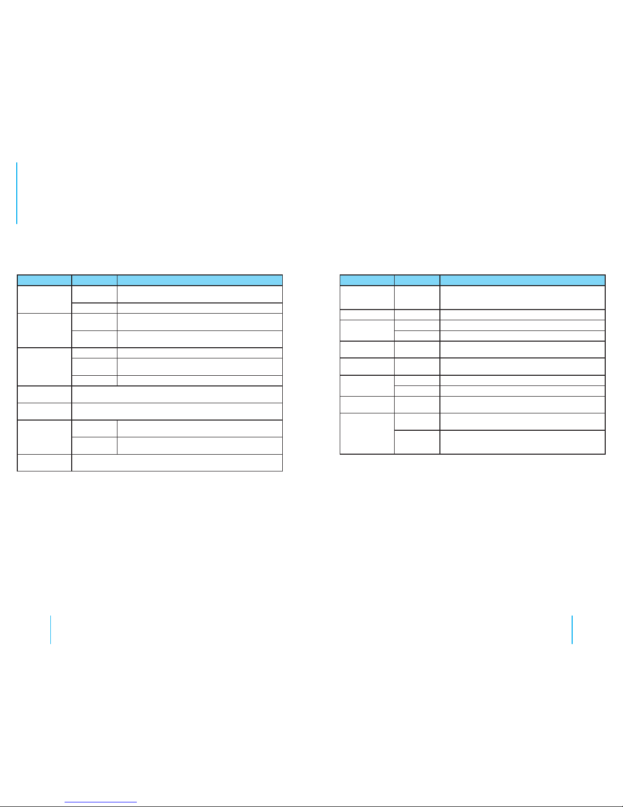
Technical Specications
Item Parameter Description
System
Language English
Operating
Interface Graphical user interface
Password
& Security User password and Admin password management
Video
Video Input
• 4-channel analog video input
• 4 available channels of D1/960H/AHD 720P composite video
inputs
• Or 4 composite video inputs
Video Output 2 Video outputs (1 - φ3.5 phone jack & 1 - 24PIN connector)
Video Display 1~4 Screens supported
Video Standard PAL or NTSC
Image
Compression H.264 encoding supported , PAL: 100fps@AHD 720P
Audio
Audio Input 4 Audio inputs
Audio Output 2 Audio outputs (1 - φ3.5 phone jack & 1 - 24PIN connector)
Recording
Mode Synchronous video & audio recording
Image
Processing
and Storage
Local
Recording Resolution D1/960H/720P optional
Network
Transmission Resolution CIF/QCIF optional
Video
Streaming
Standard
ISO14496-10
Video Code
Rate
CIF: 1536Kbps~128Kbps
D1: 2048Kbps~400Kbps
960H: 2048Kbps~400Kbps
720P: 4096Kbps~400Kbps
Eight (8) picture quality levels are available with level 1 being the
highest and level 8 being the lowest
Audio Bit Rate 8Kb/s
Storage Two SD cards supported, 128GB for each
Specications