1A Profi Handels AQUA-21 User manual

PRESSCONTROL / FLOW GUARD
DURCHFLUSSWÄCHTER
INSTRUCTION MANUAL
BEDIENUNGSANLEITUNG
AQUA-21-Automatic-Controller
(PS01109)

Inhaltsverzei hnis
1. Vorwort 2
2. Allgemeines 2
3. Installation 2
4. Verfahren für die In etrie setzung 2
5. Sicherheitshinweise 3
6. Wartung 3
7. Gesetzliche Gewährleistung 3
8. Erkennen und Behe en von Fehlern 3
9. Technische Daten 7
10. Elektrischer Anschlussplan 7
Impressum
1A Profi Handels Gm H
www..profi-pumpe.de
Email: [email protected]
Tel.: (+49) 0611-945877600
Fax: (+49) 0611-9458776911
DEUTSCH
1

1. Vorwort
Zu dem Kauf unserers Durchflusswächters möchten wir Sie recht herzlich eglückwünschen. Wir wissen Ihr
Vertrauen zu schätzen. Aus diesem Grund stehen ei uns Funktions- und Betrie ssicherheit an erster Stelle.
2. Allgemeines
Der AC 21 wird für Anlagen empfohlen, in denen das durchfließende Wasser ohne A lagerungen/schmutzfrei
ist. Im gegenteiligen Fall muss ein Filter am Einlauf zum Gerät einge aut werden.
DIESE ANLEITUNG VOR DER INSTALLATION UND DER INBETRIEBNA ME GENAU LESEN
UND BEFOLGEN
3. Installation
1. Das Gerät an einem elie igen Punkt zwischen dem Auslass der Pumpe und dem ersten A nehmer
installieren. Achten Sie auf die Fließrichtung und stellen Sie sicher, dass die hydraulischen
Ver indungen vollkommen dicht sind. Falls eine Pumpe mit Höchstdruck ü er 10 ar enutzt wird,
muss ein Druckreduzierer am Eingang des Gerätes installiert werden.
2. Für den Elektroanschluss des AC 21-Geräts ohne vormontierte Ka el itte stets nach dem
elektrischen Plan (siehe Pkt. 10) vorgehen. Falls ein Ver raucher (Pumpe) mit einer Leistung ü er
1,1 kW verwendet wird und die Raumtemperatur höher als 25°C ist, müssen Ka el mit
Wärme eständigkeit nicht unter 99°C für die Verdrahtung verwendet werden. Für die Verdrahtung
ausschließlich die dazu estimmte Zange enutzen. Bei der Ausführung inkl. mitgelieferter
Anschlusska els genügt es, den Netzstecker der Pumpe mit der Steckdose des AC 21 zu ver inden
und den Netzstecker des AC 21 an eine Steckdose des Stromnetzes anzuschließen.
3. Der Druck, ei dem das AC 21-Gerät einschaltet, ist auf 1,5 ar voreingestellt, dieser Druck ist für
die meisten Anwendungen optimal. Er kann durch einen Fachmann mittels der Einstellschrau e am
o eren Ende verändert werden.
4. Die Höhe der Wassersäule ü er dem AC 21 sollte nicht ü er 15m etragen.
ACHTUNG: FÜR EINEN KORREKTEN BETRIEB DES AC 21 MUSS DER MINDESTDRUCK DER
PUMPE 2 BAR SEIN.
4. Verfahren für die Inbetriebsetzung
SOLLTE DER ANSAUGWASSERSTAND UNTER EINBAUHÖHE DER PUMPE SEIN, IST EIN
ANSAUGROHR MIT BODEN-/RÜCKSCHLAGVENTIL ZU INSTALLIEREN, WELCHES DAS FÜLLEN
DER PUMPE BEI DER ERSTEN INBETRIEBSETZUNG GESTATTET UND IHR ENTLEEREN BEIM
ANHALTEN VERHINDERT.
•Vor der In etrie setzung das Ansaugrohr und die Pumpe ganz füllen und dicht mit dem AC 21
verschrau en.
•Pumpe an den AC 21 elektrisch anschließen (siehe Pkt. 10). Achten Sie da ei auf die Verschrau ung
der A deckklappe am Gehäuse.
WIC TIG: Elektrischen Anschluss nur von einem Fachmann ausführen lassen!
•Öffnen Sie den Wasserhahn auf der Ver raucherseite des AC 21.
•AC 21 an das Stromnetz anschließen, die Pumpe schaltet an.
•Wenn das Wasser aus dem offenen Wasserhahn fließt, kann man diesen schließen.
•Nach ca. 10 – 15 s schaltet der AC 21 die Pumpe a .
•Ü erprüfen Sie nochmals das System auf Dichtigkeit.
•Die In etrie setzung ist erfolgreich eendet, wenn die Pumpe ohne zu takten im Dauer etrie ar eitet
sowie ei Erreichen eines Mindestdrucks die Pumpe a schaltet. Den Test-Vorgang mehrfach
wiederholen.
Zwischen der Pumpe und dem AC 21 sollte kein zusätzliches Rückschlagventil installiert werden, da dies
gelegentlich zu Problemen führen kann.
2
DEUTSCH

5. Sicherheitshinweise
Um elektrische Schläge zu vermeiden und Brandgefahr vorzu eugen, ist das Folgende genauestens zu eachten:
•Aktuell geltende Vorschriften und Normen sind stets zu eachten
•Das Gerät vor jedem Eingriff vom Stromnetz trennen
•Sicherstellen, dass die Anschlussleitung an das Stromnetz und eventuelle Verlängerungen einen
Ka elquerschnitt ha en, der für die Leistung der Pumpe geeignet ist, sowie das die elektrischen Anschlüsse
nicht vom Wasser erreicht werden können.
•Kann Wasser mit elektrischem Strom in Berührung kommen (Pumpen von Wasser, Einsatz in Feuchträumen
wie Bad, Schwimm ädern, Teich, Brunnen) ist immer einen automatischer Differentialschalter (FI) mit
lDn=30mA zu verwenden.
•Gerät nicht dauerhaft in der Sonne etrei en (Ü erhitzungsgefahr).
•Installation nur in frostsicheren Bereichen ohne Kondensat ildung
ACHTUNG: VOR JEDEM EINGRIFF BZW. BEI WARTUNGSARBEITEN, DIE UNTER DRUCK STEHENDEN
LEITUNGEN DURCH ÖFFNEN EINES WASSERHAHNS DRUCKLOS MACHEN.
6. Wartung
Es kommt gelegentlich vor, dass Schmutz im internen Rückschlagventil hängen lei t und dieses nicht mehr 100%-ig a dichtet.
Als erste A hilfe sollte immer versucht werden, das Rückschlagventil frei zu spülen. Dazu wird z. B. der gartenseitige
Wasserhahn voll aufgedreht, so dass die Pumpe ca. 30 Minuten auf voller Leistung Wasser fördert. Ist anschließend das Takten
nicht weg, ist das Gerät zu tauschen. Vor dem Ein au des neuen Gerätes, ist die Pumpe in jedem Fall wie vorher eschrie en,
frei zu spülen. Das Öffnen des Gerätes am Rückschlagventil ist unzulässig und führt stets zum Verlust der ggf. estehenden
Garantieansprüche. Darü er hinaus können erhebliche Gefahren eim Betrie einer taktenden Pumpe entstehen, so dass die
Pumpe unter keinen Umständen weiter etrie en werden darf. Bis zum Geräteaustausch ist die Pumpe außer Betrie zu setzen.
Folgende Kontrollen sollten regelmäßig durchgeführt werden:
•Unversehrtheit des Stromka els
•Sau ere Führung der Leitungen (z.B. keinen Knick)
•Sau erkeit des Mediums
7. Gesetzliche Gewährleistung
Für alle Fa rikations- und Materialfehler gewähren wir die gesetzliche Gewährleistungszeit (neue und unge rauchte Ware). Im
Falle einer Defektes ü ernehmen wir den Umtausch oder die Reparatur des Geräts. Für einen kostenfreien Rückversand itten
wir Sie, Ihr Service-Anliegen ü er unsere Service-Plattform zu schildern. So ha en wir gleich alle Daten und können den
Vorgang schneller ear eiten. http://www.profi-pumpe.de/service.php
Die Gewährleistung gilt nicht ei:
1. Materialverschleiß
2. Un erechtigten Eingriffen oder Veränderungen an dem Gerät
3. Beschädigungen durch Sel stverschulden
4. Unsachgemäßer Wartung und unsachgemäßem Betrie
5. wir leisten keinerlei Schadensersatz für Folgeschäden!
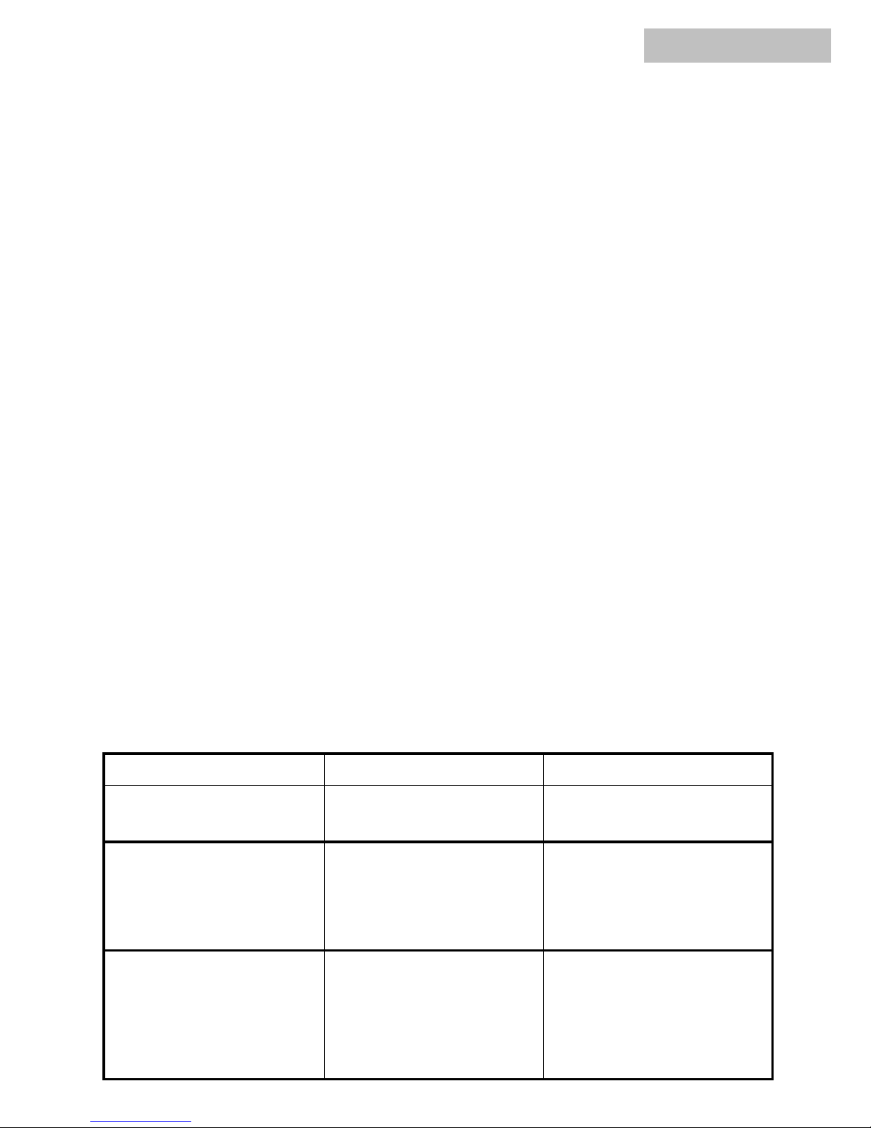
8. Erkennen und Beheben von Fehlern
Problem Mögliche
Ursache
Lösung
Die Pumpe schaltet sich dauernd ein
und aus (Pumpe taktet).
Die Anlage weist Leckagen auf.
Internes Rückschlagventil ist ggf.
undicht.
Die verschiedenen
hydraulischen Ver indungen
ü erprüfen.
Siehe Punkt „6. Wartung“
Die Pumpe setzt sich nicht mehr in
Betrieb.
1. Keine Netzspannung vorhanden.
2. Zu großer Höhenunterschied
zwischen dem Gerät und einem der
A nehmer (Hähne).
3. Die Pumpe ist defekt.
4. Betrie sstörung des Gerätes.
1.Die Elektroanschlüsse
ü erprüfen.
2.Höhenunterschied
Verringern
3. Sich an einen
Fachtechniker wenden.
4. Sich an den Händler
wenden.
Die Pumpe hält nicht an.
1. Die Anlage weist größere Leckagen
auf.
2. Betrie sstörung des Gerätes
3. Internes Rückschlagventil ist
verschmutzt
1. Die Anlage ü erprüfen.
2. Sich an den Händler
wenden
3. Pumpe+Gerät spülen Siehe
Punkt „6. Wartung“
DEUTSCH
3

Contents
1. Preface 5
2. Universal 5
3. Installation 5
4. Operation instructions 5
5. Safety regulations 6
6. Servicing 6
7. Guarantee regulations 6
8. Recognising and repairing of mistakes 6
9. Technical data 7
10. Electric Installation 7
Impressum
1A Profi Handels Gm H
www..profi-pumpe.de
Email: [email protected]
Tel.: (+49) 0611-945877600
Fax: (+49) 0611-9458776911
ENGLISH
4

1. Preface
We would like to congratulate you on the purchase of our pressure switch. We appreciate your trust. That's why functional
security and
perational safety stands y us on first place.
2. Universal
Flow guard is designed to automatize the starting and stopping operations of an electric pump with regard to a drop in pressure
(open Ing of the taps) and to the stopping of the flow through the system (closing of the taps) respectively. Furthermore, Flow
guard stops the pump when senses the lack of waterftow, preventing it from any damaging dry operation.
lt is advisa le using Flow guard with water systems whose water is without sediments. In case it is not possi le, it is necessary
to install a filter efore the inlet of the device.
The pressure gauge indicates the starting pressure value and the pressure in the system.
Furthermore it helps to verifiy any possi le presence of water leakages in the system.
PLEASE READ T IS INSTRUCTION LEAFLET CAREFULLV T ROUG BEFORE INSTALLING AND
PERATING T E DEVICE
3. Installation
•Install Flow guard anywhere etween the pump and the first service outlet. Make sure that device is mounted in
correct flow direction (some devices have the arrows moulded on the case). Check perfect water tightness of all water
connections. If you are using a pump with a pressure higher than 10 Bar,install a pressure reducer on the Flow guard
inlet.
•For the electrical connection of the version supplied without electric leads,follow the wiring diagram on the printed
circuit oard cover, or on the drawing (page 7) following. Furthermore, in case of use of a pump with power higher
than 1/2 HP and the am ient temperature is higher than 25°C it is necessary to wire pressure switch with ca les with a
thermic resistance not inferior to 99 °C. Use only suita le wire nippers to wire the device. If the Ca les are included,
simply connect the pumps power plug to the pressure switch socket and its own power plug to a current outlet.
•Operating pressure is pre-set at 1.5 ar which is the optimum value for the majority of applications. Minimum
operation pressure can e adjusted as needed y turning the screw situated on top of the device, it's marked with+
and-.
•The height of the water column a ove the Flow guard should not e more than 15m.
ATTENTION: The check valve installed in the pump outlet and in the Flow guard inlet can cause some anomalies during the
normal working of Flow guard. Therefore its advisa le avoiding its installation etween the pump and pressure switch
4. Operation Instructions
WARNING: whenever the level of the priming water is lower than the level of the water where the pump is placed, a suction
line equipped with an anti ackflow foot value is a solutely essential. This value allows the line to e filled when it is first used
and prevents it from eing emptied when the pump stops.
•Before first use, fill the pump and the suction pipe with water. Please make sure that all connection are watertight.
•Connecting the electric to the pump (page 7.)
•Open the tap.
•Connecting the pressure switch to power line.
•Wait until water runs out of the tap, than close it.
•After 10-15 sec. the device will switch of the power of the pump.
•Please make sure again that all connection are watertight.
•Installation is correct if the flow from the tap is regular and if the pump works continuously without clocking, and
stop working after reaching the chosen pressure value. Please repeat the test a couple of times.
Dry stop: The red FAILURE LED lights up with motor off to indicate a dry stop. To start the system again press the RESET
utton after having checked the presence of water in the suction pipe .
Attention! Don't install a back-pressure valve between pump and switch!
ENGLISH
5

5. Safety regulations
To avoid shocks and fire risks, read and follow closely the following instructions:
•respect engineer standards and local regulations
•Always unplug the device from the mains efore carrying out any work on it.
•Be sure that the electric line connecting the device to the mains and the extension leads have a cross-section
suita le for pump power and e sure that the electrical connections are far away from any water source.
•When Flow guard is used for wetrooms (pumping water, swimming pools, ponds and fountains..) it is necessary to
use an automatic RCD with
IDn = 3OmA protection.
•Don't use the pump control under steady sunlight.
•Only for use in frost-free conditions (without condensate in the equipment).
Warning: when the pump stops the pipes are under pressure consequently we recommend opening a tap to discharge the system
efore carrying out any work.
6. Servicing
Under normal conditions the pressure switch requires no servicing. It may happens that some dirt uilding up etween
the sealing and it isn't 100% watertight. In this case first try to wash out the device. Open the tap completely and let the
Water flow for a out 30 min. If the Pro lem consists, replace the device, efore installing clean up the pump. Carry on
working with an clocking pump or open the ack-pressure valve leads to an exclusion of statutory guarantee and can e
dangerous.
The following controls should e carried out regularly:
•Intactness of the electric ca le
•That the connection hoses are not ent or roken
•Cleanness of the pump medium
•Moreover, the pump should e emptied with risk of frost, e washed out with clear water and stored dry.
7. Guarantee regulations
For all manufacturer defects and material defects we grant the statutory guarantee time (new and unused product). In
such cases we take over the exchange or the repair of the pump. Forwarding expenses are not carried y us.
The guarantee is not valid with:
•Material wear (sealing rings, impeller wheels, impeller cham ers)
•Unjustified interventions or changes in the pump
•Damages y self fault
•Improper servicing and improper use
•DRY RUN (Also partially!) of the pump
Moreover, we give no damage compensation for secondary damages!
8. Recognising and repairing of mistakes
Problem Possible cause Solution
The pump switches on and off
continuously.
The system is leaking (taps?). Internal
check valve is leaking. Check all hydraulic connections.
The pump is no longer in operation.
1.No connection to mains
power .
2. To ig height difference
etween the device and one of
the cunsumers (taps) .
3. The pump is defective.
4. Malfunction of the device.
1. Check the Electronic connections.
2. Reduce height difference
3. Turn to a professional technician.
4. Contact the dealer.
The pump does not last.
1. The installation has more leaks.
2. Failure of the devices
3 Internal check valve is dirty
1. Check the system.
2. Contact the dealer
3. Rinse pump and device. See
paragraph 6 « Servicing »
ENGLISH
6

9. Technical Data / Technische Daten
English Deutsch PS01109
Tension/Voltage Betrie sspannung 110-230 VAC ± 10% 50/60 Hz
Max. Current Max. Nennstrom 10 A
Max. Power demand Max Anschlussleistung 1,1 kW
Rating pressure Einschaltdruck 1,5 - 3 ar
Max. Operating Pressure Max. Betrie sdruck 10 ar
Max water temperature Max. Wassertemperatur 60°C
Input connector Anschlüsse Eingang 2,54 cm (1“)
Output connector Anschlüsse Ausgang 2,54 cm (1“)
Protection-grade Schutzart IP 65
10. Electric installation / Elektrischer Anschluss-Plan und Installationsschema
7
Technische Änderungen, Druckfehler und Irrtümer vor ehalten!
L1: Power: raun/ rown (Phase)
N: Power: lau/ lue (Null)
E: Power:grün_gel / green_yellow (Erde)
E: Pumpe:grün_gel / green_yellow (Erde)
U: Pumpe: lau/ lue (Null)
V:Pumpe: raun/ rown (Phase)
+ /- Einstell arer Einschaltdruck
Anschluss-Plan
ENGLISH / DEUTSCH
Table of contents
Languages:
Popular Controllers manuals by other brands

LED Technologies, Inc.
LED Technologies, Inc. R208 user manual

D-Box
D-Box G5 quick start guide

Eaton
Eaton xComfort CDAE-01/01 Assembly instructions

Honeywell
Honeywell Ex-Or MSM2000D Installation and commissioning instructions

Honeywell
Honeywell CIPer 50 Installation & commissioning instructions

Blankom
Blankom HCB 100 manual