2Box SpeedLight Kit User manual

SpeedLight Kit
USER’S MANUAL
BEDIENUNGSANLEITUNG

CONTENTS TABLE
INSTALLATION ......................................................................................
1
PLAYING.................................................................................................
9
AUFBAU ...............................................................................................
11
SPIELEN...............................................................................................
19
www.2box-drums.com

!
SERVICE
This product may only be serviced by qualified
service personnel.
HANDLING AND TRANSPORT
Never apply excessive force to connectors,
pads or other parts of the instrument.
Always unplug cables by gripping the plug
firmly, not by pulling on the cable.
Physical shocks caused by dropping,
bumping or placing heavy objects on the
instrument can result in scratches and/or
more serious damage.
LOCATION
Do not expose the drum set to the following
conditions to avoid deformation, discoloration
or more serious damage:
direct sunlight (near a window),
high temperatures (near a heat source,
outside or in a car during the daytime),
excessive humidity,
excessive dust,
strong vibration.
CLEANING
Clean the unit with a dry or damp soft cloth.
Do not use paint thinner or petrochemical-based
polishes.
TAKING CARE OF YOUR DRUM
INSTALLATION
CRASH
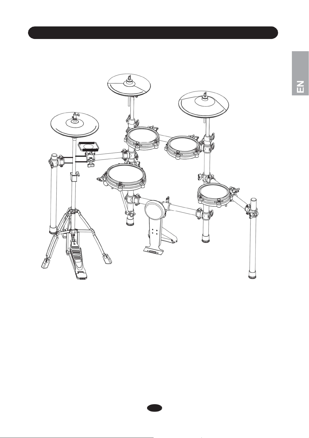
The diagram shows the complete drum kit after installation.
RIDE
HI-HAT
SOUND
MODULE
HOLDER
TOM1
TOM2
SNARE
TOM3
KICK
1
INSTALLATION
4a
RACK INSTALLATION - 1
①
② ③
④
⑥
⑦
⑩
⑨
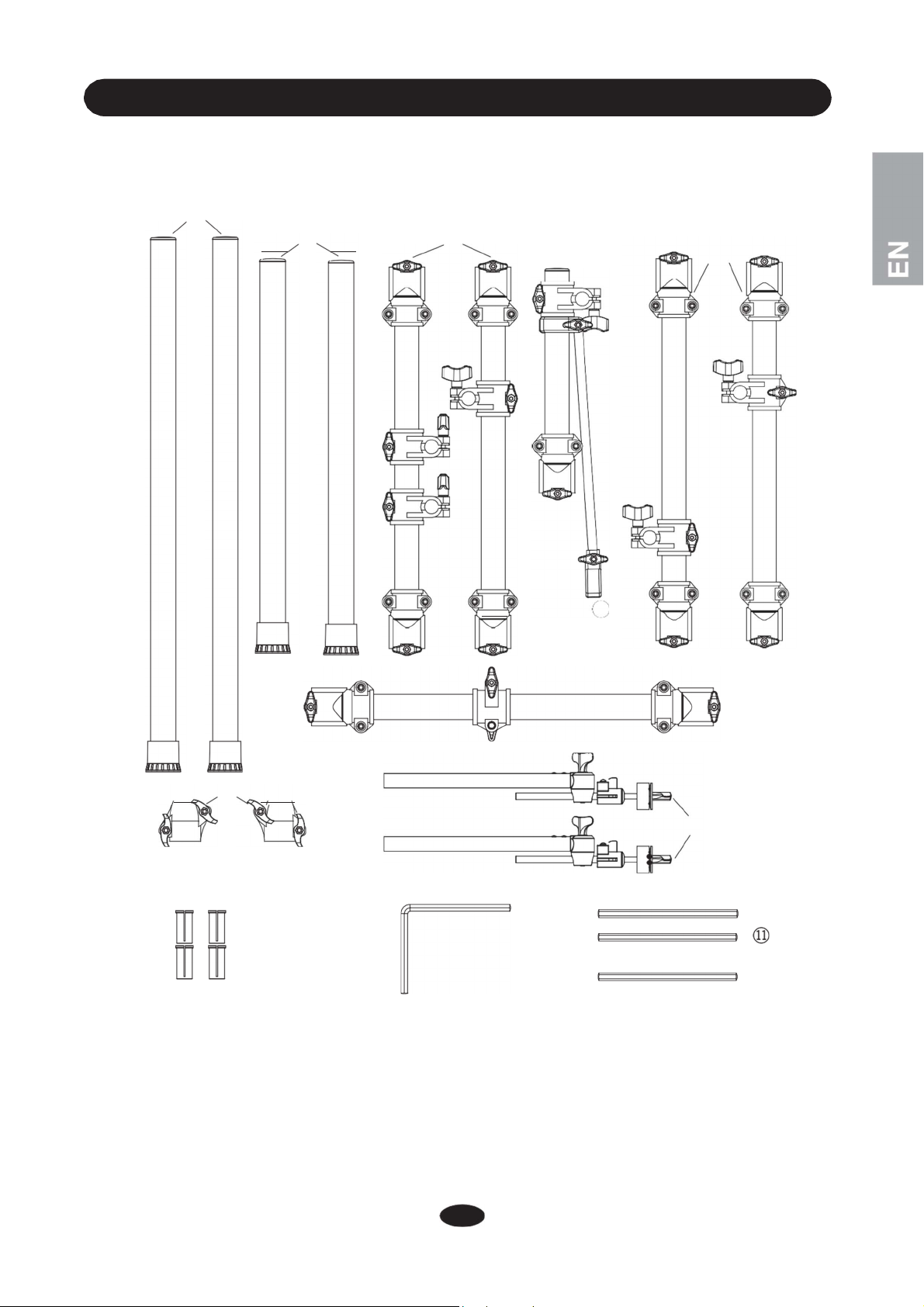
This is the view of the individual parts. Set up the drums according to the diagram on the next pages.
2
⑧
⑤

INSTALLATION
RACK INSTALLATION - 2
3
WARNING: Fasten related wing nuts after
each step to avoid that components fall.
1. Insert post (1) into cross bar (6) as shown
in the picture. Fasten its wing nuts.
2. Turn the side without wing nuts towards
you. Insert bar (4) into the left center
post (1L).
3. Take off the rubber foot on left center
post (1L) and move down bar (4) so the
snare bracing rod (4a) can be fitted into
the bottom of left center post (1L).
④
⑥
①
①
4a

INSTALLATION
RACK INSTALLATION - 3
4
4. Move both bar (4) and snare bracing rod
(4a) up at the same time. Then fit the loop to
the left center post (1L). Fasten the wing
nuts.
5. Insert cross bar (5) into the left center post
(1L). Fasten its wing nut. Insert side post (2)
into the other side.
6. Insert cross bar (5) into right center post
(1R). Fasten its wing nut. Insert side post
(2)
into the other side.
7.
Insert cross bar (3) into both center posts (1)
and fasten its wing nuts.
③
⑤
④
⑤
②
①
①
4a
②
INSTALLATION
RACK INSTALLATION - 4
5
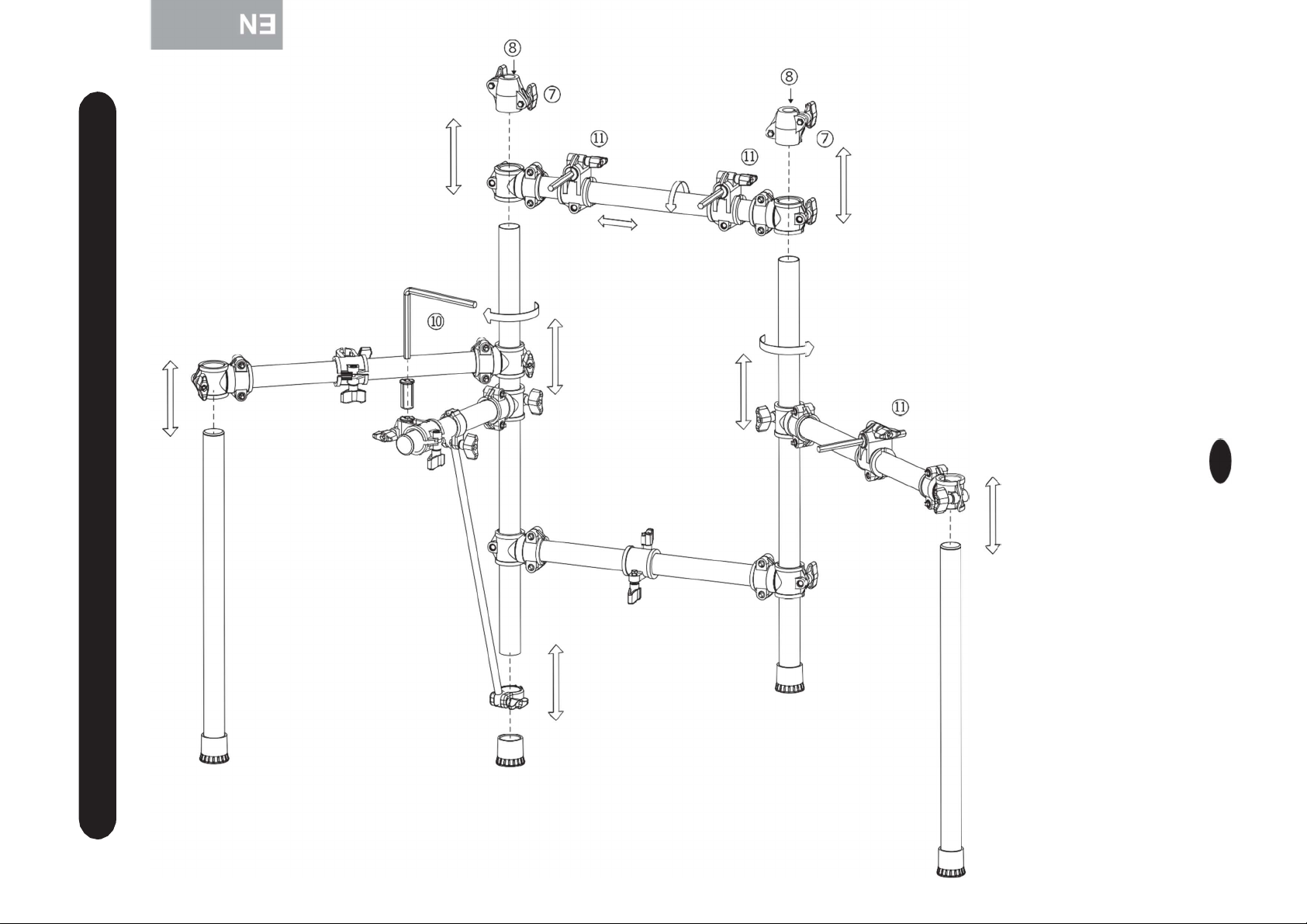
8.
Insert both cymbal rod connector clamps (7)
into the top of center posts.
Insert cymbal rod (8) into cymbal rod
connector clamps (7).
⑨
⑨
9.
10. Insert hex rod sleeves (9) into their
clamps as shown in the picture.
11. Insert the L-shaped hex rod (10) into
a hex rod sleeve (9) as shown in the
picture.
12. Insert the other hex rods (11) into the
hex rod sleeves (9).
⑨
⑨
④
⑤
⑨

INSTALLATION
RACK INSTALLATION - 5
6
⑧
⑧
⑨
⑨
⑦
⑦
③
⑨
⑤
④
⑤
⑨
⑩
⑥
①
①
②
4a
This diagram shows the completely
installed drum rack. Please check the
rack before you start pad installation.
②
INSTALLATION
COMPONENTS INSTALLATION - 1
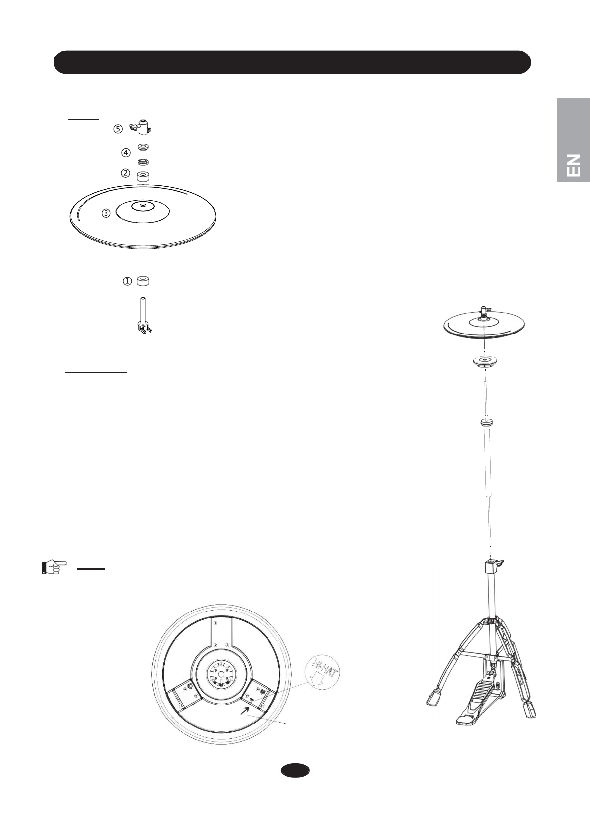
Hi-Hat
1. Slide the large felt (1) onto the hollow rod.
2.Slide one of the two small felts onto the threaded
rod of the Hi-Hat clutch.
3. Insert the threaded rod from below through the
Hi-Hat pad (3). Pay attention to the guide groove.
4. Slide the second small felt onto the threaded rod
and fix the Hi-Hat clutch with both nuts (4) as
shown in the illustration. Please don’t tighten the
nuts too much.
5. Now screw the head (5) onto the Hi-Hat clutch
and fix it with the square nut.
Hi-Hat Stand
1. Open the Hi-Hat stand legs (1) to a suitable position so that they stand firm.
2. Insert thin rod (2) into the screw thread on the bottom stand according to
dashed line and rotate it clockwise to fasten it.
3. Place the hollow rod (3) outside the rod (2) and insert it into the bottom stand.
4.Insert the Hi-Hat pad tray (4) onto the thin rod (2) and place it above the
hollow rod (3).
5. Adjust the hollow rod (3) to a suitable height and fasten it. Insert the
Hi-Hat pad (5) onto the thin rod (2). Make sure there is enough space
between the pad and tray (4) and then fasten the screw holding the pad.
6. Important: Make sure that the trigger zone (semicircle) of the Hi-Hat pad is
directed towards you.
Note: If there is not enough space between the pad and the tray (4), the
Hi-Hat pad will not react properly not respond at all.
PLUG THE CABLE HERE
7
②
①
④
⑤
③
Table of contents
Languages:
Other 2Box Drum manuals


