7
2 VV. Creating innovative solutions for you and your business since 1995.
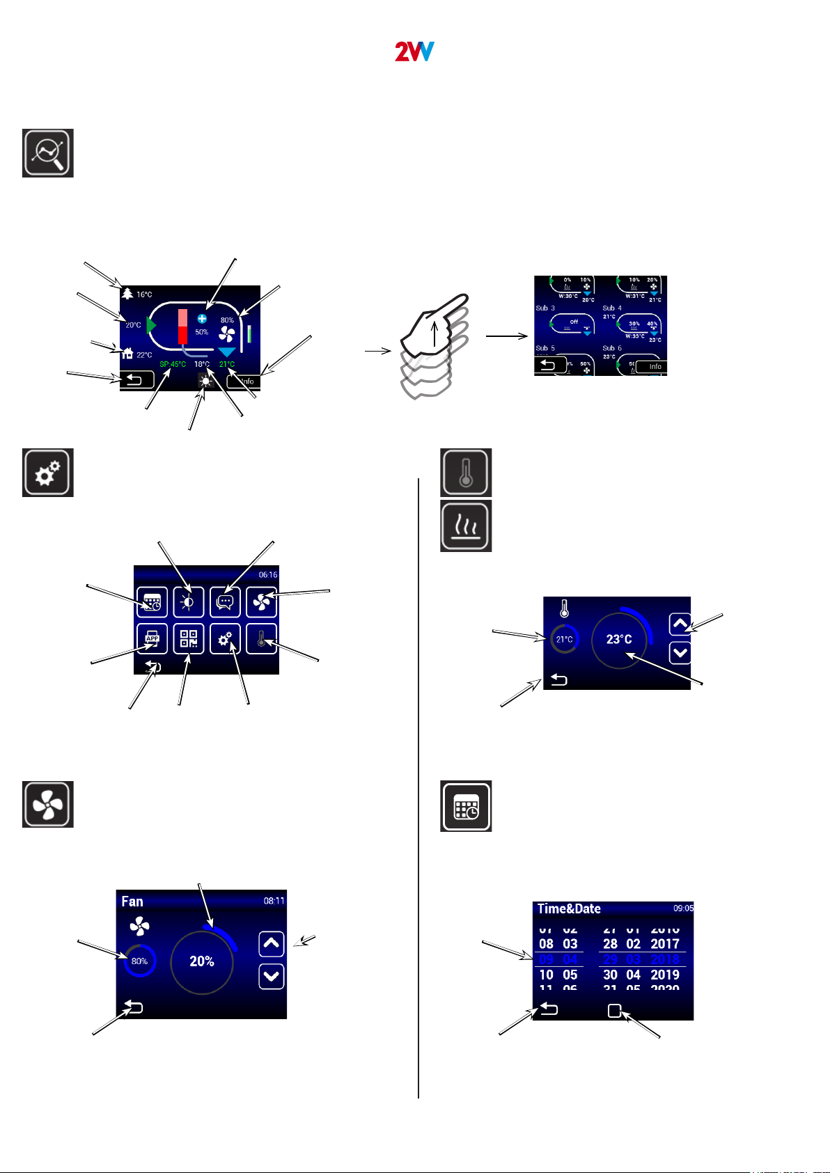
RESET button
(use after replacing
lters)
MENU - OUTLET TEMP LIMITS
MENU - MODBUS RTU
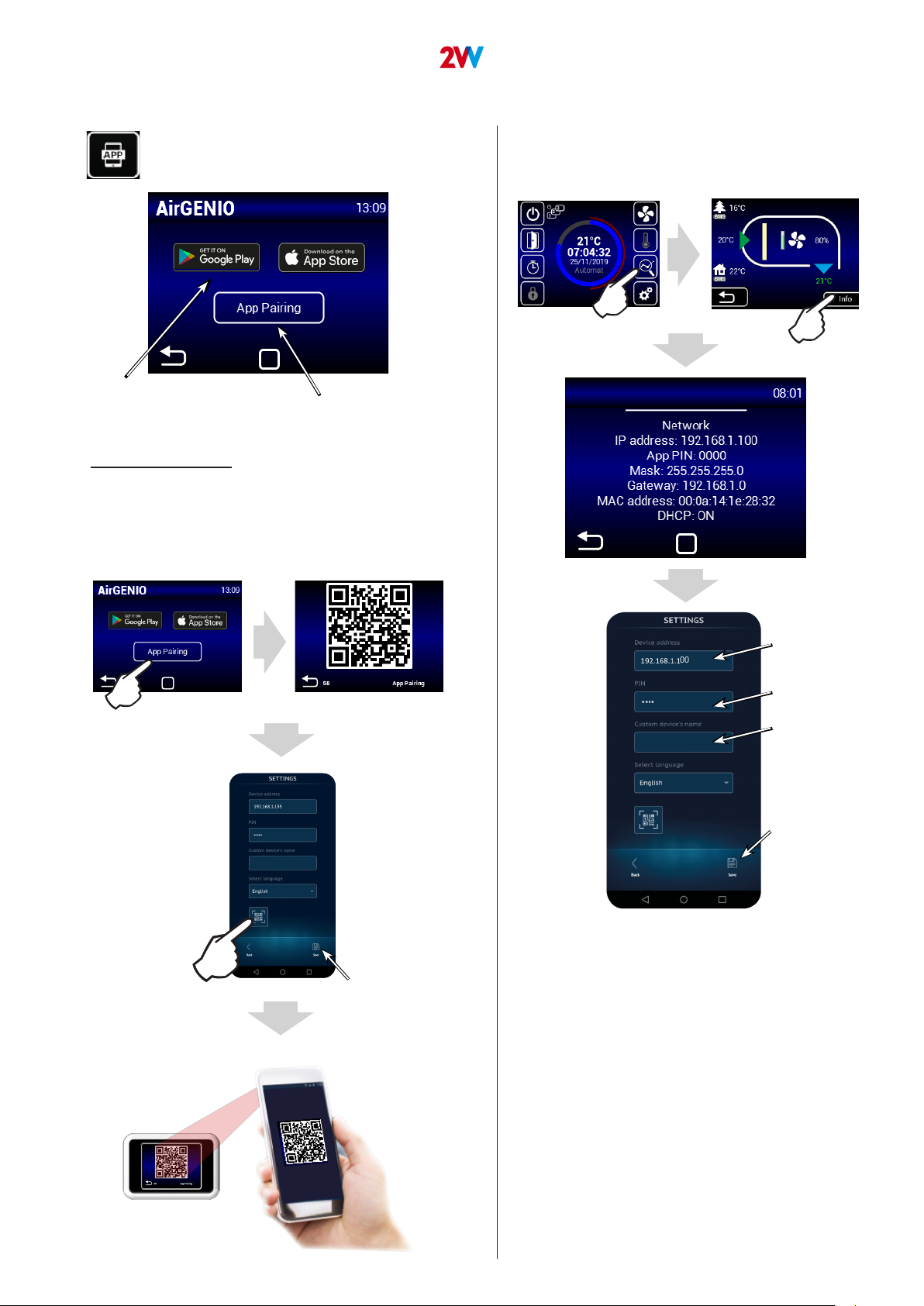
MENU - NETWORK
Maximum temperature limit: 25°C - 45°C
Address
1~247
Parity
None
Odd
Even
DHCP blocked/enabled
Regulator network settings to
be entered manually:
IP address
Mask
Gate
Communication speed:
4800 Bd
9600 Bd
14400 Bd
19200 Bd
38400 Bd
Minimum temperature limit: 15°C - 20°C
Use this menu to set the limits of the exhaust
Use this menu to set the Modbus RTU communication
parameters
Use this menu to set the communication parameters of
the network interface
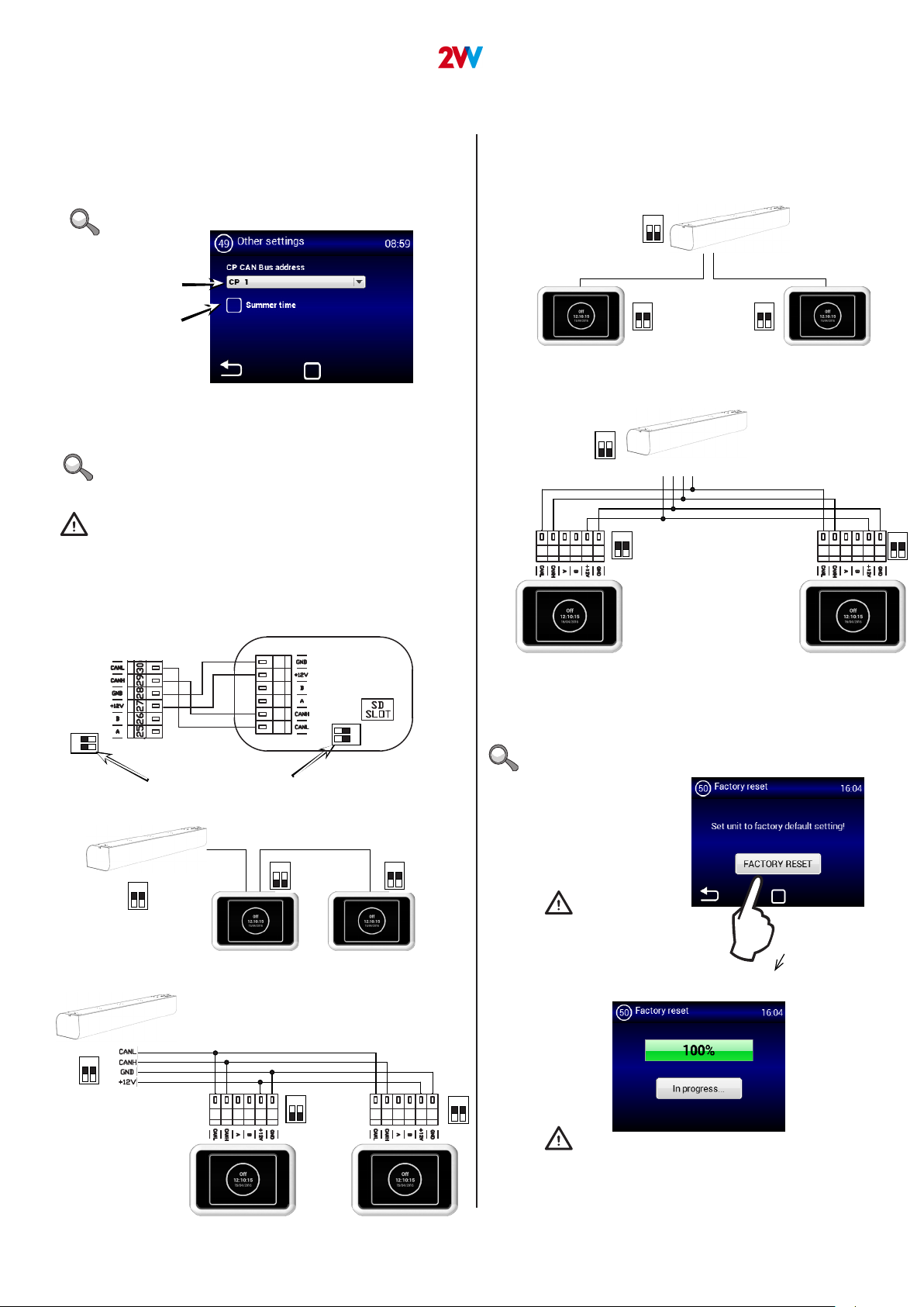
An incorrect setting may prevent communication with
the regulator
An incorrect setting may prevent communication with the
regulator
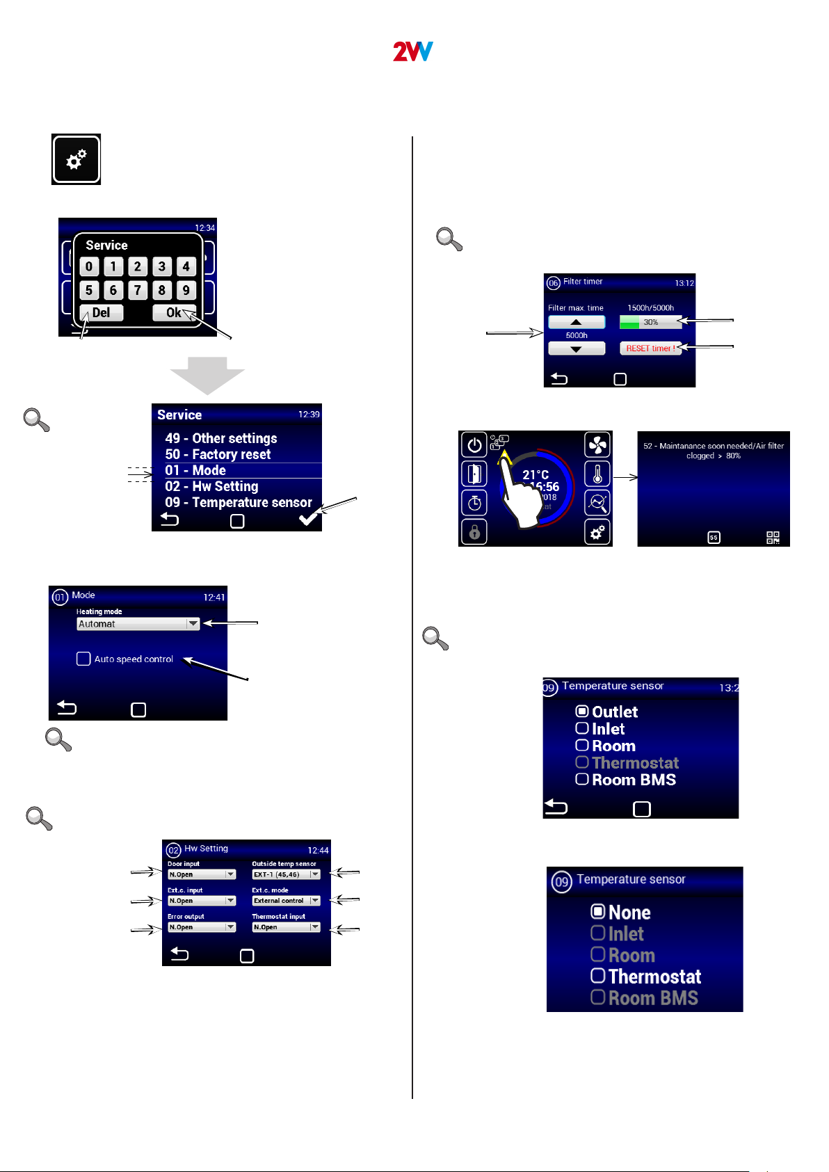
If “OUTLET” is selected in the TEMPERATURE SENSOR
MENU, it will not be possible to set values as they are
already dened by the sensor. You will see this screen:
1. CONTROL
MENU - USER LOCK
MENU - SUMMER HEATING
Limit level – see Ad1)
Enter PIN 0000~9999
(numeric values only)
Use this menu to set the limits to control the regulator
with a multi-level panel
Use this menu to set heating limits in summer months
If the outside temperature sensor is not set,
the “summer heating” mode will operate only according
to the selected time and the temperature will not be taken
into account
Options:
None – Limit inactive
On/O – Only On/O and access to the information menu are
enabled in the main screen
On/O, Temp, Flow – On/O, the information menu, and temperature and air ow
settings can be accessed without password.
Full – Only the information menu can be accessed without password
User mode – Special user mode, see image below
End of winter period
(month number)
Start of winter
period (month number)
Enable/disable
function
Temperature limit – the
heating is disabled if the
temperature on the “Outdoor”
sensor is higher than the one
set here
MENU - Night Reduction
This MENU allows for setting reduced temperatures dur-
ing night hours with closed doors.
In this menu, the reduction of temperature may be set
only by ve degrees at the set time compared to the
set (required) temperature.
Setting reduced
temperature range -1~-5°C
Setting start time
for reduced
temperature
Setting time for ending
reduced temperature.
Activating function