Salus VS05 User manual

Dial Thermostat
Models: VS05
INSTALLER / USER MANUAL
iT600 VS05 Installer - User Manual 005_Layout 1 08.12.2014 13:32 Strona 1

02 VS05 Installer Manual
Contents
1 x Installer / User manual VS05Fixing screws
Contents
Introduction.
Product Compliance.
Safety information.
Mounting position and
installation.
System grouping and
communication.
User interface.
LED indication.
Box Contents
Icons used in this manual:
Safety
Important info
Your benet
For latest PDF installation
guide please go to
www.salus-controls.com
iT600 VS05 Installer - User Manual 005_Layout 1 08.12.2014 13:32 Strona 2

Product Compliance & Safety Information
We hope you enjoy this product...
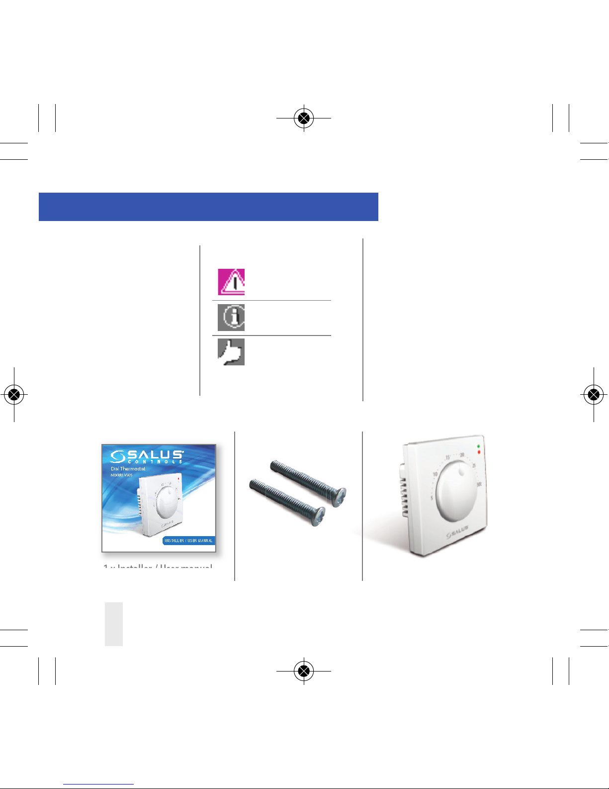
VS05 Installer Manual 03
INTRODUCTION
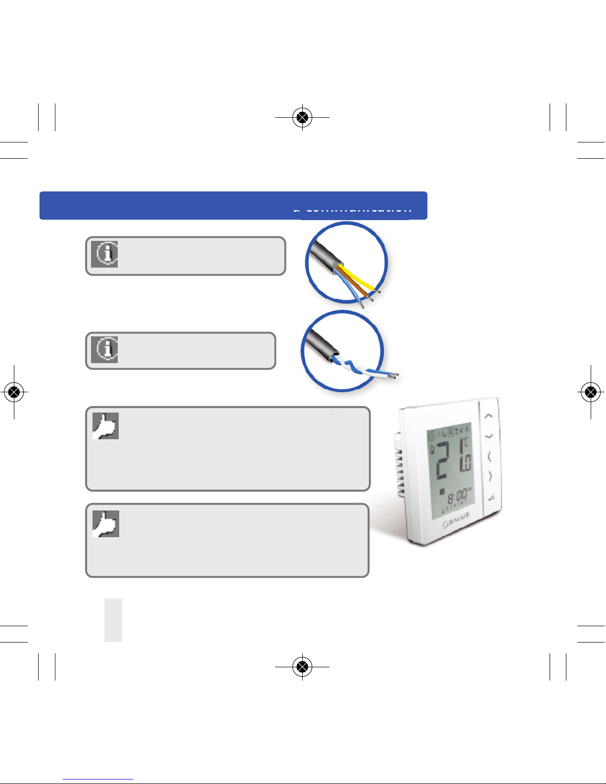
Thank you for purchasing the SALUS room
thermostatVS05. TheVS05 is a 230V dial
thermostat which oers simple temperature
control of your heating system.
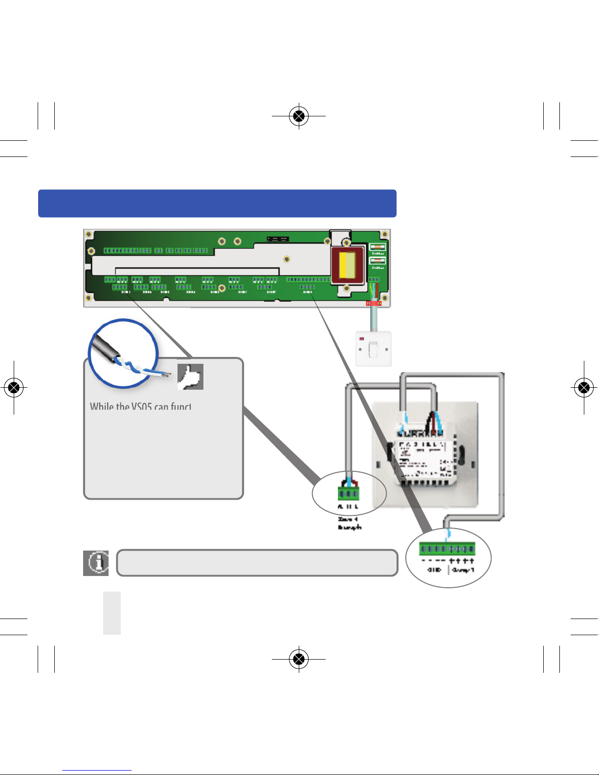
SALUS recommends that you use your VS05
with the SALUS KL10 wiring centre and VS10
digital room thermostat.TheVS10 can be used
as a group control thermostat to control groups
of VS05’s. Please see pages 6 and 7.
Product Compliance
This product is CE compliant and meets the
following EC Directives Electro-Magnetic
Compatibility directive 2004/108/EC
Low voltage Directive 2006/95/EC
Safety Information
Use in accordance with the regulations
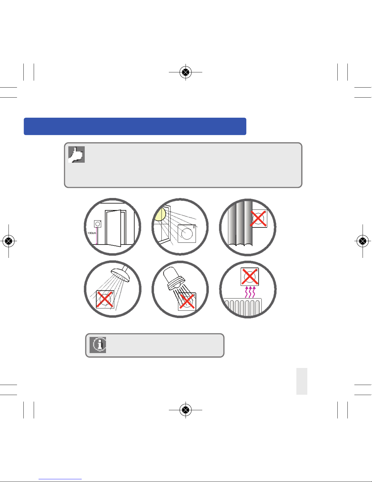
The SALUSVS05 is to be used for room
control of hot water heating systems
inside the house.
Installation
This product must be tted by a competent
person, and installation must comply with the
guidance, standards and regulations applicable
to the city, country or state where the product
is installed. Failure to comply with the
requirements of the relevant guidance,
standards and regulations could lead to injury,
death or prosecution.
Always isolate the AC mains supply
before installing or working on any components
that require 230V AC 50Hz supply.
iT600 VS05 Installer - User Manual 005_Layout 1 08.12.2014 13:32 Strona 3

Product Compliance & Safety Information
Sources of danger
The thermostat must be disconnected from
mains supply before removing the cover.
230V AC
Emergency
Switch o the voltage to the individual
thermostat wiring centre or complete system.
Installer parameter settings
The SALUSVS05 is equipped
with installer parameters. See page 13.
For the installer
Please enter any parameter
changes in the installer notes section.
04 VS05 Installer Manual
iT600 VS05 Installer - User Manual 005_Layout 1 08.12.2014 13:32 Strona 4

VS05 Installer Manual 05
Installation –Thermostat Mounting
Not to be positioned on an exterior wall.
Mounting position and installation
To ensure trouble free operation and ecient control, the unit is best positioned in
a draft free area and at 130cm from the oor. Do not position the thermostat near
any heat source, behind curtains, direct sunlight or an area of high humidity.
iT600 VS05 Installer - User Manual 005_Layout 1 08.12.2014 13:32 Strona 5

06 VS05 Installer Manual
System Overview Grouping and Communication
Power and Switching Cable - used to
power thermostats and drive output.
Grouping and Communication cable.
While the thermostats can function as standalone,
installing this optional inexpensive communication cable
allows the thermostats to communicate with the SALUS
VS10 congured as a group control thermostat and used
with the SALUS KL10 WC (both sold separately).
The VS05 will follow instructions from the VS10 bringing
central control of features such asTime Control, Holiday &
Party functions as well as Frost Control.TheVS05 can leave
or re-enter group control at the slide of a switch. VS10 Group ControlThermostat
(sold separately )
iT600 VS05 Installer - User Manual 005_Layout 1 08.12.2014 13:32 Strona 6

Group 2 – For Example upstairs
VS05 Installer Manual 07
System Overview Grouping and Communication
The maximum number of groups per KL10 wiring centre is two. The group selection
communication cable must correspond to the group terminals on the KL10WC.
Please refer to note 5 and the KL10 installation guide.
Group 1 – For Example Down stairs
SALUS KL10 Wiring Centre
iT600 VS05 Installer - User Manual 005_Layout 1 08.12.2014 13:32 Strona 7

08 VS05 Installer Manual
Installation –Thermostat Mounting
1
3
2
60mm
Wall Mounting
For wall mounting, mark and mount
the rear case to the wall.TheVS05 is
suitable for wall boxes with a centre
hole distance of:
Gently remove front housing.
iT600 VS05 Installer - User Manual 005_Layout 1 08.12.2014 13:32 Strona 8

VS05 Installer Manual 09
Installation –Terminal Connections
Understanding your terminal connections
Rear of VS05
Power Terminals 230 Vac
Used for supplying power to the
unit and switched output.
Sensor Terminals
Can be used for external Air or
Floor sensor.
Communication Terms 12VDC
Two wire twisted pair
can be used for grouping
functions between VS10 and VS05.
Also required for Heat/Cool
changeover.
3
1
2
3 2 1
iT600 VS05 Installer - User Manual 005_Layout 1 08.12.2014 13:32 Strona 9

10 VS05 Installer Manual
Installation –Thermostat Connections
While theVS05 can function on
its own, installing this optional,
inexpensive communication
cable allows theVS05 to
communicate with the SALUS
VS10 (sold separately).
Optional
communication
connection 12VDC
For more detail refer to note 5 on the wiring centre installation guide.
iT600 VS05 Installer - User Manual 005_Layout 1 08.12.2014 13:32 Strona 10

VS05 Installer Manual 11
Installation –Terminal Connections
Power Terminals
Sensor Terminals (if applicable)
Communication Terminals (optional but recommended)
You are ready to secure the rear housing to the wall box
Check that the wiring is completed for:
1
2
3
Please use the screws provided.
Ensure the orientation arrow
is pointing upwards.
iT600 VS05 Installer - User Manual 005_Layout 1 08.12.2014 13:32 Strona 11

Installation
12 VS05 Installer Manual
1
2
4
3
If any parameter settings need
to be changed please refer to next page. Fit the front housing to the rear
housing as shown above.
12
iT600 VS05 Installer - User Manual 005_Layout 1 08.12.2014 13:32 Strona 12

Installation – parameter setting
VS05 Installer Manual 13
FUNCTION DESCRIPTION DEFAULT
Valve Exercising
PWM
External sensor
type
Actuator type
Reduced temp
oset / Night
setback
ENABLE
ON
AIR
NC
4ºC
If the installer setting is to enable the valve exercising the
dial thermostat will additionally send 5 minute pulse on
actuator once a week.
PWM output to drive actuator open/close.
Air or oor.
Normally Closed or Normally Open.
0, 4, 6 or 8 (only when used withVS10 and KL10).
12
2
External sensor (optional)
If you are tting an external sensor for air/oor
sensing please select temp here. It can be set
from 0-45ºC and is preset at 27ºC. Please note
the dip switches need to be set for the
correct external sensor type, see below.
iT600 VS05 Installer - User Manual 005_Layout 1 08.12.2014 13:32 Strona 13

User Interface
14 VS05 Installer Manual
LED Indication
Temperature Adjustment 5-30 oC
Mode
Selection
The VS05 is a group member and will follow commands
from theVS10 group control thermostat.
The VS05 is no longer a member of the group and will
ignore commands from theVS10 group control thermostat.
TheVS10 is switched o, frost protection of 5ºC is active.
iT600 VS05 Installer - User Manual 005_Layout 1 08.12.2014 13:32 Strona 14

LED Indication - Group Member
VS05 Installer Manual 15
Slide switch must be in position to follow group control thermostat VS10, see page 14.
If you do not want a VS05 to follow the group control thermostat VS10
please select or see previous page.
RED LED indicates that power is going to the
thermostat in normal operation. The top LED
will illuminate when room temperature falls
below your required temperature.
Green LED means that the thermostat
is calling for heat. The group control
thermostat will be in one of the
following modes:
1.
2.
3.
VS10 group control
thermostat display
For more details on VS10
please refer to VS10 manual
iT600 VS05 Installer - User Manual 005_Layout 1 08.12.2014 13:32 Strona 15

16 VS05 Installer Manual
LED Indication - Group Member
To reduce annoyance factor, no LED is shown
when the group control thermostat is in
reduced temperature/night setback mode.
See below.
To adjust reduced temperature
oset please refer to page 13.
Amber LED means that the
thermostat is calling for heat in
reduced/night setback mode.
The group control thermostat will
be in one of the following modes:
1.
2.
VS10 group control
thermostat display
For more details on VS10
please refer to VS10 manual
Slide switch must be in position to follow group control thermostat VS10, see page 14.
If you do not want a VS05 to follow the group control thermostat VS10
please select or see page 14.
iT600 VS05 Installer - User Manual 005_Layout 1 08.12.2014 13:32 Strona 16

VS05 Installer Manual 17
LED Indication - Group Member
Blue LED indicates the thermostat is in
frost protection mode. Frost protection
temperature is xed at 5ºC.
Green LED means that the
temperature has fallen below the
frost protection level the thermostat
is calling for heat. The group control
thermostat will be in one of the
following modes:
1.
2.
VS10 group control
thermostat display
For more details on VS10
please refer to VS10 manual
Slide switch must be in position to follow group control thermostat VS10, see page 14.
If you do not want a VS05 to follow the group control thermostat VS10
please select or see page 14.
iT600 VS05 Installer - User Manual 005_Layout 1 08.12.2014 13:32 Strona 17

LED Indication - Manual mode
18 VS05 Installer Manual
To enter manual mode, slide the switch to the position. The thermostat will not follow the group
control thermostat VS10 and will no longer be part of the group.The VS05 will work as a stand alone thermostat.
To return theVS05 to the group (if applicable) move the slide switch to
RED Led indicates that power is
going to the unit in normal
operation. The top LED will
illuminate when room
temperature falls below your
required temp.
Green LED means that
the unit is calling for heat.
iT600 VS05 Installer - User Manual 005_Layout 1 08.12.2014 13:32 Strona 18

LED Indication -Permanent Frost Mode
VS05 Installer Manual 19
To enter manual mode, slide the switch to the position. The thermostat will not follow the group control
thermostatVS10 and will no longer be part of the group. TheVS05 will be in permanent frost protection.
Blue LED indicates the
thermostat is in frost protection
mode. Frost protection
temperature is xed at 5ºC.
Green LED indicates the
temperature has fallen below the
frost protection level and the
thermostat is calling for heat.
To return theVS05 to the group (if applicable) move the slide switch to
iT600 VS05 Installer - User Manual 005_Layout 1 08.12.2014 13:32 Strona 19

Technical Detail
20 VS05 Installer Manual
MODEL
TYPE
TEMPERATURE
Scale
Tolerance
Set Temperature range
Frost Protection
CONTROL
ENVIRONMENT RATINGS
Operating Temperature
Storage Temperature
Operating Humidity
(non condensed)
POWER SOURCE
CONTROL SWITCH AND RATING
Loading
Input
AGENCY APPROVED
VS05
Wired dial thermostat designed for 230V AC
heating/cooling applications
Celsius
0.5 ºC
5-30 ºC
5ºC
ON-OFF control / PWM control
0ºC to +50 ºC
-20ºC to +60 ºC
5-95 %RH
230Vac 50Hz
Maximum 3A at SL terminal
Comm Connection 12VDC
CE
iT600 VS05 Installer - User Manual 005_Layout 1 08.12.2014 13:32 Strona 20
Other manuals for VS05
1
Table of contents
Other Salus Thermostat manuals

Salus
Salus RT 10 User manual

Salus
Salus BTRP230V User manual

Salus
Salus ST320 User manual

Salus
Salus RT510BC User manual

Salus
Salus RT510 User manual

Salus
Salus RT310i User manual

Salus
Salus RT510RF Service manual

Salus
Salus Quantum WQ610 User manual

Salus
Salus 091FLRF User manual

Salus
Salus ERT20RF User manual
Popular Thermostat manuals by other brands

Tekmar
Tekmar 519 user manual

Vimar
Vimar SMART HOME VIEW WIRELESS 02973 instructions

Jackson Systems
Jackson Systems Web Comfort Z-2000 Quick installation and start-up guide

Esic
Esic HTC625E installation instructions

Theben
Theben RAMSES 831 top operating instructions

Theben
Theben RAMSES 784 Operating instruction