manuals.online logo
Brands
  1. Home
  2. •
  3. Brands
  4. •
  5. dixell
  6. •
  7. Thermostat
  8. •
  9. dixell WING XW40LS Wiring diagram

dixell WING XW40LS Wiring diagram

dIXEL
Installing and Operating Instructions rel.1.0 - cod. 1598002153
1598002153 XW40LS GB VCS r1.0 06.12.2006.doc XW40LS 1/3
WING
XW40LS
1. GENERAL WARNING
1.1 PLEASE READ BEFORE USING THIS MANUAL
•This manual is part of the product and should be kept near the instrument for easy and quick
reference.
•The instrument shall not be used for purposes different from those described hereunder. It cannot
be used as a safety device.
•Check the application limits before proceeding.
1.2 SAFETY PRECAUTIONS
•Check the supply voltage is correct before connecting the instrument.
•Do not expose to water or moisture: use the controller only within the operating limits avoiding
sudden temperature changes with high atmospheric humidity to prevent formation of
condensation
•Warning: disconnect all electrical connections before any kind of maintenance.
•Fit the probe where it is not accessible by the End User. The instrument must not be opened.
•In case of failure or faulty operation send the instrument back to the distributor or to “Dixell S.p.A.
(see address) with a detailed description of the fault.
•Consider the maximum current which can be applied to each relay (see Technical Data).
•Ensure that the wires for probes, loads and the power supply are separated and far enough from
each other, without crossing or intertwining.
•In case of applications in industrial environments, the use of mains filters (our mod. FT1) in
parallel with inductive loads could be useful.
2. GENERAL DESCRIPTION
Model XW40LS, 38x185 mm format, is microprocessor based controller suitable for applications on
medium or normal temperature refrigerating units. It is provided with 3 relay outputs to control
compressor , light and fan.
It is also provided with 1 NTC or PTC probe inputs for temperature control.
An output allows the user to programme the parameter list with the “Hot Key”.
3. CONTROLLING LOADS
3.1 THE COMPRESSOR
The regulation is performed according to the temperature measured by the thermostat probe with a
positive differential from the set point: if the temperature increases and reaches set point plus
differential the compressor is started and then turned off when the temperature reaches the set point
value again.
In case of fault in the thermostat probe the start and stop of the compressor are timed through
parameters “COn” and “COF”.
3.2 FAST FREEZING
When defrost is not in progress, it can be activated the keypad by holding the okey pressed for about
3 seconds. The compressor operates in continuous mode for the time set through the “CCt” parameter.
The cycle can be terminated before the end of the set time using the same activation key, ofor about
3 seconds.
3.3 DEFROST
The defrost interval is control by means of parameter “EdF”: (EdF=in) the defrost is made every “IdF”
time, (EdF=Sd) the interval “IdF” is calculate through Smart Defrost algorithm (only when the
compressor is ON).
Defrost is performed through a simple stop of the compressor. Parameter “IdF” controls the interval
between defrost cycles, while its length is controlled by parameter “MdF”.
4. KEYBOARD
FF
FC
To display and modify target set point; in programming mode it selects a parameter or
confirm an operation.
By holding it pressed for 3s when max or min temperature is displayed it will be erased.
To see the max. stored temperature; in programming mode it browses the parameter
codes or increases the displayed value. By holding it pressed for 3s the fast freezing cycle
is started.
To see the min stored temperature; in programming mode it browses the parameter codes
or decreases the displayed value.
By holding it pressed for 3s the defrost is started.
Switch ON and OFF the light of the cold-room
Switch ON and OFF the instrument.
KEY COMBINATIONS
+
To lock and unlock the keyboard.
+
To enter the programming mode.
+
To exit the programming mode.
4.1 USE OF LEDS
Each LED function is described in the following table.
LED MODE Function
ON The compressor is running
FLASHING - Programming Phase (flashing with LED )
- Anti-short cycle delay enabled
FLASHING Programming Phase (flashing with LED )
ON The defrost is enabled
FLASHING Drip time in progress
ON The Fast Freezing cycle is enabled
ON - ALARM signal
- In “Pr2” indicates that the parameter is also present in “Pr1”
ON The light is on
4.2 HOW TO SEE THE MIN TEMPERATURE
1. Press and release the nkey.
2. The “Lo” message will be displayed followed by the minimum temperature recorded.
3. By pressing the nkey or waiting for 5s the normal display will be restored.
4.3 HOW TO SEE THE MAX TEMPERATURE
1. Press and release the okey.
2. The “Hi” message will be displayed followed by the maximum temperature recorded.
3. By pressing the okey or waiting for 5s the normal display will be restored.
4.4 HOW TO RESET THE MAX AND MIN TEMPERATURE RECORDED
To reset the stored temperature, when max or min temperature is displayed :
1. Press SET key until “rST” label starts blinking.
N.B. After the installation RESET the temperature stored .
4.5 HOW TO SEE AND MODIFY THE SET POINT
1. Push and immediately release the SET key: the display will show the Set point value;
2. The SET LED start blinking;
3. To change the Set value push the o or narrows within 10s.
4. To memorise the new set point value push the SET key again or wait 10s.
4.6 TO START A MANUAL DEFROST
1. Push the DEF key for more than 2 seconds and a manual defrost will start.
4.7 TO ENTER IN PARAMETERS LIST “PR1”
To enter the parameter list “Pr1” (user accessible parameters) operate as follows:
+
1. Enter the Programming mode by pressing the Set and DOWN key for few
seconds ( and start blinking).
2. The instrument will show the first parameter present in “Pr1”
4.8 TO ENTER IN PARAMETERS LIST “PR2”
To access parameters in “Pr2”:
1. Enter the “Pr1” level.
2. Select “Pr2” parameter and press the “SET” key.
3. The “PAS” flashing message is displayed, shortly followed by “0 - -” with a flashing zero.
4. Use oor nto input the security code in the flashing digit; confirm the figure by pressing “SET”.
The security code is “321“.
5. If the security code is correct the access to “Pr2” is enabled by pressing “SET” on the last digit.
Another possibility is the following: after switching ON the instrument the user can push Set and DOWN
keys within 30 seconds.
NOTE: each parameter in “Pr2” can be removed or put into “Pr1” (user level) by pressing “SET” + n.
When a parameter is present in “Pr1” LED is on.
dIXEL
Installing and Operating Instructions rel.1.0 - cod. 1598002153
1598002153 XW40LS GB VCS r1.0 06.12.2006.doc XW40LS 2/3
4.9 HOW TO CHANGE THE PARAMETER VALUE
1. Enter the Programming mode.
2. Select the required parameter with oor n.
3. Press the “SET” key to display its value ( and LED starts blinking).
4. Use oor nto change its value.
5. Press “SET” to store the new value and move to the following parameter.
To exit: Press SET + UP or wait 15s without pressing a key.
NOTE: the new programming is stored even when the procedure is exited by waiting the time-out.
4.10 HOW TO LOCK THE KEYBOARD
+
1. Keep the oand nkeys pressed together for more than 3 s the oand nkeys.
2. The “POF” message will be displayed and the keyboard is locked. At this point it is
only possible the viewing of the set point or the MAX o Min temperature stored and
to switch ON and OFF the light, the auxiliary output and the instrument.
TO UNLOCK THE KEYBOARD
Keep the oand nkeys pressed together for more than 3s.
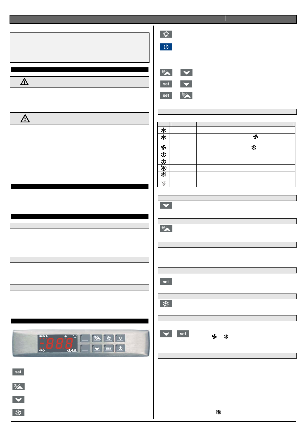
4.11 ON/OFF FUNCTION
By pushing the ON/OFF key, the instrument shows “OFF” for 5 sec. and the ON/OFF
LED is switched ON.
During the OFF status, all the relays are switched OFF and the regulations are stopped;
N.B. During the OFF status the Light button is active.
5. PARAMETER LIST
REGULATION
Hy Differential: (0,1÷25,5°C; 1÷45°F): Intervention differential for set point, always positive.
Compressor Cut IN is Set Point Plus Differential (Hy). Compressor Cut OUT is when the
temperature reaches the set point.
LS Minimum set point limit: (-50,0°C÷SET; -58°F÷SET) Sets the minimum acceptable value for
the set point.
US Maximum set point limit: (SET÷110°C; SET÷230°F) Set the maximum acceptable value for set
point.
OdS Outputs activation delay at start up: (0÷255 min) This function is enabled at the initial start up
of the instrument and inhibits any output activation for the period of time set in the parameter.
(Light can work)
AC Anti-short cycle delay: (0÷30 min) interval between the compressor stop and the following
restart.
CCt Thermostat override: (0min ÷23h 50min) allows to set the length of the continuous cycle. Can
be used, for instance, when the room is filled with new products.
Con Compressor ON time with faulty probe: (0÷255 min) time during which the compressor is active
in case of faulty thermostat probe. With COn=0 compressor is always OFF.
COF Compressor OFF time with faulty probe: (0÷255 min) time during which the compressor is off
in case of faulty thermostat probe. With COF=0 compressor is always active.
CH Type of action: CL = cooling; Ht = heating.
DISPLAY
CF Temperature measurement unit: °C = Celsius; °F = Fahrenheit. When the measurement unit is
changed the SET point and the values of some parameters have to be modified.
rES Resolution (for °C): (in = 1°C; de = 0,1°C) allows decimal point display.
dE = 0,1°C; in = 1 °C
DEFROST
EdF Defrost mode:
in = interval mode. The defrost starts when the time “Idf” is expired.
Sd = Smartfrost mode. The time IdF (interval between defrosts) is increased only when the
compressor is running (even non consecutively).
IdF Interval between defrosts: (1÷120h) Determines the time interval between the beginning of two
defrost cycles.
MdF (Maximum) duration of defrost: (0÷255 min) When P2P = n, no evaporator probe, it sets the
defrost duration, when P2P = y, defrost end based on temperature, it sets the maximum length for
defrost.
dFd Display during defrost:
rt = real temperature; it = temperature reading at the defrost start;
Set = set point; dEF = “dEF” label; dEG = “dEG” label;
dAd Defrost display time out: (0÷255 min) Sets the maximum time between the end of defrost and
the restarting of the real room temperature display.
dPO First defrost after start-up:
y = Immediately; n= after the IdF time
dAF Defrost delay after fast freezing: (0min÷23h 50min) after a Fast Freezing cycle, the first defrost
will be delayed for this time.
ALARMS
ALC Temperature alarm configuration
rE = High and Low alarms related to Set Point
Ab = High and low alarms related to the absolute temperature.
ALU High temperature alarm setting:
ALC= rE, 0 ÷50°C or 90°F
ALC= Ab, ALL ÷110°C or 230°F
when this temperature is reached and after the ALd delay time the HA alarm is enabled.
ALL Low temperature alarm setting:
ALC = rE , 0 ÷50 °C or 90°F
ALC = Ab , - 50°C or -58°F ÷ALU
when this temperature is reached and after the ALd delay time, the LA alarm is enabled,.
AFH Temperature alarm differential: (0,1÷25,5°C; 1÷45°F) Intervention differential for temperature
alarm set point, always positive.
ALd Temperature alarm delay: (0÷255 min) time interval between the detection of an alarm condition
and the corresponding alarm signalling.
dAO Delay of temperature alarm at start-up: (0min÷23h 50min) time interval between the detection
of the temperature alarm condition after the instrument power on and the alarm signalling.
EdA Alarm delay at the end of defrost: (0÷255 min) Time interval between the detection of the
temperature alarm condition at the end of defrost and the alarm signalling.
PROBE INPUTS
Ot Thermostat probe calibration: (-12.0÷12.0°C/ -21÷21°F) allows to adjust possible offset of the
thermostat probe.
OTHER
PbC Type of probe: it allows to set the kind of probe used by the instrument:
PbC = PBC probe, ntC = NTC probe.
rEL Release software: (read only) Software version of the microprocessor.
Ptb Parameter table: (read only) it shows the original code of the dIXEL parameter map.
Prd Probes display: (read only) display the temperature.
Pr2 Access to the protected parameter list (read only).
6. INSTALLATION AND MOUNTING
Instruments XW40LS shall be mounted on vertical panel, in a 150x31 mm hole, and fixed using two
screws ∅3 x 2mm. To obtain an IP65 protection grade use the front panel rubber gasket (mod. RG-
LX). The temperature range allowed for correct operation is 0 - 60 °C. Avoid places subject to strong
vibrations, corrosive gases, excessive dirt or humidity. The same recommendations apply to probes.
Let the air circulate by the cooling holes.
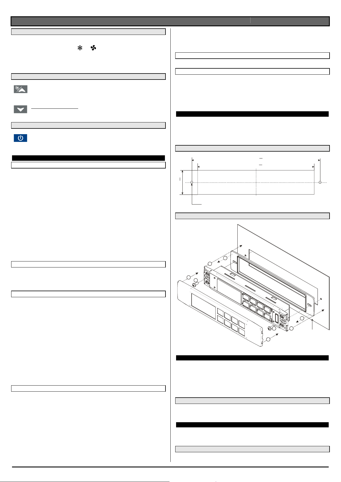
6.1 CUT OUT
165
150
31
+0.5
-0
+0.5
-0
+1
-1
Ø3 x2
6.2 MOUNTING
1
1
2
23
3
4
4
RG-LX gascke
(optional)
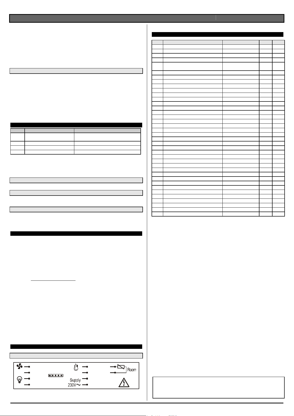
7. ELECTRICAL CONNECTIONS
The instruments are provided with Faston (2,8mm) to connect the analogue inputs. Relays and power
supply have a Faston connection (6,3mm). Heat-resistant cables have to be used. Before connecting
cables make sure the power supply complies with the instrument’s requirements. Separate the probe
cables from the power supply cables, from the outputs and the power connections. Do not exceed the
maximum current allowed on each relay, in case of heavier loads use a suitable external relay.
N.B. Maximum current allowed for all the loads is 20A.
7.1 PROBE CONNECTIONS
The probe shall be mounted with the bulb upwards to prevent damages due to casual liquid infiltration.
It is recommended to place the thermostat probe away from air streams to correctly measure the
average room temperature.
8. USE OF THE PROGRAMMING “HOT KEY “
The Wing units can UPLOAD or DOWNLOAD the parameter list from its own E2 internal memory to the
“Hot Key” and vice-versa.
8.1 DOWNLOAD (FROM THE “HOT KEY” TO THE INSTRUMENT)
1. Turn OFF the instrument by means of the ON/OFF key, remove the TTL serial cable if present,
insert the “Hot Key” and then turn the Wing ON.
dIXEL
Installing and Operating Instructions rel.1.0 - cod. 1598002153
1598002153 XW40LS GB VCS r1.0 06.12.2006.doc XW40LS 3/3
2. Automatically the parameter list of the “Hot Key” is downloaded into the Wing memory, the
“doL” message is blinking. After 10 seconds the instrument will restart working with the new
parameters.
3. Turn OFF the instrument remove the “Hot Key”, plug in the TTL serial cable, then turn it ON
again.
At the end of the data transfer phase the instrument displays the following messages:
“End “ for right programming. The instrument starts regularly with the new programming.
“Err” for failed programming. In this case turn the unit off and then on if you want to restart the
download again or remove the “Hot key” to abort the operation.
8.2 UPLOAD (FROM THE INSTRUMENT TO THE “HOT KEY”)
1. Turn OFF the instrument by means of the ON/OFF key and remove the TTL serial cable if
present; then turn it ON again.
2. When the Wing unit is ON, insert the “Hot key” and push okey; the "uPL" message
appears.
3. Push “SET” key to start the UPLOAD; the “uPL” message is blinking.
4. Turn OFF the instrument remove the “Hot Key”, plug in the TTL serial cable, then turn it ON
again.
At the end of the data transfer phase the instrument displays the following messages:
“end “ for right programming.
“err” for failed programming. In this case push “SET” key if you want to restart the programming again
or remove the not programmed “Hot key”.
9. ALARM SIGNALS
Message Cause Outputs
“P1” Thermostat probe failure
A
larm output ON; Compressor output according to
parameters “COn” and “COF”
“HA” Maximum temperature alarm Alarm output ON; Other outputs unchanged
“LA” Minimum temperature alarm Alarm output ON; Other outputs unchanged
“EE” Data or memory failure Alarm output ON; Other outputs unchanged
The alarm message is displayed until the alarm condition is recovery.
All the alarm messages are showed alternating with the room temperature except for the “P1” which is
flashing. To reset the “EE” alarm and restart the normal functioning press any key, the “rSt” message is
displayed for about 3s.
9.1 SILENCING BUZZER
Once the alarm signal is detected the buzzer can be silenced by pressing any key.
9.2 “EE” ALARM
The dIXEL instruments are provided with an internal check for the data integrity. Alarm “EE” flashes
when a failure in the memory data occurs. In such cases the alarm output is enabled.
9.3 ALARM RECOVERY
Probe alarm: “P1” (probe1 faulty), automatically stops 10s after the probe restarts normal operation.
Check connections before replacing the probe.
Temperature alarms “HA” and “LA” automatically stop as soon as the thermostat temperature returns
to normal values or when the defrost starts.
10. TECHNICAL DATA
Housing: self extinguishing ABS.
Case: facia 38x185 mm; depth 40mm
Mounting : panel mounting in a 150x31 mm panel cut-out with two screws. ∅3 x 2mm.
Distance between the holes 165mm
Frontal protection: IP65 with frontal gasket mod RG-L. (optional)
Connections: Faston 2.8mm for probe heat-resistant wiring and 6,3mm Faston for loads and supply
Power supply: 230Vac or. 110Vac ±10%
Power absorption: 4VA max.
Display: 3 digits, red LED, 14,2 mm high.
Inputs: 1 NTC or PTC probe
Relay outputs: Total current on loads MAX. 20A
compressor: relay SPST 20(8) A, 250Vac
light: relay SPST 8(3) A, 250Vac
fan: relay SPST 8(3) A, 250Vac
Other output : alarm buzzer (optional)
Data storing: on the non-volatile memory (EEPROM).
Kind of action: 1B.
Pollution grade: normal
Software class: A.
Operating temperature: 0÷60 °C.
Storage temperature: -25÷60 °C.
Relative humidity: 20÷85% (no condensing)
Measuring and regulation range: PTC probe: -50÷150°C (-58÷302°F)
NTC probe: -40÷110°C (-58÷230°F)
Resolution: 0,1 °C or 1°C or 1 °F (selectable).
Accuracy (ambient temp. 25°C): ±0,5 °C ±1 digit
11. CONNECTIONS
11.1 XW40LS
8(3)A Hot - Key
Fan Comp
20(8)A
8(3)A
N
L
N
N
Light
N
L
L
L
Max 20A
WARNING: Because of direct load connections, main voltage 230V is present in the faston of
loads, when the instrument is powered.
12. DEFAULT SETTING VALUES
Label
Name Range Default Level
REGULATION °C/°F
Set Set point LS÷US 2 Pr1
Hy Differential 0,1÷25,5 °C / 1÷45°F 1 Pr1
LS Minimum set point -50,0°C÷SET / -58°F÷SET -10 Pr2
US Maximum set point SET ÷ 110°C / SET ÷
230°F
10 Pr2
OdS Outputs activation delay at start up 0÷255 min. 1 Pr2
AC Anti-short cycle delay 0÷30 min. 1 Pr1
CCt Compressor ON time during fast freezing 0 ÷ 23h 50 min. 0 Pr2
COn Compressor ON time with faulty probe 0÷255 min. 15 Pr2
COF Compressor OFF time with faulty probe 0÷255 min. 5 Pr2
CH Type of regulation CL, Ht CL Pr2
DISPLAY
CF Temperature measurement unit °C ÷ °F °C Pr2
rES Resolution (integer/decimal point) in ÷ de dE Pr1
DEFROST
EdF Defrost mode In, Sd in Pr2
IdF Interval between defrost cycles 1÷120h 7 Pr1
MdF (Maximum) length for 1° defrost 0÷255 min. 60 Pr1
dFd Displaying during defrost rt, it, SEt, dEF, dEG it Pr2
dAd MAX display delay after defrost 0÷255 min. 30 Pr2
dPO First defrost after start up n ÷ y n Pr2
dAF Defrost delay after fast freezing 0 ÷ 23h 50 min. 0 Pr2
ALARMS
ALC Temperature alarms configuration rE÷Ab rE Pr2
ALU MAXIMUM temperature alarm -50,0÷110°C/ -58÷230°F 8 Pr1
ALL minimum temperature alarm -50,0÷110°C/ -58÷230°F 2 Pr1
AFH Temperature alarm differential 0,1÷25,5 °C / 1÷45°F 1 Pr2
ALd Temperature alarm delay 0÷255 min. 15 Pr2
dAO Delay of temperature alarm at start up 0 ÷ 23h 50 min. 1.3 Pr2
EdA Alarm delay at the end of defrost 0÷255 min. 20 Pr2
ANALOGUE INPUTS
Ot Thermostat probe calibration -12,0÷12,0°C / -21÷21°F 0 Pr1
OTHER
Pbc Kind of probe PbC, ntc ntc Pr2
rEL Software release - - - 2.0 Pr2
Ptb Map code - - - - Pr2
Prd Probes display Pb1 Pr2
Pr2 Access parameter list - - - Pr1
Dixell S.p.A. Via dell’Industria, 27
32010 Z.I Pieve d’Alpago (BL) ITALY
tel. +39 - 0437 - 98 33 - fax +39 - 0437 - 98 93 13
E-mail:[email protected] - http://www.dixell.com

Other dixell Thermostat manuals

dixell XR20Ce Wiring diagram

dixell

dixell XR20Ce Wiring diagram

dixell XR530D Wiring diagram

dixell

dixell XR530D Wiring diagram

dixell WING XW60L Wiring diagram

dixell

dixell WING XW60L Wiring diagram

dixell SE10-45-P User manual

dixell

dixell SE10-45-P User manual

dixell XR570C Instruction Manual

dixell

dixell XR570C Instruction Manual

dixell XH50P Instruction Manual

dixell

dixell XH50P Instruction Manual

dixell XR30C Instruction Manual

dixell

dixell XR30C Instruction Manual

dixell XR20CX Wiring diagram

dixell

dixell XR20CX Wiring diagram

Popular Thermostat manuals by other brands

Tech Controllers EU-R-8 PZ Plus user manual

Tech Controllers

Tech Controllers EU-R-8 PZ Plus user manual

Vive Comfort TP-N-731W Operation manual

Vive Comfort

Vive Comfort TP-N-731W Operation manual

RS PRO 124-1045 instruction manual

RS PRO

RS PRO 124-1045 instruction manual

ThermoLife 84 Series instructions

ThermoLife

ThermoLife 84 Series instructions

OLBA Thermotronic TS-TTD manual

OLBA

OLBA Thermotronic TS-TTD manual

Honeywell T6 Pro Hydronic user guide

Honeywell

Honeywell T6 Pro Hydronic user guide

EcoNet RETST800SYS user guide

EcoNet

EcoNet RETST800SYS user guide

Carrier 53DFST2-NP owner's manual

Carrier

Carrier 53DFST2-NP owner's manual

Salus VS35W Full user manual

Salus

Salus VS35W Full user manual

Emerson 1F85U-42NP Installation and operating instructions

Emerson

Emerson 1F85U-42NP Installation and operating instructions

Honeywell CT8602 owner's guide

Honeywell

Honeywell CT8602 owner's guide

Honeywell ST9400A user guide

Honeywell

Honeywell ST9400A user guide

Watts BT DP-01 user guide

Watts

Watts BT DP-01 user guide

Siemens TH 192 S installation instructions

Siemens

Siemens TH 192 S installation instructions

3M FIltrete 22 Operation guide

3M

3M FIltrete 22 Operation guide

Johnson Controls TEC2001-4 installation instructions

Johnson Controls

Johnson Controls TEC2001-4 installation instructions

Johnson Controls Hx3 S1-THXU430W User's information manual

Johnson Controls

Johnson Controls Hx3 S1-THXU430W User's information manual

DEVI devireg 316 Installation instruction

DEVI

DEVI devireg 316 Installation instruction

manuals.online logo
manuals.online logoBrands
  • About & Mission
  • Contact us
  • Privacy Policy
  • Terms and Conditions

Copyright 2025 Manuals.Online. All Rights Reserved.