Seite 2
Inhaltsverzeichnis
Table of contents
Montagehinweis
zur richtigen Verleimung der Arbeitsplatten-Stoßfugen
Assembly instructions
for the proper gluing of countertop seams
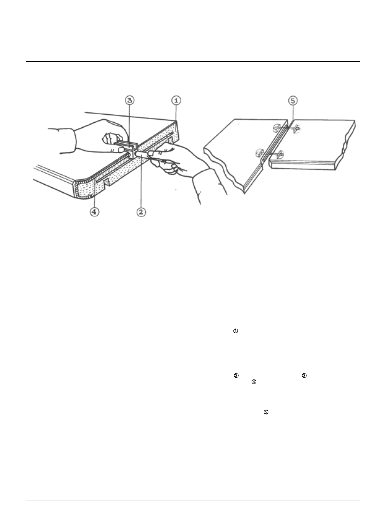
Stoßfuge auf Passgenauigkeit überprüfen (vorstehende Holzspäne im Bereich der Stoßfuge abschleifen).
Check to see the seams fit exactly. Sand off any wood shavings near the seam.
Stoßfuge reinigen.
Clean the seam.
Eine Seite der Stoßfuge im Bereich der unteren 3 cm mit wasserfestem Leim (EN 204) bestreichen.1
Spread water-proof glue (EN 204) on the lower 3 cm of one side of the seam. 1
Auf dem verbleibenden 1 cm Dichtungsmasse “Helmipur SH 100” wie folgt auftragen:
Tube 2in die Tuben-Auftrags-Schablone 3eindrehen. Unmittelbar vor dem Verschrauben der Arbeitsplatte
einen gleichmäßigen Wulst Dichtungsmasse auftragen. 4
Apply sealant (Helmipur SH 100) to the other 1 cm, as follows: Twist the tube 2into the tube applicator 3.
Immediately before screwing the countertop together, apply an even strip of sealant. 4
Arbeitsplatten zusammenfügen, ausrichten, Klammerverbindungen einsetzen und Schrauben anziehen.5
Join the countertop parts, align them, put in the clamp connector and tighten the screws. 5
Hervortretende Dichtungsmasse entfernen.
Reinigung der Arbeitsplatte mit einem mit Aceton oder Nitro-Verdünnung befeuchteten Tuch.
Remove any superfluous sealant. Clean the countertop with a cloth moistened with acetone or a cellulose thinner.
M 03
M 03 Zur richtigen Verleimung der Arbeitsplatten-Stoßfugen ...................................... Seite 03
For the proper gluing of countertop seams ..................................................... page 03
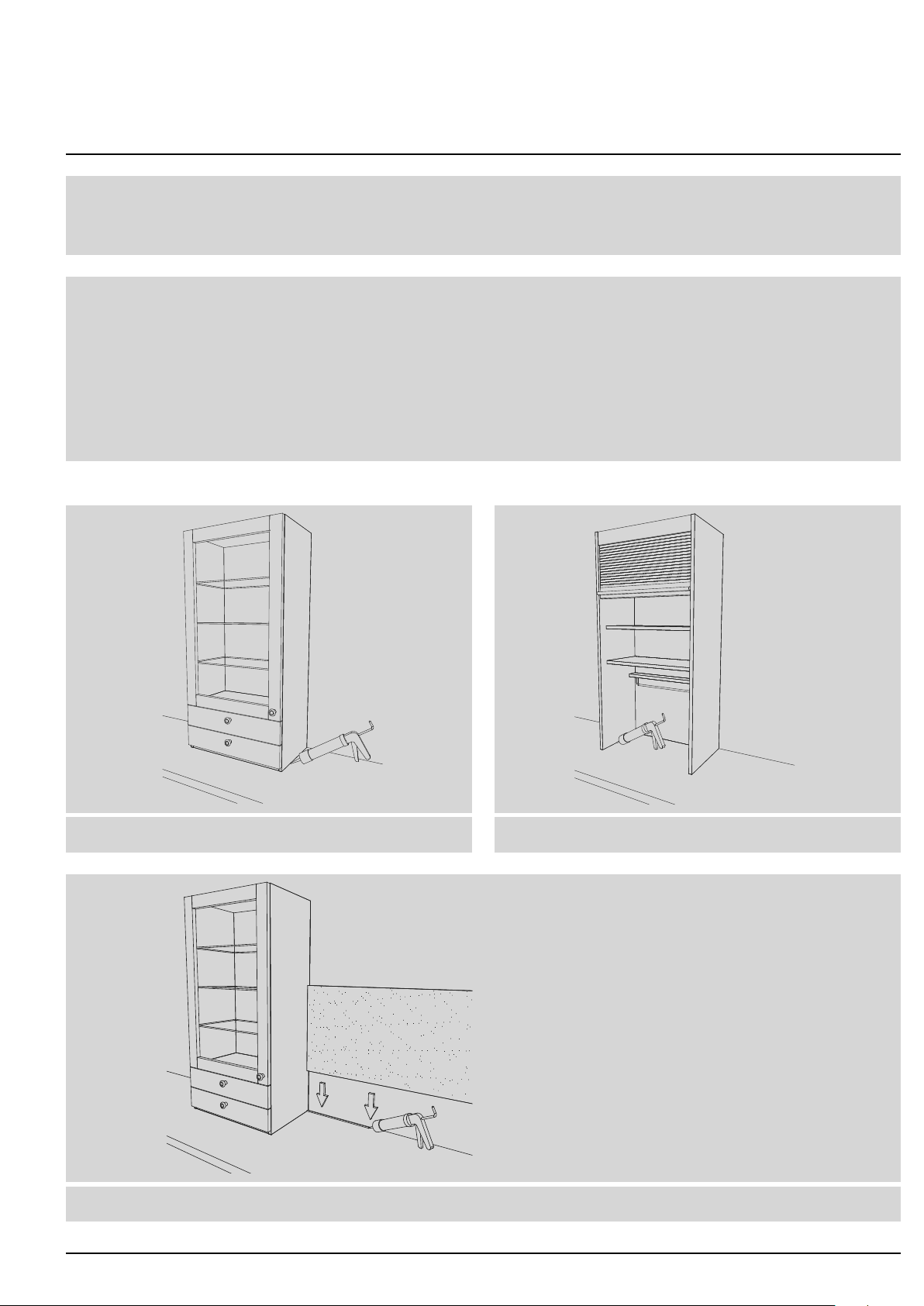
M 05 Wandbefestigung von 35 cm tiefen Schränken u. VRA Schränken ............................. Seite 04
Wall mounting of 35 cm deep units and VRA units ............................................... page 04
M 06 Blenden ..........................................................................Seite 05
Forllers ................................................................................. page 05
M 07 Spülen- und Herdmuldenausschnitt bei Arbeitsplatten in Verbindung mit Griffmuldenschränken ...... Seite 06
Sink and hob cut-out in countertops on base units with handle recess .............................. page 06
M 17 Div. Artikel, die zur Arbeitsplatte hin abgedichtet werden müssen .............................. Seite 07
Various units that must be sealed where they meet the countertop ................................. page 07
M 20 Griffmulde ........................................................................Seite 08
Handle recess ............................................................................. page 08
M 31 INTUO-P-Arbeitsplatten und -Wangenmontage............................................ Seite 09
INTUO-P countertops and mounting of end panels ............................................... page 09
M 36 Unterbau- u. Hochschrank-Korpusse 1,3 cm von der Wand vorgerückt ......................... Seite 10
Base unit and tall unit carcases 1.3 cm distance from the wall ..................................... page 10
M 37 Vertikale Griffmulde (GMH 62) ........................................................ Seite 11
Vertical handle recess (GMH 62) .............................................................. page 11
M 38 Schrankbefestigung ................................................................. Seite 12
Unit mounting .............................................................................. page 12
M 39 Bearbeitung von Materialien mit Acryl-Hochglanz-Oberächen................................ Seite 13
Handling materials with acrylic high-gloss surfaces .............................................. page 13
M 40 Befestigung der Steckfächer an Paneelrückwänden: ARW 4 SF3, HRW 4 SF6, SF GL, SF CP....... Seite 14
Mounting plug-in shelves on back panels: ARW 4 SF3, HRW 4 SF6, SF GL, SF CP ..................... page 14
M 44 Justierung von Vorrats-Vollauszugbeschlag (VRB) ......................................... Seite 15
Adjustingttingoffullyextendiblelarderunit(VRB) ............................................. page 15
M 46 Aufdopplungsleisten für Spülen- und/oder Kochmuldenausschnitte bei Dünn-Arbeitsplatten (DPL).... Seite 16
Additional slats for cut-outs for sinks and/or hobs in thin countertops (DPL) ......................... page 16
M 49 SBL-P Sockelblende mit U-Dichtprol und Gehrungs-Eckprol ............................... Seite 17
SBL-PPlinthwithU-sealingstripandmitrecornerprole ......................................... page 17
M 50 Wandhängende Schränke mittels Beschlag CAMAR 807 .................................... Seite 18
Wall-mountedunitswiththeuseofttingCAMAR807 ............................................ page 18
M 53 Edelstahl-Regal GROOVE ein- od. beidseitig offen; UCR xx ED (EO) .......................... Seite 19
StainlesssteelGROOVEshelf,openononesideoronbothsides;UCRxxED(EO) ................... page 19
M 54 Fronten-Ausrichtbeschlag ............................................................ Seite 20
Front-adjustmenttting...................................................................... page 20
M 55 Hinterfüllung für XXPL NV - Naturstein Verbund-Arbeitsplatten ............................... Seite 21
BackllingforXXPLNV-naturalstonecompositecountertops .................................... page 21
M 74 Blum CLIP top 107° Scharnier mit integrierter Scharnierdämpfung ............................ Seite 22
Blum CLIP top 107° hinge with integrated hinge damper .......................................... page 22
M 77 Laden und Rollkorb: Ein- u. Aushängen, Frontverstellung, Montage u. Demontage von Front ....... Seite 23
To put in and taken out drawers and pull-out units Mounting, removing and adjusting the front ......... page 23