3M Architectural Markets
3M U S
3M Center
Building 2207W07
St. Paul, MN 551441000
18886503497
3MArchitecturalMarkets.com
3M Canada
1840 Oxford St E
London, ON N5V 3 6
1-800-265-1840
3M is a trademark of 3M Company. Used under
license in Canada. © 3M 2014. All rights reserved.
Please recycle
98-0406-0071-4
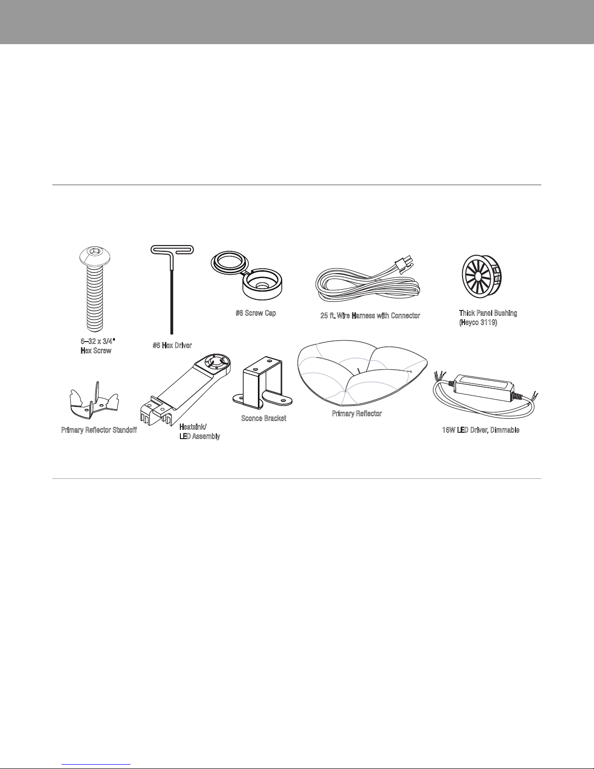
Installation Guide LIGHTFALLS by 3M™ + Todd Bracher
Sconce
WARRANTY DOCUMENT
Product
LIGHTFALLS by 3M™ + Todd Bra her (the “Produ t”) is a de orative LED lighting system for dry interior use (the “Appli ation”).
Limited Warranty
1. When used in the Appli ation, 3M warrants to the party who pur hased the Produ t dire tly from 3M (the “Buyer”) that the Produ t will be free from
defe ts in material and workmanship (the “3M Warranty”) for the appli able time period stated below (“Warranty Period”), whi h will begin on the
earlier of: (a) Produ t installation date; or (b) three months after 3M’s Produ t shipment date:
1.1 For all but a Produ t’s LED driver omponent, the Warranty Period is five years.
1.2 For a Produ t’s LED driver omponent, the Warranty Period is three years.
2. For Buyer’s onvenien e, 3M may provide a Spe ifi ation Sheet, other engineering or te hni al information, re ommendations, installation
instru tions, and other Produ t-related information or materials (all olle tively referred to as “Produ t Information”), but 3M does not warrant any
Produ t Information.
3. The 3M Warranty is ontingent on the Produ t being stored, wired, installed, maintained, and used only as 3M re ommends in all Produ t Information
and in this Warranty Do ument. Also, 3M has no obligation under the 3M Warranty as to Produ t that has been: (a) modified or altered in any manner;
(b) damaged through onta t with a person or thing, misuse, a ident, vandalism, negle t, or other a tion by anyone other than 3M; ( ) affe ted by
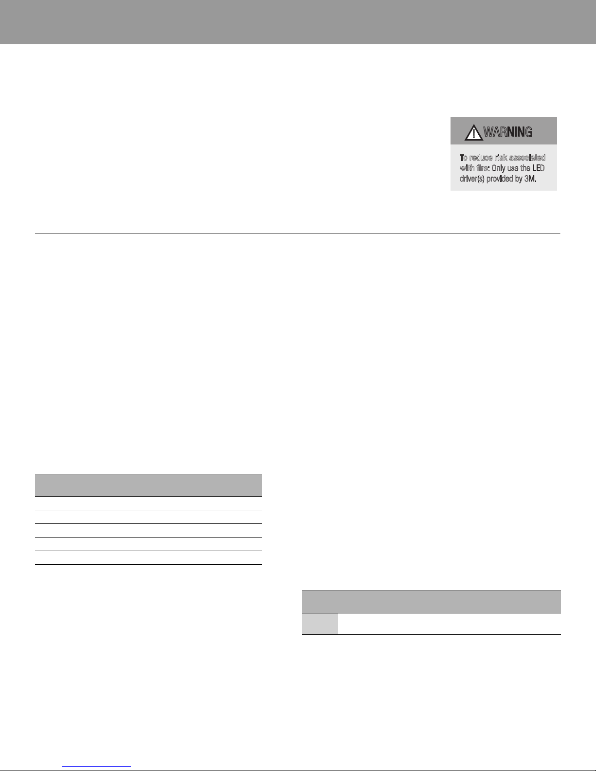
environmental onditions, su h as power flu tuations, improper LED driver, or a tivity by animals or inse ts; or (d) used not in omplian e with all
appli able standards and ele tri al odes.
4. EXCEPT TO THE EXTENT PROHIBITED BY APPLICABLE LAW, THE 3M WARRANTY IS MADE IN LIEU OF ALL OTHER WARRANTIES, RIGHTS OR
CONDITIONS, EXPRESS OR IMPLIED, STATUTORY OR OTHERWISE, INCLUDING, BUT NOT LIMITED TO, ANY IMPLIED WARRANTY OF MERCHANTABILITY,
SATISFACTORY QUALITY, FITNESS FOR A PARTICULAR PURPOSE AND THOSE ARISING FROM A COURSE OF DEALING, CUSTOM OR USAGE OF TRADE.
BUYER IS RESPONSIBLE FOR DETERMINING IF A PRODUCT IS SUITABLE FOR ITS PARTICULAR PURPOSE AND ITS INSTALLATION.
Limited Remedy
3M must re eive any 3M Warranty laim in writing by the earlier of: (a) appli able Warranty Period’s expiration date; or (b) fourteen business days after
Buyer’s dis overy of that 3M Warranty laim. If the Produ t is proven not to have met the 3M Warranty during the appli able Warranty Period, then BUYER’S
EXCLUSIVE REMEDY AND 3M’S SOLE OBLIGATION, WILL BE AT 3M’S OPTION, TO REPAIR OR REPLACE THAT PRODUCT QUANTITY OR REFUND THE APPLI-
CABLE PURCHASE PRICE.
Limitation of Liability
3M WILL NOT UNDER ANY CIRCUMSTANCES BE LIABLE TO BUYER FOR DIRECT (other than the Limited Remedy above), SPECIAL, INCIDENTAL, INDIRECT
OR CONSEQUENTIAL DAMAGES (INCLUDING, WITHOUT LIMITATION, LOSS OF PROFITS) IN ANY WAY RELATED TO A PRODUCT, THIS WARRANTY DOCU-
MENT, OR PRODUCT INFORMATION, REGARDLESS OF THE LEGAL OR EQUITABLE THEORY ON WHICH SUCH DAMAGES ARE SOUGHT.
Effecti e No ember 2013