3rd Power Kitchen Sink 6VEL User manual

USER’S GUIDE
GUITAR AMPLIFIER
™
DIRTY SINK 6VEL
™

2
Your 3RD POWER Amplifier is a professional musical instrument amplifier. The information
contained herein is current at the time of publication. However, specifications are subject to
change without prior notice.
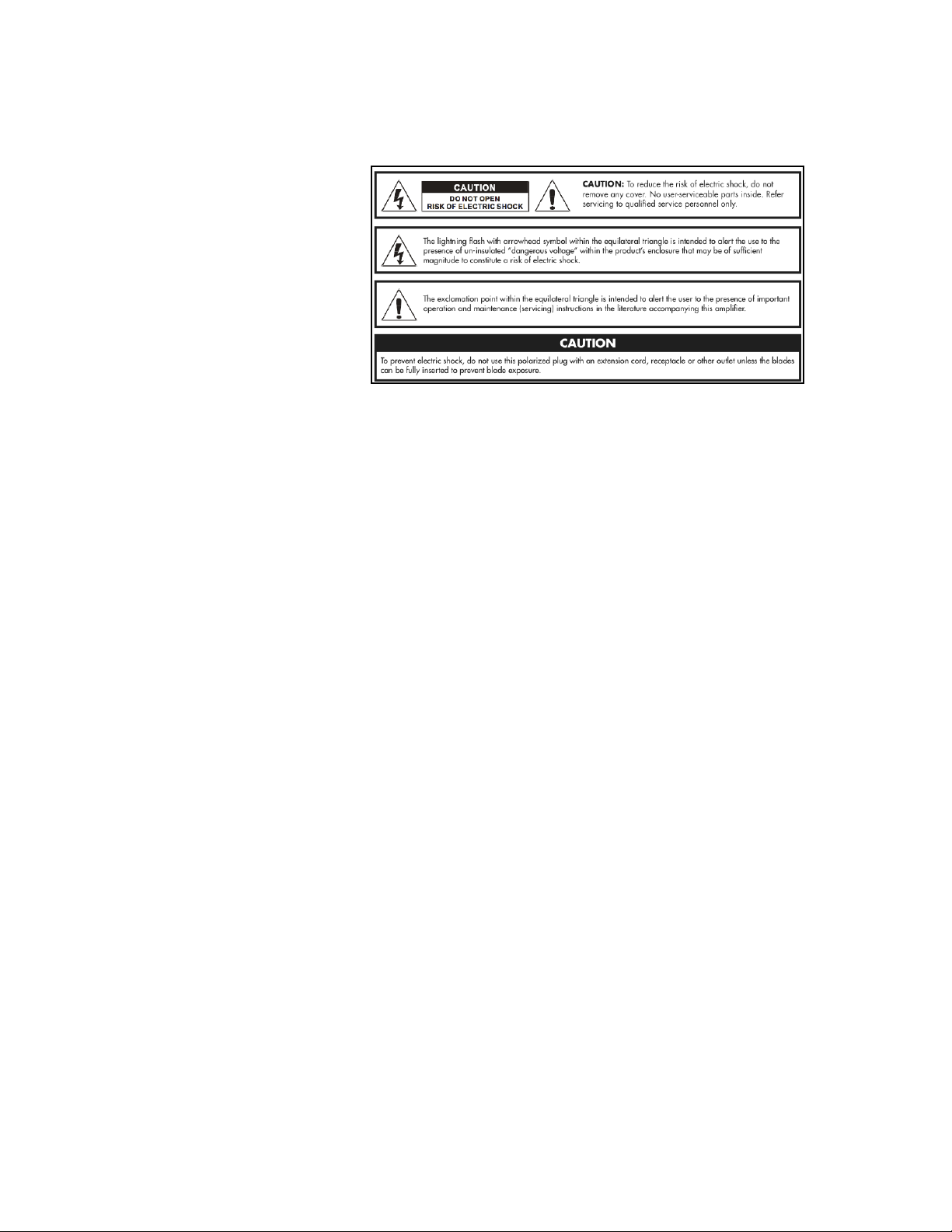
PRECAUTIONS & WARNINGS
• READ THESE INSTRUCTIONS.
• KEEP THESE INSTRUCTIONS.
• HEED ALL WARNINGS.
• FOLLOW ALL INSTRUCTIONS.
• YOUR AMPLIFIER IS LOUD!
EXPOSURE TO HIGH SOUND VOLUMES MAY CAUSE PERMANENT HEARING DAMAGE !
Practice “safe listening.”
• No user serviceable parts inside. Refer service to qualified personnel. Always unplug AC
power before removing chassis.
• IF YOU INTEND ON OPERATING THIS EQUIPMENT OUTSIDE OF THE USA: Always insure
that unit is wired for proper voltage. Make certain all connections and grounding con-
forms with local standards. Make certain that you have obtained authorization to operate
prior to connecting to power supply.
• WARNING: Vacuum tube amplifiers generate heat. To insure proper ventilation always
make certain there is at least four inches (100mm) of space behind the rear of the amplifi-
er cabinet.
• Keep away from curtains or any flammable objects.
• WARNING: Do not block any ventilation openings on the rear or top of the amplifier. Do
not impede ventilation by placing objects on top of the amplifier which extend past the
rear edge of its cabinet.
• WARNING: Do not expose the amplifier to rain, moisture, dripping or splashing water. Do
not place objects filled with liquids on or nearby the amplifier.
• WARNING: Always make certain proper load is connected before operating the amplifier.
Failure to do so could pose a shock hazard and may result in damage to the amplifier.
• Do not expose amplifier to direct sunlight or extremely high temperatures.
• Always insure that amplifier is properly grounded. Always unplug AC power cord before
changing fuse or any tubes. When replacing fuse, use only same type and rating.
• Avoid direct contact with heated tubes. Keep amplifier away from children.
• Be sure to connect to an AC power supply that meets the power supply specifications
listed on the rear of the unit. Remove the power plug from the AC mains socket if the unit
is to be stored for an extended period of time. If there is any danger of lightning occurring
nearby, remove the power plug from the wall socket in advance.
• To avoid damaging your speakers and other music equipment, turn off the power of all
related equipment before making the connections.
• Do not use excessive force in handling control buttons, switches and controls. Do not
use solvents such as benzene or paint thinner to clean the unit. Wipe off the exterior with
soft cloth.

3
Thank you for choosing the Dirty SINK 6VEL by
3RD POWER as an integral component of your
musical journey.
Music is a thrilling blend of tone, attitude and
technique.When the right combination occurs,
magic happens and it’s experienced by every-
one.
I’ve had the extraordinary privilege of per-
forming music for over 30 years on stage and in
the studio.As the principal visionary of the company, every product we design reflects my energy, atti-
tude and life experiences.
Each amplifier we create is designed to help you tell your musical story - IN 3D!!!
Rock on!
- Dylana Nova Scott
MOVING FORWARD... IN 3D

4
Special Features of the DIRTY SINK 6VEL™:
• British Voiced Plexi & Cascaded Preamp Section (switchable)
• Dual-mode 3-Band EQ (JTM/JMP – switchable)
• Tube Buffered FX Loop (foot-switchable)
• Preamp Gain Boost (foot-switchable)
• Preamp Bias Selector (4 position switch from cold to warm)
• HybridMaster, plus foot-switchable lead boost
• 6V6 (~20W) or 5881/EL34/6L6 (~35W and up) Operation
• Back-panel Bias Test Points and Adjustment Pot
• Over-sized /Overbuilt Power Transformer and Power Supply
• 4 Button Pro Foot Switch & 7 Pin Cable (included)
• Hand-wired and Hand Built (point to point) in Nashville,TN
• Limited Lifetime Warranty
New Technology (Preamp Bias Switch)
The Preamp Bias control features 4 bias presets!that range from “cold” bias to “warm” bias. Cold bias-
ing is a technique that reduces the!amount of electrical current flowing through a tube gain stage.
The lower bias, the smaller the the current – and the amplification!performance of the!gain stage
occurs in a!different portion of the tubes performance range. This can dramatically alter the tone and
feel in unique and pleasing ways.
Foot-switchable Hybrid-MASTER Bypass (boost function)
Create custom volume level presets perfect for setting up a rhythm and lead volume scene changes
for recalling them live via foot-switch.
Accessories:
A high-quality slip cover is available.
Dimensions & Weights:
Subject to change anytime. Please measure your amp carefully if a custom case is being made. These
measurements do not include handle and rubber feet.
Head:!19-7/8” x 8.5” x 9”
Weight: 20 lb.
112 Combo: Dimensions (WxHxD): 19-7/8” x 16” x 9-7/8”
Weight: 31 lb.

5
Preparing to Operate your Dirty SINK 6VEL™
Make certain that all connections are made prior to operating your amplifier including power cable,
speaker connection, instrument cable and instrument connection. Make certain that all tubes are in-
stalled.
Input Jack (1)
The INPUT jack is where you connect instrument level signals.
Gain Control (2)
The GAIN control allows you to adjust the signal gain level as well as the temperament and overall
character of your instrument’s sound. Clean tones are at the lower end of the control dial. Preamp
saturation, distortion and compression increase as you go higher on the dial.
Volume Control (3)
The VOLUME control allows you to adjust the signal level that feeds the FX Loop circuitry. When you
have the GAIN control at lower settings, you will tend to run this control higher up (1 to 2 o’clock).
When you have the GAIN control at higher settings, you will tend to run this control in the mid to
lower setting range (10 to 11 o’clock).
Treble Control (4)
The TREBLE control allows you to adjust the character of the higher frequency range.
Middle Control (5)
The MIDDLE control allows you to adjust the emphasis of the mid-range frequencies.
Bass Control (6)
The BASS control allows you to adjust the depth of your lower frequencies.
Front Panel (Section One):
1
2
3
4
5
6

6
Preamp Bias Control (7)
The PREAMP BIAS control features 4 bias presets!that range from “cold” to “warm”. With lower bias
settings, a preamp tube amplifies in a!different portion of the tube’s performance range.This can
dramatically alter the tone and feel in unique and pleasing ways.
For example, it is possible to craft a!tighter guitar!signal with a more focused dynamic response
when running a gain stage with a lower bias current (cold bias). Conversely, it is possible to craft a
fat, open guitar signal that is somewhat!ambient in the way it loosens up when running a gain stage
with a higher bias current (warm bias). !
With the DIRTY SINK 6VEL’s Preamp Bias control, it’s possible to craft classic, open vintage British
flavored tones as!well as more modern, focused higher gain tones and anything in between. Pre-
paring to Operate your Dirty SINK 6VEL™
Presence Control (8)
The global PRESENCE control affects both channels and allows you to adjust the character or ‘for-
wardness’ of your sound. Low settings create ‘darker’ tones, whereas higher settings create a ‘brilliant’
or crisp sound.
Standby Switch (9)
The STANDBY switch, when placed in the DOWN position, puts the amplifier in ‘standby mode’ allow-
ing the tubes to warm up.When this switch is place in the UP position, the tube circuitry is fully func-
tional and ready to amplify your guitar signal.
Power Switch (10)
The POWER switch, when placed in the UP position, provides AC wall power to the amplifier.
Front Panel (Section Two):
10
9
7
8

7
Cascade/Plexi Switch (12)
Set to Plexi Mode, you’ll find classic British clean to crunch tones. Set to Cascade Mode, you’ll find
tones ranging from soaring solos to modern saturation.
System Mute Indicator (13)
With the System Mute function, guitar tuning and swapping instruments eliminate on stage!distrac-
tions.This is great way to keep the stage quiet in between songs as well.Tuners that mute are fine,
but higher gain amplifiers will still “hiss” in the background. With!System Mute,!you’ll have a silent
stage between songs. Overdubs in the studio will be tighter as well.
+Gain Switch & Indicator (14)
Additional preamp gain can be engaged or assigned to fall under foot!switch command. This is ideal
for adding additional gain/sustain to solos.The indicator tells you when you’ve added more gain.
Tone Stack Switch (15)
The Tone Stack voicing switch lets you select the sweeter JTM tone control voicing and balanced
gain response in one position, and the more in your face JMP voicing in the other.
Boost/FTSW Bus Indicator (16)
Cue your own solos with the on-board lead boost function. This indicator lets you!know when you’ve
engaged the solo boost.
FX Loop Status Indicator (17)
Nothing!finishes out your lead tone like the perfect delay tap or multi-FX patch. Now you can have a
complex tone!without a complex setup. Just patch your favorite FX!device in the all-tube buffered
loop with the shortest cables possible and set it to your favorite patch. When you turn on the loop,
your lead tone will now be complete!
Front Panel (Section Three):
13
15
12
14
16
17

8
Back Panel (Section One):
18
19
16Ω
OHM SELECTOR
4Ω
8Ω
FA N
H.T. Fuse (18)
The H.T. FUSE requires a 0.25 AMP (250 milliamp) slow-blow fuse.The H.T. FUSE usually blows if your
power tubes are bad to protect the circuit from being damaged.
AC Fused Input (19)
The AC FUSED INPUT socket (TYPE IEC Grounded) is a required connection for operating your DIRTY
SINK 6VEL at 120V (standard USA household electrical power).The MAINS FUSE requires a 2.5 AMP
slow blow fuse.This fuse protects your amplifier from voltage peaks from your power outlet.
SAFETY NOTES:
• Always plug your amp into a properly grounded 3 prong AC outlet.
• Never plug your amp into an ungrounded outlet.
• Never remove or break off the 3rd prong safety ground pin from the power cord.
• Never use a damaged or ungrounded power cord.
• Always use the proper value and type fuse according to the rear-panel markings.
• Never attempt to replace the fuse while the amplifier is still plugged into the power source.The
fuse should only be replaced when the power cord has been disconnected from its power source.

9
16Ω
OHM SELECTOR
4Ω
8Ω
FA N
Back Panel (Section Two):
20
21
Impedance Selector (20)
The 16-OHM SPEAKER position is provided for connecting your amplifier to standard 16 OHM
speaker cabinet.The 8-OHM SPEAKER position is provided for connecting your amplifier to a single
8-OHM, or two 16-OHM speaker cabinets.The 4-OHM SPEAKER position is provided for connecting
your amplifier to a single 4-OHM, or two 8-OHM speaker cabinets.
Speaker Jacks (21)
The SPEAKER OUTPUTS are wired in parallel.
SAFETY NOTES:
• Never operate your amplifier without a connected speaker cabinet.This will damage your tubes
or transformers - or both.
• Always operate your amplifier with the proper impedance output that matches your speaker cab-
inet(s).
• In all cases, always use a good quality heavy gauge speaker cable (not a shielded instrument ca-
ble) to connect your DIRTY SINK 6VEL to the speaker cabinet(s).
Hybrid-MASTER™ Control (22)
The proprietary HYBRID-MASTER control allows you to set the overall volume level of the amplifier
independent of the volume and tone settings established on the front panel. The MAIN control is
always active and sets the minimum volume of the amplifier (rhythm volume).
HM Bypass Control (23)
Create custom volume level presets perfect for setting up a rhythm and lead volume scene changes
for recalling them live via foot-switch.
(See next page for sample settings.)
22
23

12
16Ω
OHM SELECTOR
4Ω
8Ω
FA N
Back Panel (Section Three):
Foot Switch Connector (24)
To remotely control channel selection, preamp gain boost, FX loop on/off and Hybrid-Master bypass
(lead boost), connect the foot pedal with the 7-pin DIN cable (both the pedal and cable are included
with purchase).
OPERATION NOTES:
The remote foot-switch allows you to put the DIRTY SINK’s 6VEL advanced features under foot con-
trol. The unit includes a high quality 15’ 7-Pin DIN cable with a straight plug for the back of the amp
and a right angle plug for use at the pedal. The amplifier provides phantom power through the cable
to drive the LEDs.
• +GAIN: Select FTSW on the +GAIN mini toggle switch located in between the Gain and Volume
control of channel two on the front panel of the amplifier. You may now remotely control your
channel extra gain function.
• Hybrid-MASTER Bypass (Boost): The Hybrid-Master bypass is permanently connected to the FS
Bus circuit. Should you wish to disable the boost, simply turn the Bypass control to zero (fully
counter-clockwise). See page 10 for suggested setting for best use.
• FX Loop On/Off: On the back panel of the amp, place the mini toggle switch in the FTSW posi-
tion. This assigns the loop on/off to the FS Bus. With both +Gain and FX Loop assigned, an ex-
cellent lead solo preset is created where additional gain and sustain come from the preamp, any
effect (such as digital delay) engages, and the volume increases to your specified preset level -
all with the stomp of a single button on your foot switch.
WARNING:
The DIRTY SINK 6VEL foot switching system cannot share an electrical ground with any other device.
Care should be used when placing your 4 Button foot switch with other devices on a pedal board or
metal tray so as to keep the unit isolated from metal to metal contact.
24

10
Back Panel (Section Four):
Sample Settings:
When in rehearsals (or on a live TV set), adjust the HYBRID-MASTER to 8 o’clock (this will be your
rhythm volume).Adjust HM BYPASS to 8 o’clock (this will be your lead volume).When you press the
HM BYPASS switch located on the 4 Button Pro foot switch, the volume will toggle between rhythm
level and lead level. Fine tune to your application.
When performing live on stage, adjust the HYBRID-MASTER to 10-11 o’clock (this will be your
rhythm volume).Adjust HM BYPASS to 4-5 o’clock (this will be your lead volume).When you press the
HM BYPASS switch located on the 4 Button Pro foot switch, the volume will toggle between rhythm
level and lead level. Fine tune to your application.
16Ω
OHM SELECTOR
4Ω
8Ω
FA N
16Ω
OHM SELECTOR
4Ω
8Ω
FA N
Sample Rehearsal Setting
Sample Gig Setting
4 Button Pro Foot Switch
The 4 Button Pro ships with the Dirty SINK 6VEL. It gives you total command over Active and Mute
mode, Preamp Gain, FX Loop Bypass and Solo Boost with a single button assigned to each feature.
FTSW Bus Assign Switch (25):
With this feature, it is possible to engage additional preamp gain, turn on the FX Loop and cue your
own lead solo volume levels all on a single button. In the up position, each mini toggle switch will
send the selected feature to the FTSW Bus foot switch (far right button). In the down position, each
feature will remain controllable by their allocated foot switch button.
25

11
16Ω
OHM SELECTOR
4Ω
8Ω
FA N
Back Panel (Section Five):
26
Tube Effects Loop
Experience STUDIO QUALITY TONE from your pedals or multi-effects units by running them through
the loop. The loop on your Dirty SINK 6VEL can also be placed under foot switch control.
FX Send Jack (26)
This 1/4” mono Tip/Sleeve jack feeds signal to your effects device.
FX Return Jack (27)
This 1/4” mono Tip/Sleeve jack accepts the return signal from your effects device.
FX Loop Operation Switch (28)
Choose LOCAL to retain the loop in the signal chain at all times. Choose FTSW to place the loop un-
der command of your foot switch controller (either the included foot switch or a 3rd party switching
system).
OPERATION NOTES:
• Signal levels at the FX SEND jack are a nominal -10dBV (just under 1V p-p) matching the levels
most vintage and modern effect pedals want to see.
• The FX RETURN path brings your signal back into the amplifier with a tremendous amount of
headroom (accepting signals as low as -10dBV and as high as +4dBU before the onset of com-
pression).
• It can also be a gig-saver too. If your pedal board ever goes down during a performance, you can
plug your guitar straight into the FX RETURN jack and get through a song with quality tone.
CAUTION:
Avoid “hot swap” any cables connected to the loop while the amplifier is operational. Before break-
ing any connections, make sure that your amp is on Standby. Failure to do so may result in a loud
pop, hum or buzz that could potentially damage your speaker.
27
28

13
16Ω
OHM SELECTOR
4Ω
8Ω
FA N
Back Panel (Section Six):
29
30
31
32
CAUTION:
NEVER touch hot tubes!!! Temperatures can exceed 500˚F and cause severe burns!
CAUTION:
Read all of the information and procedures in this section before attempting to modify the factory
bias settings of your amplifier.
Power Tube Bias Adjustment Control (29)
Controls the amount of negative DC bias voltage being fed into both output tube input grids. Insert
a mini flathead screw driver into control port and rotate counter-clockwise to lower the idle current
setting (operate cooler). Rotate clockwise to increase the idle current setting (operate hotter).
V5+ Voltage Reading Terminal (30)
This terminal is internally connected to a one-ohm resistor on the output tube cathode of V5 (the
power tube on the right). When monitoring the current here, you will be reading millivolts on your
portable multimeter. You will need to connect your positive (+) test lead (typically red) to this termi-
nal.
GND- Terminal (31)
This terminal is internally connected to chassis ground. When monitoring the current of either out-
put tube, you will need to connect the negative (typically black) test lead here.
V6+ Voltage Reading Terminal (32)
This terminal is internally connected to a one-ohm resistor on the output tube cathode of V6 (the
power tube on the right). When monitoring the current here, you will be reading millivolts on your
portable multimeter. You will need to connect your positive (+) test lead (typically red) to this termi-
nal.

14
16Ω
OHM SELECTOR
4Ω
8Ω
FA N
Back Panel (Power Tube Biasing):
CAUTION:
NEVER touch hot tubes!!! Temperatures can exceed 500˚F and cause severe burns!
Biasing your tube amplifier need not be a scary endeavor as the process is pretty straightforward.
Heed all warnings, cautions and instructions and you should do fine. If you’re unsure or unclear on
the process, do not attempt to manipulate the bias from factory settings. If, during the biasing
process,you hear a loud “pop” or see a tube “flash” immediately power down the unit and seek a
qualified tube amplifier repair/service technician.
OPERATION NOTES:
• Monitor your output tube bias at idle current. To achieve idle current, your amp must be turned
on and operating at idle (no audio signal being fed into the input or the FX loop return). Make
sure that your speaker is plugged in.
• Attach the negative test lead from your multimeter to the GND- terminal (black) on the back
panel of the amp.
• One at a time, attach the red (positive) test lead from your multimeter to either V8+ or V9+ ter-
minals (red) and note the reading on your meter. Then read the voltage on the other tube. The
resulting numbers should be within 6mv of each other. Note that your maximum bias setting
must be based off of the higher number.
• To optimize your output tube bias, adjust the control screw by inserting a mini flathead screw
driver into control port (see diagram and description for item number (28)). Turn clockwise to
bias your tubes ‘hotter’ (increasing the idle current) and counter-clockwise to bias your tubes
‘cooler’ (decreasing the idle current).
• Cooler settings (lower idle current) can increase the life of your tubes. Too cool and the sound
will tend to be brash and one dimensional.
• Optimal tone and feel can be found when the bias range is around 50% - 70% of your tube’s
maximum operating range. This will vary between the types of tubes you choose to operate your
amp with.
• Should you wish to swap to the other set of tubes, you must do so in like-kind pairs as mixed
tubes will not operate correctly and may be hazardous to your amplifier. You can safely substi-
tute either rectifier tube. Again, use caution to mount the correct tubes in the appropriate tube
sockets.

15
Tube Layout and Requirements:
V1: JJ 12AX7 (Preamp)
V2: JJ 12AX7 (Tone Stack)
V3: JJ 12AX7 (FX Loop)
V4: Sovtek 12AX7LPS (Phase Inverter)
V5 and V6: EL34 Output tubes
Swapping Tubes and Bias Adjustment
Your DIRTY SINK 6VEL comes from the factory biased for safe operation of the factory provided tubes.
Limited bias adjustments are available to the user via the back panel bias terminals. Follow the rec-
ommended procedures and bias settings at all times and note the highlighted warning and caution
alerts as your safety as well as the safe operation of your amplifier depend on it.
The operating range of the user bias circuit has been limited as a precaution while retaining enough
adjustment potential in order to provide the necessary flexibility to operate a wide range of compat-
ible tubes available on the market.
Under no circumstances should you open your amplifier and attempt to modify the circuitry in order
to increase operating range. Attempting to do so will potentially expose you to very dangerous high-
voltage electricity that can kill you. DO NOT ATTEMPT TO DO THIS YOURSELF.
Tube Replacement
THE SAFEST WAY TO CHANGE YOUR TUBES WOULD BE TO TAKE YOUR AMPLIFIER TO A QUALIFIED
TECHNICIAN FOR SERVICING. To safely change your own tubes at home: Make certain the amplifier
is turned off and has been allowed ample time to cool down.
WARNING:
Never touch the tubes while the amplifier is turned on or has recently been turned ON. You can se-
verely burn your fingers and hands. Tubes are made of glass and can break if mishandled.
WARNING:
Do not touch the tube pins as you remove the tube. Even after turning your amp off and unplugging
it from the power outlet there could be enough voltage stored in the capacitors to give you a lethal
electrical shock.
POWER
TRANSFORMER
OUTPUT
TRANSFORMER
CHOKE
CAN
CAPACITOR V1V2
V3V4
V5
V6
Tube Layout/Socket Location:

16
Power Tube Biasing: Factory Settings
Power Tube
~Plate
Voltage
~Bias
(milliamps)
~Wattage @ Idle/
Dissipation
Safety Range
JJ Electronics 6L6GC
422V
40-45
~38W (65%)
Average (Factory)
JJ Electronics E34L
430V
35-40
~30W (60%)
Average (Factory)
JJ Electronics 6V6GC
442V
21
18W (65%)
Average (Factory)
Factory Settings:
Your amplifier ships with the bias settings optimized for maximum flexibility and safety. During QC
and final testing, the bias is set maximum safe power dissipation (approximately 60-65% of a given
tube’s performance rating).

17
LIMITED WARRANTY
Thank you for choosing 3RD POWER Amplification. 3RD POWER takes great pride in producing high-quality tube
amplifiers and speaker cabinets. Each product is thoroughly tested prior to shipment.
Your amplifier is warranted to the original purchaser to be free from defects in material and workmanship for a
period of 10 years from the original date of purchase.An original sales receipt will establish coverage under this
warranty.This warranty does not cover service or parts to repair damage caused by accident, neglect, abuse, nor-
mal wear, disaster, misuse, over-powering, negligence, inadequate packing or shipping procedures and service,
repair or modifications to the product which have not been authorized by 3RD POWER. If this product is defective
in materials or workmanship as warranted above, your sole remedy shall be repair or replacement as provided
below.
Tubes: 3RD POWER warrants the original purchaser that the tubes used in the unit will be free from defects in
material and workmanship for a period of 30 days from the original purchase date.A dated sales receipt will es-
tablish coverage under this warranty. This warranty is in lieu of all other expressed warranties. If tubes fail within
the initial 30 day period your sole remedy shall be the replacement of tubes as provided below.
Return Procedures: In the unlikely event that a defect should occur, follow the procedure outlined below. Defec-
tive products must be shipped, together with proof of purchase, freight pre-paid and insured directly to 3RD
POWER. A Return Authorization Number must be obtained prior to shipping the product. Contact 3RD POWER to
obtain this RA number. Products must be shipped in their original packaging or equivalent. IN any case, the risk of
loss or damage in transit is borne by the purchaser. The RA number must appear in large print directly below the
shipping address.Always include a brief description of the defect, along with your correct return address and
telephone number.
When calling to inquire about a returned product, always refer to the RA number. If 3RD POWER determines that
the unit was defective in materials or workmanship at any time during the warranty period, 3RD POWER has the
option of repairing or replacing the product at no additional charge, except as set forth below. All replaced parts
become property of 3RD POWER. Products replaced or repaired under this warranty will be returned via ground
shipping within the United States, freight prepaid. 3RD POWER is not responsible for costs associated with expe-
dited shipping, either to 3RD POWER or returned of the product to the customer.
Incidental or Consequential Damage: In no event will 3RD POWER be liable for any incidental or consequential
damages arising out of the use or inability to use any 3RD POWER product, even if a 3RD POWER dealer has been
advised of the possibility of such damages or any other claim by any other party. Some states do not allow the
exclusion or limitation of consequential damages, so the above limitation and exclusion may not apply to you.
This warranty gives you specific legal rights and you may also have other rights which may vary from state to
state.
For your protection: Please complete and mail the Purchase Information Card within (10) ten days of the date of
purchase so that we may contact you directly in the event a safety notification issued in the accordance with the
1972 Consumer Product Safety Act.
Customer Support: Our dedicated staff is ready to assist you should you have any questions with regard to your
product. Please call: (615) 945-3393 (9:00 AM to 5:00 PM Monday through Friday, Central Standard Time).
Other manuals for Kitchen Sink 6VEL
1
Table of contents
Other 3rd Power Musical Instrument Amplifier manuals

3rd Power
3rd Power Dream 40 American User manual

3rd Power
3rd Power AMERICAN DREAM MKII User manual

3rd Power
3rd Power Kitchen Sink 6VEL User manual

3rd Power
3rd Power BRITISH DREAM MKII User manual

3rd Power
3rd Power KITCHEN SINK User manual

3rd Power
3rd Power CLEAN SINK MKII User manual

3rd Power
3rd Power Wooly Coats Spanky MKII User manual

3rd Power
3rd Power WOOLY COATS EXTRA SPANKY User manual