A computer keyboard with USB interface.
A computer mouse with USB interface.
Starting the board for the first time
To start the board, follow these simple steps:
1. Connect the HDMI cable to the ROCK960 Board HDMI connector and to the LCD
Monitor.
2. Connect the keyboard to USB connector marked USB2.0 and the mouse to the USB
connector marked USB3.0. (It doesn’t matter which order you connect them in.)
3. Plug the power supply into the power outlet.
4. The system will automatically boot when the power supply is connected.
Back to top
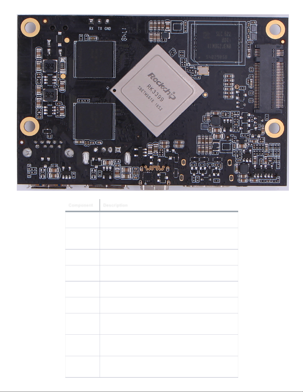
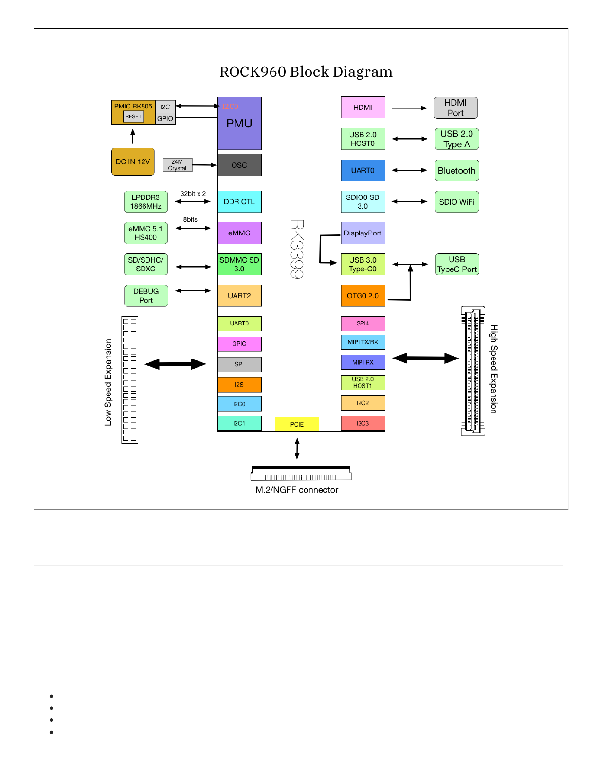
Component Details
Processor
RK3399 is a low power, high performance processor for computing, personal mobile
internet devices and digital multimedia devices; it integrates dual-core Cortex-A72
and quad-core Cortex-A53. RK3399 supports multi-format video decoders including
H.264/H.265/VP9 up to 4Kx2K@60fps, especially, H.264/H.265 decoders support
10bits coding, and also supports H.264/MVC/VP8 encoders by 1080p@30fps, high-
quality JPEG encoder/decoder, and special image preprocessor and postprocessor.
RK3399 has high-performance dual channel external memory interface (2x32bit
LPDDR3) capable of sustaining demanding memory bandwidths. Learn more
at RK3399 Product Page.
PMIC
The PMIC on ROCK960 is RK805, a companion PMIC for RK3399 by Rockchip.
The RK805 is a complete power supply solution for portable systems. The highly
integrated device includes four buck DC-DC converters, three high performance
ldos, I2C interface, programmable power sequencing and an RTC.
The RK805 improves performance, reduces component count and size, and
therefore provides lower cost solution compared to conventional portable designs.