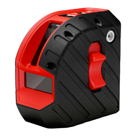
A/DA Vertical User manual

Инструкция
по эксплуатации
Прибор вертикального проектирования ADA Vertical
А00364
Цены на товар на сайте:
http://www.vseinstrumenti.ru/instrument/izmeritelnyj/teodolity/ada/pribor_vertikalnogo_proektirovaniya_
ada_vertical_a00364/
Отзывы и обсуждения товара на сайте:
http://www.vseinstrumenti.ru/instrument/izmeritelnyj/teodolity/ada/pribor_vertikalnogo_proektirovaniya_
ada_vertical_a00364/#tab-Responses

Operating manual
Instrument of vertical projection
Model: ADA Vertical
Manufacturer Address .

VERTICAL
Table of contents
1. Description and application . . . . . . . . . . . . . . . . . . . . . . . . . . . . . . . . . . . . . . . . . . . . . . . . . . . . . . . . . . . . . . . . . 3
2.
3. Construction features . . . . . . . . . . . . . . . . . . . . . . . . . . . . . . . . . . . . . . . . . . . . . . . . . . . . . . . . . . . 6
4. Preparation before operation. . . . . . . . . . . . . . . . . . . . . . . . . . . . . . . . . . . . . . . . . . . . . . . . . . . . . . . . . 7
5. Measurements. . . . . . . . . . . . . . . . . . . . . . . . . . . . . . . . . . . . . . . . . . . . . . . . . . . . . . . . . . . . . 9
6. Adjustment of the instrument . . . . . . . . . . . . . . . . . . . . . . . . . . . . . . . . . . . . . . . . . . . . . . . . . . . . . . . . . . . . . 9
7. Maintenance . . . . . . . . . . . . . . . . . . . . . . . . . . . . . . . . . . . . . . . . . . . . . . . . . . . . . . . . . . . . . . 11
8. Warranty . . . . . . . . . . . . . . . . . . . . . . . . . . . . . . . . . . . . . . . . . . . . . . . . . . . . . . . . . . . . . . . . 12
9. Exceptions from responsibility . . . . . . . . . . . . . . . . . . . . . . . . . . . . . . . . . . . . . . . . . . . . . . . . . . . . . . . . . . . . . . . 12
Appendix 1. Warranty card
Appendix 2.

MEASUREMENT FOUNDATION
VERTICAL
3
ADA VERTICAL presents the instrument of vertical projection with laser emitter, class 2. Do not look into the laser beam
and do not aim at other persons.
1. Description and application
1) Transmission of planned position with the help of optical method or laser beam;
2) Bright visible red laser beam (635nm);
3) Brightness adjustment of laser beam;
5) Laser target with reticular division;
6) Bubble levels with LED backlight;
Laser beam is combined with axis of sight of telescope. Such alignment is very convenient when measuring. Because
it’s possible to make optical and laser measurements simultaneously. With the help of telescope it’s possible to control
the position of laser spot and transmit planned position of the dot in vertical direction.
Instrument of vertical projection is widely used by professionals for control when building elevator well, setting supports
for high-tension lines, building bridges and tunnels, skyscrapers, water towers, chimneys and for other works where it’s
necessary to have constant control.
Complete set
- instrument of vertical projection 1
- operating manual 1
- target plate 1
- calibrating pin 1
- case 1
- batteries 2

VERTICAL
MEASUREMENT FOUNDATION
4
Limit deviation of the plumb up
Limit deviation of the plumb down
Accuracy of tubular level
Optics and laser plumb (zenith)
Image inverted
Angle of view 1° 50’
Effective aperture of lens 36 mm
0,8 m
Laser wavelength 635 nm
Range of laser viewing 70 m
Laser range in the daytime<200m ; at night<250m
Laser power 5mW
Diameter of laser spot
Error of misalignmen of optical and
vertical axis is less than
5”
Error of misalignmen of optical and
laser axis is less than
5”

MEASUREMENT FOUNDATION
5
VERTICAL
Laser plumb (down point)
Source Laser diod
Laser wavelength 650 nm
Laser power 1mW
Effective laser range 2 m
Diameter of laser spot
Focusing range Not adjustable
Power supply
Operating temperature
Continuous usage 8 h
Dimensions
Weight 2,8 kg

VERTICAL
MEASUREMENT FOUNDATION
6
1
2
3
4
5
6
7
8
9
10
11
12
13
1) lens;
2) focusing screw;
3) battery compartment cover;
adjustment;
5) screw to switch on and brightness
adjustment of laser plumb down;
6) eyepiece;
7) circular bubble level;
8) foot screws of the tribrach;
9) graduated limb;
10) focusing screw of the plumb down;
11) handle for transportation;
12) adjusting screw of tubular level;
13) tubular level
3. Construction features

MEASUREMENT FOUNDATION
7
VERTICAL
4. Preparation before operation
Insert the batteries
Remove battery compartment cover (3) and insert 2 batteries type AA observing the polarity.
Mounting the instrument on the tripod
Place the tripod on the construction site. Place the instrument on the tripod and tighten the central screw
properly. Adjust the height of the tripod for convenient operation with instrument. Adjust legs of the tripod,
so that the bubble of circular level (7) is exactly in the center of the level.
Leveling of the instrument
Coarse leveling with circle bubble:
1) Turn the foot screws A and B to enable the bubble of circular level (7) to position itself on the line that is
parallel to the line that goes through the foot screws A and B (pic.2).
2) Turn the foot screw C to enable bubble to position itself in the center of circular level (7) (pic.3).
Note: Circular bubble level is only used for leveling the instrument when mounting on the tripod. Leveling before measurements
is made with tubular level.
Pic.1
Pic.2 Pic.3
A
B
C
A
B
C

VERTICAL
MEASUREMENT FOUNDATION
8
Fine adjustment with tubular level:
1) Turn the instrument in order to make the tubular level (13) parallel to the
2) Turn the foot screws A and B to make the bubble move into the middle
of tubular level (13);
3) Turn the instrument so that the tubular level (13) will be perpendicular
the line that goes through the foot screws A and B. Turn the foot screw C to
make the bubble move into the middle of tubular level (pic.5);
that the bubble will be in the center of tubular level.
Switch-on
1) Turn laser screw (5) to turn on laser dot of the marker of plumb down. Bright laser spot is projected on the target. Continue to
turn screw (5) to adjust the brightness of the laser spot;
2) Loosen central screw of the tripod. Move the instrument carefully on the tripod until the laser dot is on the reference point;
Preparation before vertical measurements
focusing screw (2) to get accurate image of laser dot and marking on the laser target. If you need to increase the accuracy you
can use the method of the measurement of diameter:
1) Turn the graduated limb so that zero on the scale coincide with hairline on the housing of the instrument;
2) Mark up the position of laser dot;
3) Turn the instrument by 180° and mark up new position of laser dot;
Middle point between these two points is the reference point.
Pic.4 Pic.5

MEASUREMENT FOUNDATION
9
VERTICAL
5. Measurements
Vertical measurements
1) Watch laser target and laser marker in the eyepiece of the instrument. If necessary, adjust sharpness of manual focusing;
2) Laser target can be moved vertically for transmission of reference point on desired height;
3) As a result you will get reference point. Line that connects these two points will be vertical.
Vertical measurements in wells
Such measurements can be used in mine survey and engineering surveying.
E.g. transfer of line (of given direction). As it is shown in the picture 6, lines A and B are known refer-
ence mark. Part of this line goes under well. There are two additional dots C and D on this line.
Transmission is made following way:
1) Place the instrument in the bottom of the well. Be sure, laser plumb (zenith) must coincide
with dot C;
2) Laser plumb down marks dot E, which will be the projection of dot C;
3) Do the same transmission of the dot D. Dot F is the projection of dot D;
6. Adjustment of the instrument
Adjustment of the tubular level
Axis of the level must be perpendicular to the rotation axis of the theodolite. Turn the alidade of the instrument, so that the axis
of tubular level will be parallel to the imaginary line, that connects centers of any 2 foot screws of the tribrach. Rotate these 2
screws in opposite directions, so that the bubble will be in the center of level. Rotate alidade of the instrument by 90° and with
the help of third screw place the bubble in the center.
Rotate alidade of the instrument by 90° once more. If necessary, place the bubble in the center of the level. Rotate alidade
Pic.6
A
C
D
B
EF

VERTICAL
MEASUREMENT FOUNDATION
10
of the instrument by 180°. It’s necessary to make further adjustment, if the offset of the bubble is more than 1 graduation. Half
of the value of bubble deviation is necessary to improve with the help of foot screws. Another half – with the help of adjustment
screw of tubular level.
Adjustment of circle level
After adjustment of tubular level, it’s necessary to adjust circular level. If the bubble deviate from the center, adjust its position with
the help of three adjusting screws, which are located under the level (pic.7).
Adjusting
screws of the
circle level
Pic.7
Pic.8
Adjusting
screws of the
reticule
Adjustment of collimation error
Rotate the alidade by 180°, observing the center of croosshair of the target in
the lens. If you see the offset of the crosshair of reticule relatively the crosshair
of the target, it’s necessary to make adjustment:
1) Place the instrument on the tripod or special stand;
3) Turn the alidade of the instrument by 180°, observing the offset of reticule;
the picture 8. Remove the offset by half;
5) Turn the alidade of the instrument by 180°. Repeat the adjustment by remov-
ing the offset completely.
Adjustment of the offset of laser beam
Collimation error between optical and laser axis occurs, If laser spot and the
center of reticule don’t coincide.
For adjustment :
1) Place the instrument on the tripod or special stand;

MEASUREMENT FOUNDATION
11
VERTICAL
3) Rotate the adjusting screw, as shown in the picture 9 with the help of pin.
Laser spot must coincide with the center of reticule.
Adjustment of the focus of laser beam
Otherwise adjust the size of the laser spot up to the minimum size with the help of adjusting screws, as shown in the picture 10.
7. Maintenance
1) Use handle for transportation (11) to take the instrument from the box. Never touch the lens to take it from the case;
2) Rotation of the alidade must be easy;
3) Avoid direct sunlight during operation;
dirt from the surface of the instrument and place it into the clean dry case;
5) Keep the instrument clean;
6) Put the instrument into the case to avoid damages during transportation; Keep case in the dry clean place;
7) Insert out the batteries if you are not going to use instrument for a long time;
8) Don’t leave the instrument without usage for a long time on the construction site. Vibration, dust, humidity can have negative
Pic.9
Adjusting
screw of
collimation
error
Adjusting
screws of
laser spot
Pic.10

VERTICAL
MEASUREMENT FOUNDATION
12
Warranty
This product is warranted by the manufacturer to the original purchaser to be free from defects in material and workman-
ship under normal use for a period of two (2) years from the date of purchase.
During the warranty period, and upon proof of purchase, the product will be repaired or replaced (with the same or similar
model at manufactures option), without charge for either parts of labour.
In case of a defect please contact the dealer where you originally purchased this product. The warranty will not apply to
this product if it has been misused, abused or altered. Without limiting the foregoing, leakage of the battery, bending or
dropping the unit are presumed to be defects resulting from misuse or abuse.
Exceptions from responsibility
The user of this product is expected to follow the instructions given in operators’ manual.
Although all instruments left our warehouse in perfect condition and adjustment the user is expected to carry out periodic
checks of the product’s accuracy and general performance.
The manufacturer, or its representatives, assumes no responsibility of results of a faulty or intentional usage or misuse
-
tions.
data, loss of data and interruption of business etc., caused by using the product or an unusable product.
other thsn explained in the users’ manual.
The manufacturer, or its representatives, assumes no responsibility for damage caused by wrong movement or action due
to connecting with other products.

WARRANTY DOESN’T EXTEND TO FOLLOWING CASES:
1. If the standard or serial product number will be changed, erased, removed or wil be unreadable.
2. Periodic maintenance, repair or changing parts as a result of their normal runout.
mentioned in the service instruction, without tentative written agreement of the expert provider.
5. Damage to products or parts caused by misuse, including, without limitation, misapplication or nrgligence of the terms of
service instruction.
6. Power supply units, chargers, accessories, wearing parts.
7. Products, damaged from mishandling, faulty adjustment, maintenance with low-quality and non-standard materials, pres-
ence of any liquids and foreign objects inside the product.
9. In case of unwarranted repair till the end of warranty period because of damages during the operation of the product, it’s
transportation and storing, warranty doesn’t resume.
For more information you can visit our website WWW.ADAINSTRUMENTS.COM

WARRANTY CARD
Name and model of the product ________________________________________________
Serial number ________________date of sale_______________________
Name of commercial organization _____________________stamp of commercial organization
During this warranty period the owner of the product has the right for free repair of his instrument in case of manufacturing defects.
occur in the result of the instrument outage.
The product is received in the state of operability, without any visible damages, in full completeness. It is tested in my presence. I have no
complaints to the product quality. I am familiar with the conditions of qarranty service and i agree.
purchaser signature _______________________________
Before operating you should read service instruction!
If you have any questions about the warranty service and technical support contact seller of this product

__________________________________________________________________________
__________________________________________________________________________
name and model of the instrument
Corresponds to ______________________________________________________________
designation of standard and technical requirements
Data of issue _______________________________________________________________
Stamp of quality control department
Price
Sold ___________________________________ Date of sale ______________________
name of commercial establishment

ADA
MEASUREMENT FOUNDATION
WWW.ADAINSTRUMENTS.COM

ADA Vertical

VERTICAL
MEASUREMENT FOUNDATION
18
1.
2. . . . . . . . . . . . . . . . . . . . . . . . . . . . . . . . . . . . . . . . 20
3. . . . . . . . . . . . . . . . . . . . . . . . . . . . . . . . . . . . . . . . . . . . . . . . . . . . . . . . 22
4. . . . . . . . . . . . . . . . . . . . . . . . . . . . . . . . . . . . . . . . . . . . . . . . . . . . . . . . . . . 23
5. . . . . . . . . . . . . . . . . . . . . . . . . . . . . . . . . . . . . . . . . . . . . . . . . . 25
6. . . . . . . . . . . . . . . . . . . . . . . . . . . . . . . . . . . . . . . . . . . . . . . . . . . . . . . . . . . . . 26
7.
8.
9.

MEASUREMENT FOUNDATION
19
VERTICAL
Table of contents
Languages:
Other A/DA Measuring Instrument manuals
Popular Measuring Instrument manuals by other brands
Ditel
Ditel JUNIOR JR-D Quick installation guide
ASAIR
ASAIR AF5485 user manual
Precision Digital Corporation
Precision Digital Corporation Survivor PD662 instruction manual
RKI Instruments
RKI Instruments CO-04 Operator's manual
JDS Uniphase
JDS Uniphase BACKREFLECTION METER RM3750 user manual
Fluke
Fluke 1630-2 user manual

