A/DA STD-1 User manual

OWNERS MANUAL

Thank you for purchasing the A/DA Stereo Tapped Delay. By doing so, you
have qualified yourself as an innovative user of stateKrf-the^tedinotdgy. Since
ar^Iog delay technology first came to the consumer market In the early
seventies, design engineers and manufacturers have steadily increased the
pertonnance and features available in signal processing equipment W6 feel that
the STD-1 r^DTffiente the very late^ in application of electionics tottneKtanain
processing.
Within the STD-i ,many new circuit designs have t)een used whidi strive to
retain maximum usefulness to both musician and recording engineer. Addition-
ally this design uses .two integral^ .cujaiits new to the industiy. The tapped
analog delay line, which fs ttie'fiiMrtTaf'lhls system, is asingle IC whieii prowoes
capabilities for moderately long delays while simultaneously providing five addi-
tional signal taps at nonharmonic intervals along the delay line. The result is a
single IC which (an serve as any one of six delay lengths, as well as using
combinations of taps for more complex effects and ambience. This complex array
of taps was originally designed to simulate the multiple repeats and random
stnictores of acoustic Fevarli^rEdion. This is only one due of the many uses you
!wfH find for the Stereo Tapp^Dfelay.
Asecond novel circuit incorporated into the STD-l is anoise reduction
system designed around the latest version of compressor/expander ICs. TTie
new design allows for faster tracking of attack transients, while still minimizing
pumping and tracking errors throughout its range of operation. The result is more
accurate nofse rediicfion with less coloration of your signal. TTiis unit contains the
equivalent of two full noise reduction systems (one comptBSSor in the input
circuit, one in the regeneration circuit, and one expander on each of the two
outputs) to wi^ureifriert ttiefiifll system will be as noise-fiBe as possible.
While we are sure that you are anxious to put your new Stereo Tapped
Delay to worit in your latest musical ventures, we ask that you take the time to
read through ttils manual as-yod set up and first experiment with the unit. TTiere
are many unique applications for this unit, and this manual will begin to open
those doors for you. Once operation of the front panel is understood, only your
eiqjeHmgntidiQn andImaglrialibn should limtt your appBcation of the STT)-1
.

SPECIFTCATIONS
Dynamic Range
Equivalent input Noise (BN)
Bandwidth, dry
d^ay
Distortion fTHD) @1KHz
Input (Instrument Vei^sion)
Input (StucUo Version)
Ouput (Instrumght Vernon)
Ou^ut (Studio Version)
Maximum InputLevel
Maximum Output
Gain
Delay Time
Sweep Rate
Sweep Modulation
Delay Time C.V. Input
Sweep Speed C.V. Input
C.V. Mix Output
Remote Switch Logic
Power
Power Consumption
Option A-Export
B-Studio
Accessories
93dB unweighted
-112 dBV (ref. .775 Vrnis)
10 Hz to 20KHZ
20Hzto13.5KHz
diy. 0dBV 0.05%
wet, 0dBV 0.55%
dry. +4c©V 0.065%
wet. +4 dBV 0.75%
40K ohm, single ended, Va" phone jack or 1
Megohm, FET Input, single ended, Vk" phone jack
(switchaUe).
40K ohm, single ended, Vi" phone jack or 600
ohm, active balanced, XLR connector.
Two single ended, Va" phone jacks, drives 600
ohm.
Two, single ended, V*" phone jacks, drives 600
ohm or two, 600 ohm balariced. transformer
coupled. XLR connectois.
+20 dBV, 40K ohm, single ended or balanced +6
dBV, 1Megohm
4-20 dBM
-15(fito+27dB
Tap 11.3 ms to 6.5 ms
Tap 22.2 ms to 11 ms
Tap 34.6 ms to 20 ms
Tap 45.8 ms to 29 ms
Taps 8,3ms to 46.5ms
Tap 6 11.1 ms to 55.5 ms
0.1 secto25sec
.01 sec to 0.5 sec
0to +5 volts
0to +5 volts
0to +5 volts
Graundmg terminal engages
100-130 VAC. 50/60 Hz
12 watts
220-240 VAC 50/60 Hz
Studio Version (See above)
CONTROL PEDAL A
Dual Remote Footswltoh

CONTROL FUNCTIONS
HEADROOM. An 8-step LED meter with a 36 dB range displaying
signal level relative to clipping level.
INPUT IR^l Apad that accepts lev^ up to +^dBV.
INPUT IN. Engages or bypass Hie effect section of tfie STD-1
(remotely controllable). LED indicates effect is
engaged.
OUTPUT MIX A. Determines the mix between Buss Aand Dry signal
to Output A.
OUTPUT MIX B. ..D^ennines the mix between Buss Band Dry signal
tDpidpde.
Adjusts Ihe efiectou^iut signal -15 dB to +27 idB.
Engages or bypasses the Regeneration section
(remotely controllable). LED indicates Regenera-
tion is engaged.
Controls the amount of the signal'fed back to the
input.
Reduces the high frequency content in the fed bad^
signal. Adjustable from 12KHz to 600 Hz. ^
Selects Tap 1,3or 6as asource for the regen-
erated signal.
Determines which of six Taps are to be routed to
Buss Aor B.
Provides a1-5X continuously variable delev rarige
from each Tap.
Detennines the proportion of the ,Sweep voltage
and Hx voltage that controls the d^4iine. _>
Varies the Sweep rate over the entire delay range
at slow speeds (25 sec.) and automatically tapers
its range at test sweeps (.1 sec.).
Superimposes acontinuously variable Sweep pat-
tern over the regular Sweep and is disabled when
turned fully counterclockwise.
REAR FANEL FUNCndiKr
C.V. IN [X.Y. AvbHage controlled input that allows direct control
of time delay with an externally applied voltage.
C.V. IN SWEEP. Avoltage controlled input that allows direct control
of Sweep rate «fflh«n extemafly applied voltage.
C.V. OUT. Abuffered output ftom the C.V. Mix control.
FOOTSWrrCH. ANows connection of aremote dual faotswitoh for
effect in/out and ftegerwraWon in/out.
EFFECT LEVEL
REGENERATION IN.
REGENERATION LEVEL
REGENERATION Hl-CUT.
REGENERATION TAP.
TAP ASSIGN.
DELAY FIXED.
DEUY C.V. MIX.
DELAY SWEEP.
-
1
delaysweep'
modulation:
f—JIINJ^JT ^
i\ ®:rOUTPUT 1
©oo LEVEL I^CXIT WwjiseaN .
0C2 O 0 «
«J* 1* «w ID «a
osotz> ^
r—euflv ^
nS] CV »w*x 9APEEP S/vBiTvCC
©OOP
j3 *»-a •
*"0»H*^II KIB BIor am
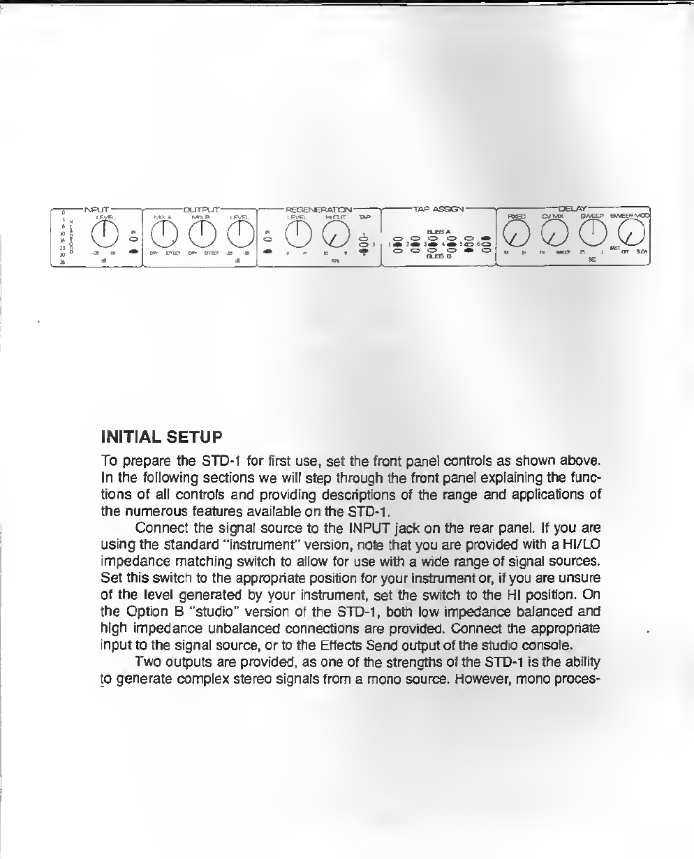
INITIAL SETUP
To prepare the STD-1 for fiist use, set the front panel con^ls as shown above.
In Vie foHowfng sectfons vie win step through the front panel explaining the func-
tions of all controls and prayiding descriptions of the rsnge and appHcatkms of
the numerous features a^^Aable on the STD-i
.
Connect the signal source to the INPUT jade on the rear panel. If you are
using the standard "instnjment" version, note that you are provided with aHI/LO
impedance matching switch to allow for use with awide range of signal sources.
Settfifs switch to the appropriate position for your instnonent or, if you are unsure
of the level generated by your instrument, set the swtch to the HI position. On
the Option B"studio" version of the STD-1 ,both low impedance balanced and
Ngh impedance unbalanced connections are provided. Connect the appropriate
input to the signal source, or to the Effects Send output of the studio console.
T>ivo outputs are prDvidfad^ as one of the strengtfis of the STD-1 is the ability
to generate complex stereo sign^ from amono source. However, mono proces-

sing can still be accomplished tfiraugh the use of only one output channel, prefer-
ably OUTPUT A. Again, note that the "studio" version allows for either balanced
or unbalanced connections. In an instnjmental setup, the most versatile output
connection would tie driving two amplifiers separated by enough distance to
create the stereo motion or ambience effigy. Using atwo cJrannel amplifier
(such as aguitar amp with a'nomial' and a'reverb' channel) can still create
some interesting eftects by setting each channel for difterent tone and effects
levels. However, most effects will be more gra^ through the use of astereo
reproduction system. In astudio environment the output connections become
slightly more complicated depending on inpute available on your console, the
effects you are creaHng, and many other factors. If you are using the Effects
Send system as outlined above, you will need to work out an alternative for rout-
ing back into the console as true stereo. Most semi-pro consoles will only have a
mono Effects Return input If this is your case, try returning the STD-1 outputs to
the AUX INPUTS, Most Auxilaiy Inputs have tevel conbols whh^ are useful as
effects return levels.
If your AUX INS are not available, look for direct BUSS INPUTS for the
submix or output mix stages. If no such source is provided for astereo effects
return, you may be required to use two of the input channels as \he return. In this
last case, be sure to have all effects and monitor sends at minimum (at least untH
you become familiar with the operation of the STD-1), and the pan controls at
opposite extremes. One additional note to studio users —be sure to check the
OUTPUT corrtrols for MIX Aand MIX B. In the majority of cases, the original dry
signal will be routed to the output mix through internal routing. To avoid exces-
sive dry signal level, lack of effect depth, or bluning of stereo image, the OUT-
PUT MIX controls should be set fully towards EFFECT.
With inputs and outputs properly terminated, apply power to the unit by
connecting to agrounded outlet and selecting the ON position of the rear panel
power switeh. The power indicator LED at the right of the front panel should now
be en. If not, check your power source and the rear panel fuse.
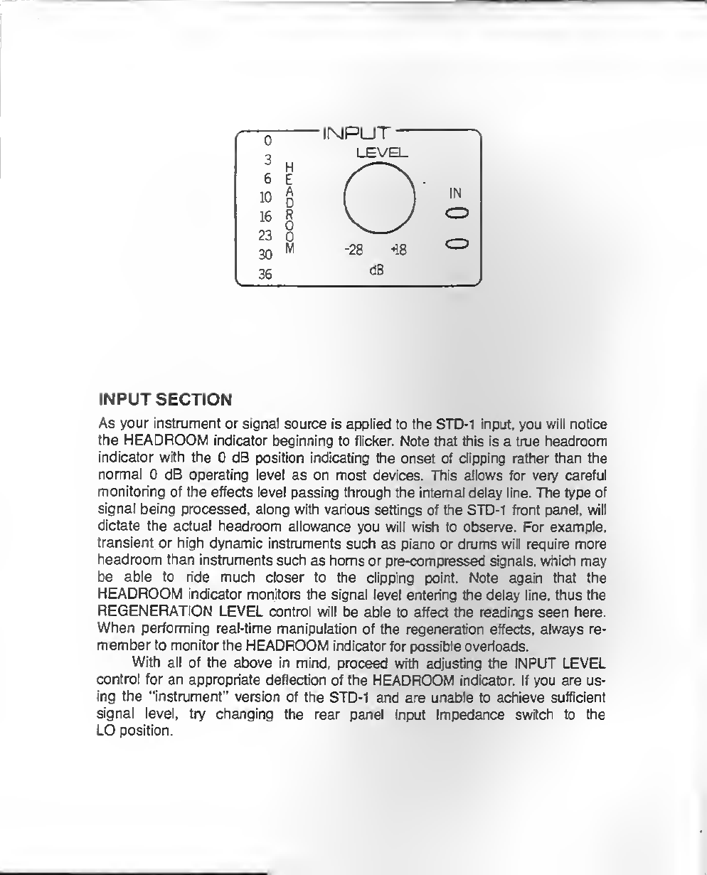
INPUTSECnON
As your instrument or signal source is applied to the STD-1 input, you will notice
the HEADROOM indicator beginning to flid«r. Note that this is atrue headroom
indicator wttti the 0dB position indicating the onset of dipping rather than me
nonnal 0dB operating level as on most devices. This allows for very careful
monitoring of the effects level passing through the internal delay line. The type of
signal l>^ng processed, along with various settings of the STD-i front panel, will
dictate the actual headroom allowance you will wish tt> observe. For example,
transient or high dynamic instruments such as piano or drums will require more
headroom than instruments such as homs or pre-compressed si^ials, which may
be able to ride much closer to the clipping point. Note again that the
HEADROOM indicator monitors the signal level entering the delay line, thus the
REGENERATION LEVEL control will be able to affect the readings seen here.
When performing real-time manipulation of the regeneration effects, always re-
member to monitor the HEADROOM indicator for possible overloads.
With all of me above in mind, proceed with adjusting the INPUT LEVEL
control for an appropriate deflection of the HEADROOM indicator. If you are us-
ing the "instalment" version of the STD-1 and are unable to achieve sufficient
signal level, by changing the rear panel Input Impedance switdi to flie
LO position.

1
I
OUTPUT
MIX AMIX BLEVB-
DRY EFFECT DRY FFECT -28 *18
dB
OUTPUTSECTION
At this point you should be getting sound through your STD-I. Uft the Effect
IN/OUT swrtch located in the INPUT section. Your source ^gnal should sound
noticeably fuller.. .more specifically you should be hearing slapback echo. Note
that each of the two outputs has its own Tap Assignment buss, and here in the
Output Section the MIX Aand MIX Bcontrols each allow mixing the respective
Tap Assignment buss with any blend of the dry input signal. Users of the "instru-
ment" version will most commonly be mixing dry and effects signals in the center
range of these controls. Studio users will find the unit most useful wntti the MIX
controls fully towards Effect, so the processed signal can be lennxed manually
witfi the console Effects Rtium system.
The adjacent EFFECT LEVEL control provides capabilrtres for balancing the
overall level (both channels simultaneously) of the Effect against the adjusted
Input level. "Riis avoids overpowering effects levels when using footswitch or re-
mote systems, aswell as adjusting for Effects Return levels required by various
consoles.
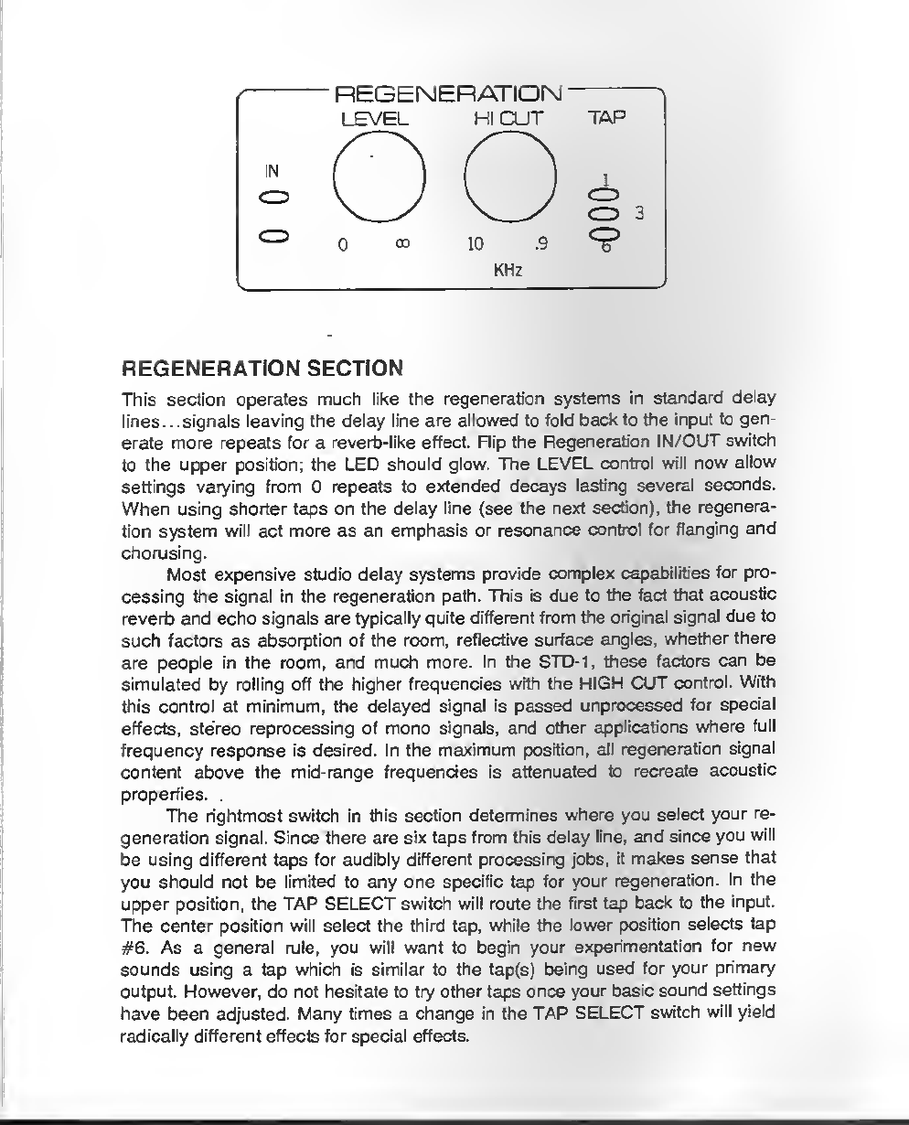
REGENERATION SECTION
This section operates much like the regeneration systems in standard delay
Itn^.. .signals leaving the delay line are allowed to fold back to the input to gen-
erate more repeats for arevertj-like effect Rip the Regeneration IN/OUT switch
to the upper position; the l^D ^wuld ^ow. The LEVEL control will now allow
settings varying from 0repeats to extended decays lasting several seconds.
When using shorter taps on the delay line (see the next section), the regenera-
tion system will act more as an emphasis or resonance control for flanging and
chorusing.
Most expensive studio delay systems provide complex capabilities for pro-
cessing the signal in the regeneration path. This is due to the fact that acoustic
reverb and echo signals are typically quite different from the original signal due to
such factors as absorption of the n^om, reflective surface angles, whether there
are people in the room, and much more. In the STD-1, these factors can be
simulated by rolling off the higher frequencies with the HIGH CUT control. With
this control at minimum, the delayed signal is passed unptocessed for special
effects, stereo reprocessing of mono signals, and other appBcations where full
frequency response is desired. In the maximum position, all regeneration signal
content above the mid-fange frequendes is attenuated to recreate acoustic
properties.
TTie rightmost switch in this section determines where you select your re-
generation signal. Since tha« are six taps from this delay line, and since you will
be using dfffereiiHafK tor iaiidtbly different processing jobs, it makes sense that
you should not be limited to any one specific lap for your regeneration. In the
upper, position, the TAP SELECT switch will route the first tap back to the input.
The center petition wfli select the third tap, while 9te lower position sheets tap
#6. As ageneral rule, you will want to begin your experimentation for new
sounds using atap which is similar to the tap(s) being used tor your primary
output. However, do not hesitate to try other taps once your basic sound settings
have been adjusted. Many times achange in ttie TAP SELECT switeh will yield
radically different effects for special effects.
TAP ASSIGN
BUSS A
CD CD 0cz) cr> C3
1CD 2CD 3CD 4CD 5CD 6CD
C3 QCD Cr> C3 CD
BUSS B
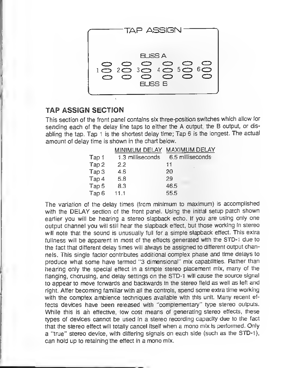
TAP ASSIGN SECTION
This section of the front panel contains six three-position switches which allow for
sendhig eat^ of the delay Hns to either the Aoutput the Boutput, or dis-
abling the tap. Tap 1is the shortest delay time; Tap 6Is the lot^iesL The actual
amount of delay time is shown in the chart below.
The variation of the delay times (from minimum to maximum) is-accomplished
with the DEl_AY section of the front panel. Using the initial setup patch shown
earlier you will be hearing astereo slapback echo. If you are using only one
output chvmel you will stUI hearthe slapback effect, but tho^ working in stereo
will note that the sound is unusually full for asimple slapback effect. This extra
fullness will be appeirent in most of the effects generated with the STD-1 due to
the ^ct that diflerent delay times WHI always be assigned to different'oulputchan-
nels. This single factor contributes additional complex phase and time delays to
produce what some have termed "3 dimensional" mix capabilities. Rather than
hearing only the spedal effect 4n asimple stereo placement miXi rnany of ttie
flanging, chorusing, and delay settings on the STD-1 will cause the source signal
to appear to move fonwards and backwards in the stereo field as well as left and
right After becoming fomilja- wNh^all ttie controls, spend someodra time working
with the complex ambience techniques available with this unit. Many recent ef-
fects devices have been released with "complementary" type stereo outputs.
While this fs ah-effiective, kiw cost means of generating stereo effects, these
types of devices cannot be used in astereo recording capacity due to the fact
that the stereo effect will totally cancel itself when amono mix is perfomied. Only
a"true" stereo devk», vnth differing signals on each side (such as ttie STD-1).
can hoM up to r^ning ttie ^fect ki amono mbc
Tap 1
Tap 2
Tap 3
Tap 4
Tap 5
Tape
MINIMUM DEU\Y MAXiiv^UM DELAY
1.3 mUNseconds 6.5 millisecpnds-
Z£ 11
4.6 20
5.8 29
8.3 46.5
11.1 55.5

DELAY )
HXED CV MIX SWEEP SWEEP MOD
DELAYSECnON
The controls located here are actually delay modulation or control seRings. You
will probably make more setting adjustments in this section than elsevirtwre on
the front panel. This is where most patches will be "fine tuned."
VvB FIXED control allows for setting the initial static delay time of the STD-
1. Using the standard initial setup patch once again you will hear the slapback
echo sound. To more accurately define wh^ you are hearing, return to the Tap
Delay Time diart in 4ie previous section. The times listed for Taps 5and 6at
maximum delay are 46.5 mS and 55.5 mS respectively. This is what you are
hearing. Note that when the FIXED control is set to the 5X extreme, you will
achieve maximum delay from each tap. Advance this control to maximum and
notice that the echo gets shorter. Using the Tap Delay chart, look up the
minimum delay times which you are now hearing.
The CV MIX control allows you to fade between the static setting of the
FIXED control and the sweeping voltage of the internal tow frequency oscillator.
Retum the FIXED control to the 5X posilion and note that you hear no automatic
sweeping or modulatton of the "echo" times. As the CV MIX control is advanced
to mid-position, you will hear an increasing amount of automatic sweeping (prob-
ably manifesting itself as massive pitch detuning). One of the reasons the pitch
alteration is so great is because we are at along delay setting. While CV MIX is
at mid-position, the RXED control mil still have an effect on ttie delay time set-
ting. So, turn ttie FI3CB3 contfcrf up tb the 1X setting. The piteh sweeps should be
less severe, but sMI happenir*; Advancing the CV MIX control all the way1o
SWEEP will restore ahigher level of detuning, but notice that the FIXED control
now no effect. Thus, the CV MIX control acts as apanning control to select
either the FIXED control, the SWEEP oscillator, or any blend of the two.
With the sweeping still occuring, adjust the SWEEP control and note th^ an
extremefy wide range of sweep effects are av^lable. The ^dremely slow sweeps
will be useful for chorusing, flanging, and subtle effects; faster sweeps'can pro-
duce Vibrato, fast flanging or rotating speaker simulation.
Set the CV MIX for full sweeping effects, and adjust the SWEEP speed
towards minimum for aslow but audible sweep. For this particular experiment, it
may be helpful to enable the regeneration section with the regeneration LEVEL
near maximum. This wHI allow you to more audibly hear tfie delay time changes
we are about to discuss. Slowly begin advancing the SWEEP MOD control and
listen for the point where the delayed signal begins "trembling." Note that the
master sweep contfriues to skwiy modulate ttie delay, but the au)dliaty Sweep
Mod oscillator now superimposes ahigher frequency sweep onto the master
sweep pattern. Continue advancing the SWEEP MOD control and note that the
frequency of the liembling" gets slower. The discerning listener mil also hear
that the slower sweep mod frequencies affect the delay time in greater amounts.
The circuitry of the STD-1 automatically compensates for the typically large pitch
shifte ttiat occur when faster sweep frequendes are used. The result is acom-
plex sweep modulation circuit which does nol significantly alter the musical use-
fulness of apatch when engaged or altered during aperformance or mix. There
are many interesting effects which can be achieved with this contnal which simply
cannot be obtained with standard LFO designs, such as vibrato at the same time
you are doing aslow flange. By setting the master LFO and the Sweep Mod
circuit to enharmonic speed ratios, apseudorandom sweep pattern can be set
up. By taking this pseudorandom sweep, attenuating it by placing the CV MIX
around S5%, turning tiie FIXED delay setting to approximately 3X to 5X, and
selecting several TAF^ in astereo assignment you can achieve an extremely
thicit chorus sound.
At this point, you should suffidentiy understand the panel operations of the
STD-1 to begin experimenting with the patches shown in the rear of this manual.
Note that the patches given are approximate. Don't tie aftaid to experiment or
fine tune the patches to your taste. There are many moiBS^tBr^s fromlhfs unit
than we could even begin to cover. Be sure to mark your favorite settings on the
blank charts provided in this manual. If you wish to share your favorite settings
with others, please send copies of your settings to A/D^ for use in future
releases of this manual.
EXTERNAL CONTROL
Four jacks are provided on the rear panel of the STD-1 to allow:«ctemal confrol
during live performance, or- as. rpmote operation in astudio. Tliese jaci<s also
provfde capabilities for more comply control stmctures than are available from
the intemaJ circuitry alone.
The FOOTSWITCH jack is astereo connector designed to accept standard
dual footswitches, such as those used with guitar amps. For those building
custom installations, the "tip" must be shorted to ground (the connector "shaft")
to enable the master Effect In/Out. Note that the front panel switch may still be
used when the footswitch is connected, however the panel switch must be in the
OFF position to allow operation of the remote. The "ring" of the connector is
shorted to ground to switch the Regeneration in and out. The regeneration foot-
switch interacts with the front panel switch as described for the effect footswitch.
In emergency situations, single footswitches with mono connectors may be used,
but the Regeneration will always be ON, and the front panel Regoieration
1_EVEL must be used to fade the regeneration in and out.
The remaining three \acMs are used for control voltage interfadng, using the
Standard 0to +5 volt control range available from most pedals and synthesis
equipment Both CV IN jacks have provisions for internally generating a+5 volt
level which"ram setf-powe*" standard footpedals. The levels of voltage avalable at
the connector are shown below. To use astandard A/DA CONTROL PEDAL A,
use the three conductor cable provided with the pedal. For custom inst^lations,
apply the external control voltage between the "ring" and the "shaft," with the
shaft being ground and the ring being the positive voltage. No connection need
be made to the "tip" for this application. For applications where no remote power
is pttjvided, acontrbt can be wired across me tip voltege as shown below, with
the wiper of the control returning to the "ring" at point 2. In emergency setups,
standard "volume control" pedals may be used by obtaining astereo splitter cord
adapter which has astereo plug on one erKl and two mono jacks at the other.
The jack carrying the +5 volts mates with the cord running to the "Instnjment In"
of the pedal. The ring connection return jack is fed to the "Amp Out" of the pedal.
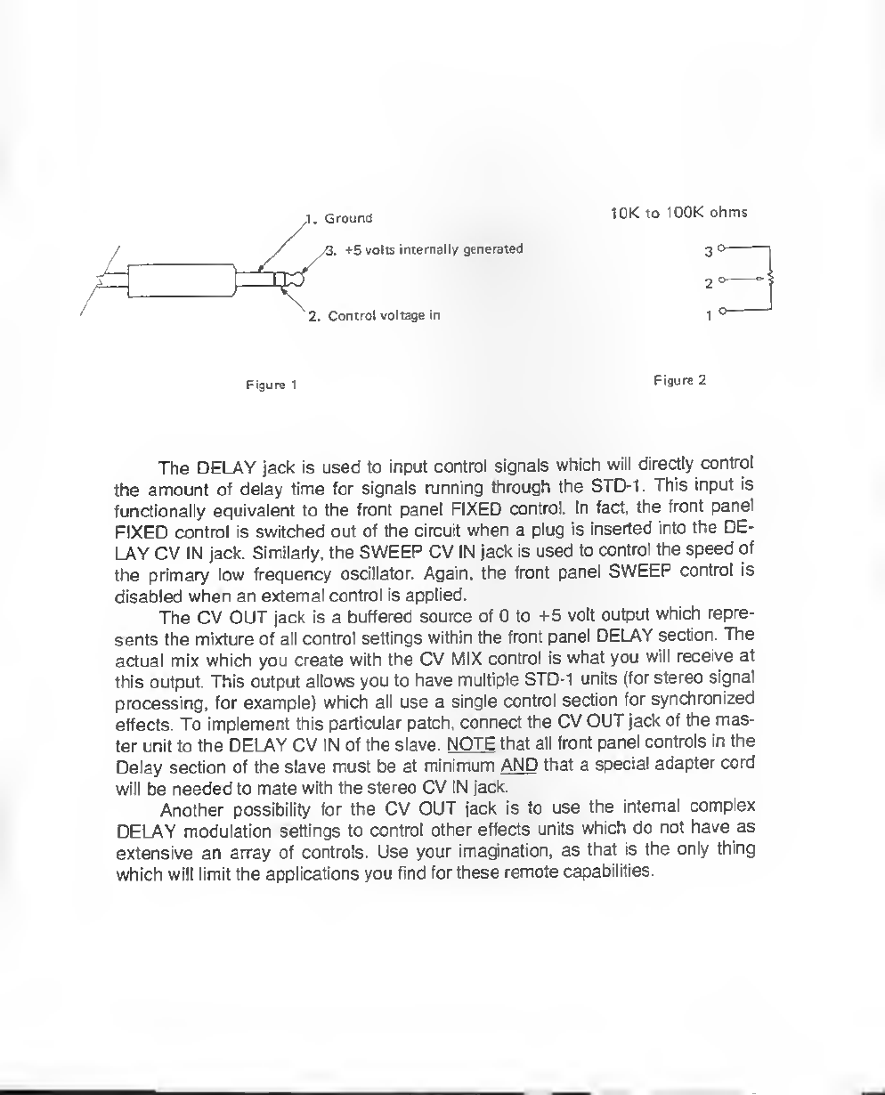
.Ground
4Svi>lis{nijBro8lly generated
7. Control voltage in
Figtiml Figure 2
The DELAY jack is used to input control signals which will directly control
the amount of delay time for signals njnning through the STD-1 .This input is
funcHonally equiv^ent to the frwit pan^ FIXED control. In fact, the front panel
FIXED control is switched out of the circuit when aplug is inserted into the DE-
LAY CV IN jack. Similarly, the SWEEP CV IN jack is used to control the speed of
the primary kw frequency oscMator. Again, the front panel SWEEP contfrt is
disabled when an external contnDl is applied.
The CV OUT jack is abuffered source of 0to +5 voit output which repre-
sents the mixture of all confinol settlngswithin flie ftont paiel DELAY section. The
actual mix which you create with the CV MIX control is what you will receive at
this output. This output aJlows you to have multiple STD-1 units (for stereo signal
processing, for example) whi* all tise asingle control section for synchronized
effects. To implement this particular patch, conned the CV OUT jack of the mas-
ter unit to the DELAY CV IN of the slave. NOTE that all front panel controls in the
Delay section of the slave must be minimum AND that aspecial adapter cord
will be needed to mate with the stereo CV IN jack.
Another possibility for the CV OUT jack is lo use the internal complex
DELAY modulation setHngs to control other effects units which do not have as
extensive an array of controls Use your imagination, as that is the only thing
which will limit the applications you find for these remote capabilities.

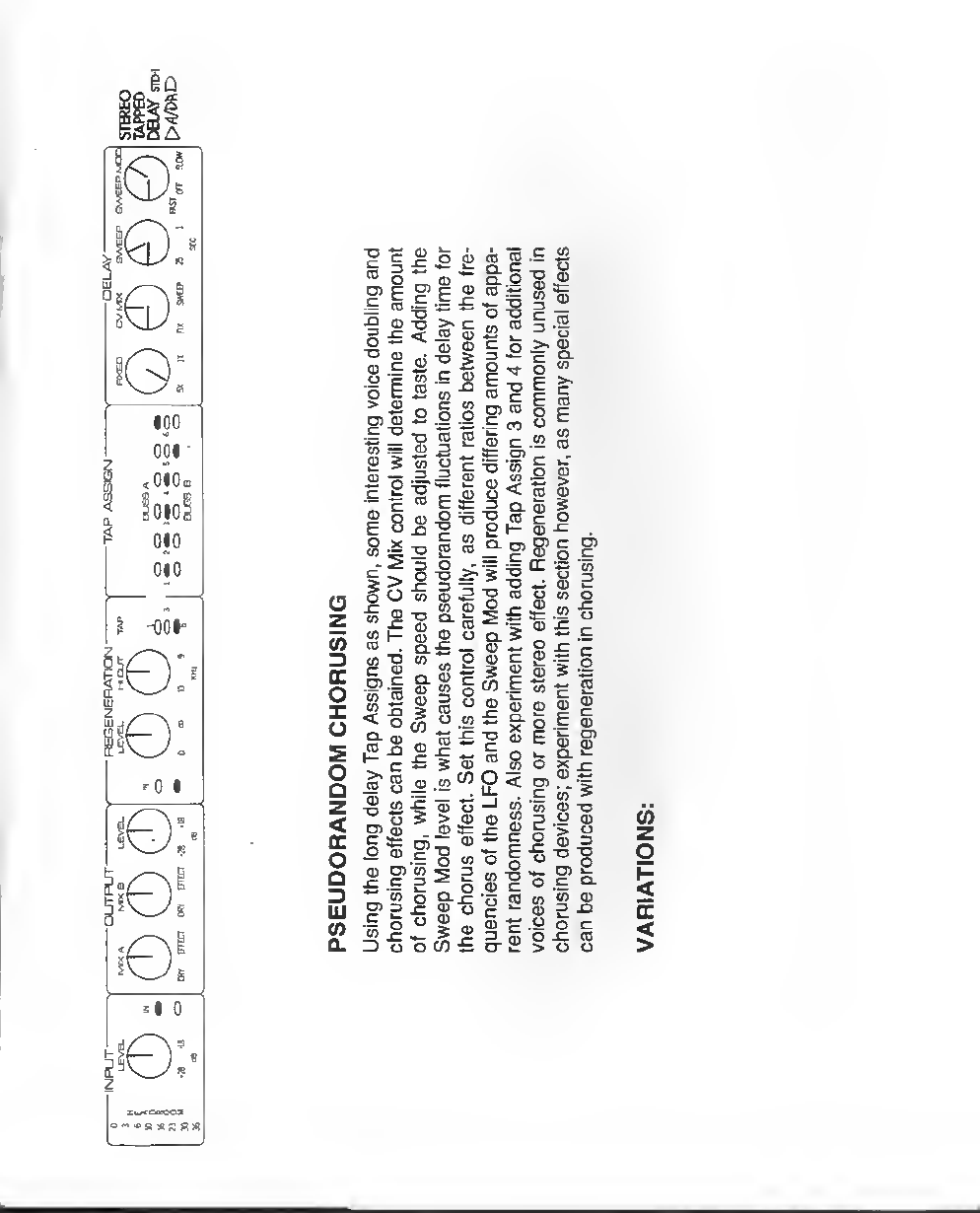
Of
G:
010
<0I0.;
001
100
I^oc^'
3"=
1
i| 0
tO:
10!
i| 0
iQ=
•5 ^-
z
<
_J
IL
o
oc
lU
U0) (O
5 " -- o
^oo- "
<D *^ >- (U
f= .ou.
I
§|b
^=3«
i«"."K
CO
To
(0
u
p
(0 £
01 -n
^1
rat
Io
CI- £
X3
ui To
H
E§
(0 u
m=
£^ 1
>
c
S_
—(D
ra
0)
S-i -D
CO CO
8i3
0) o_P
Oj-P to

PI
iG!
001
<OIO.li
010
010
M0
e:
<l 0

^"5
-OIC
i| 0
1=
S o
a.
1
cn tr
g(0
EQj
.b m.i=
(D CD
1^
IS
o
Z
C5
Z
<
-J
L.
5SPc
Z
u
I-
z
ci2
E^
"21
S0)
ss.
Si ?
ID ^CO
c-2
e- TO Q-
™"s
>«c
s-*
o«'3
c
ID O
CD cn
1=^
.>•
«3.
ID "
§2
so>
|i
d" *" .2
m
(0
o
X
QT3
I— c
CO nj
£(0
~c
^o
=CO
5£
o^
to o>
N
II
Ie
"I s
ID CO
CD
2^
CO
<l) «ffl
_1 PO
(0
DC
5
>l 0
>""OH RBa
0
'0 I
a
c
n
oi
c
•8
u
>E
o
z
CO
o
X
o
E
o
o
z
<
o
o
UJ
(/}
Q.
£
o
(0
c
i
CO
01
(0
(0
c
en
in
<
Q.
>-
m
D
D
O)
c
_o
<iS
oi -a
S«
Pg
ttj
33
Q.
a.
o
03
SS 1 I 5S-= "
^1
3O
So
Q. m
IS
II
ID in
3"O
u
9=
c
«
3
^
i2| g
03
OI
3u
tn
oQ-
t5 0)
"SCO
UQ.
—0)
2I
m£
£"a
©™
CO O
,u.
a) —
w o
o<u
II
1^
(0 3
S>.
*- C
tT O
_55
<^
o-J
(0 <J
£^
!o
g-o
»E
o•=
JO O
<O)
.c
S
W-J
oc:
c: O
?o
10
O.
oj
>.
C
m
E
i
<a
S
o
O£
U] O
II
ig
.i £
&g*
D. =
«s
U<])
>y
E°-
'm 0)
Otz
J= CO
CA
<
J0
e:

0)
<
DC
5
*l 0

A
*0 0
o;
UJ
S
<
S!2
Q. Z
(0
z
o
g
5
Table of contents


