Interface 75200 User manual

Interface Technology Group, Inc.
Model 75200
8 Channel CS-5259 Mu
Operation and Maintenance Manual
Manual Rev-
Interface Technology Group, Inc.
2107 South Hwy US-1
Rockledge, FL 32955
V 321-433-1165 F 321-433-0924

Specifications:
Power Input:…………………………. 90 – 265 VAC 47-470 Hz.
…………………………IEC Input connector 10W Nominal
Fuse:…………………………….…….1 Amp
Dimensions:………………….……… 19” Wide X 1.75” High (1 RU) X 10.25 Deep
Weight:……………………….……….4.75 Pounds
Operating Environment:…………… 32°
°°
° F to 100°
°°
° F, 0 – 95% RH Non condensing
Storage Environment………………..0°
°°
° F to 120°
°°
° F, 0 – 99% RH Non condensing
Signal Inputs:
8- Channels CS-5246 at 4800 baud. Trompeter type BJ-77 connector.
Signal Outputs:
2- CS-5259 individual buffered outputs (RS-422) on Trompeter type BJ-77
connector.
Remote Control ports:
Ethernet port:
A 10-100 Base T port for control and status.
RS-232 Port:
An RS-232 port is provided for control and status. Set up as: 9600-N-8-1
QUICK START INSTRUCTIONS
In order to get started quickly without reading the entire manual, a quick start lesson is
provided here.
With the 8- Channel CS5 59 Mux turned on, and power applied, connect one or more
CS-5 46 signals to the inputs. The two output connectors on the rear panel will output the
multiplexed signal. When a valid CS-5 46 signal is present, the associated LED will

change color from red to green. To program in a “tag” line, use the RS- 3 input, type
the word “status” to view all the current “tags”. To change a tag, type “channelx” where x
is the channel number you wish to change. Follow the prompts and type up to 16
alphanumeric characters followed by the enter key. The thumbwheel switch selects the
channel to be read on the LCD screen. The display mode button cycles through the
display options i.e. tag-event, tag-launch time, or event, launch time modes.
Overview:
The model #75 00 8 Channel Mux allows up to 8 channels of CS-5 46 to be multiplexed
together into a 38.4 KB stream for distribution. Along with the count data, each channel
is allocated 16 characters to be used as “tag” data. This tag data can be any alphanumeric
ASCII character string and is associated with a specific channel. Therefore, there are 16
X 8= 1 8 characters that are transported on the stream. The count data is sent in real time
with very little delay. The tag data is sent out as 4 bytes every 100ms. It can take up to
3. seconds for all channels in a reader to fully recover all 1 8 bytes. Since tag data is
designed to be used as labels, such as mission number or “local time”, and does not
change rapidly, it is not necessary for it to be sent at a high speed.
Having an 8 channel multiplexed signal allows users to have access to multiple counts at
their work places. It is not necessary to switch the data stream from a remote location.
Tags allow labels to be sent to all users at once and are usually set up before a mission.
See IRIG Standard 15-11 for a detailed description of CS-5 46 and CS-5 59.
Operation:
Connect a suitable AC mains power source to the rear IEC connector. Connect one or
more CS-5 46 signals to the desired input connectors. Turn on the AC power switch on
the rear panel.
The Model #75 00 will power up and begin sending out the multiplexed stream. If
desired, the “tag” data may be entered for each channel. See remote operation for
specifics on tag programming.
The thumbwheel selector switch selects which of the 8 channels is displayed on the two
line LCD screen. The actual multiplexed stream is decoded and displayed on the line
LCD and provides confidence that the actual data is in the stream.
The LCD screen will display the Tag, EC screen as a default on power up. Pressing the
Display Mode button will change the display to Tag, Launch Time. Pressing the button
again will display EC, LT. Further pressing of the button will start the sequence over
again.

Remote Control:
RS-232 Port:
Remote control of the Model #75 00 8 Channel Mux is accomplished through the
Ethernet port or via the RS- 3 port on the rear of the unit.
Connecting a computer running a terminal program such as Hyperterminal set up as
9600-N-8-1 allows control and status information to be passed from or to the multiplexer.
A standard straight through cable is required. Only pins ,3, and 5 are utilized.
Hitting Enter (C/R) will cause the Model #75 00 8 Channel Mux to respond with: CS-
5X8 MUX #XXXX> Where XXXX is the serial number of the unit.
Entering a keyword (see below for keyword definitions) followed by the enter key will
return either the status of the unit or begin an interactive dialog to make changes to one of
the two displays.
Ethernet Port:
The Ethernet port may be used in exactly the same way as the RS- 3 port by using a
Telnet program to connect to the IP address of the Model #75 00 8 Channel Mux. The IP
address of the port may be set to a fixed address or be dynamically set through DHCP.
The factory default is DHCP mode. The default telnet port is 10001. The default XPORT
control port is 9999.
The Ethernet port module is a Lantronix XPort module. It is recommended that the
Lantronix web site WWW.lantronix.com be consulted to understand how to use the
interface. A utility program from Lantronix called Device Installer (current version
4.1.0.9) should be downloaded and used to set up the IP address. This utility program
makes it easy to set up the parameters of the XPort device to customize it for the
particular network application.
Note that the XPort must be configured to provide a Modem Ctrl Out (DCD) signal on
configurable pin (CP) #1 (input, active low). This is necessary for the Model #75 00 8
Channel Mux to switch control ports from the RS- 3 to the ethernet port when a telnet
session is established.
KEYWORDS:
The following are keywords or words that are used by the Model #75 00 8 Channel Mux
to control the unit via remote commands. The keywords may be upper or lower case. The
words must be typed correctly. Incorrect typing or misunderstood words are returned as
typed followed by a question mark.
STATUS (C/R) Returns the contents of each channel’s tag data. Also returns the
firmware version.
CHANNEL (C/R) Returns “Current Identification for Channel #x: “ “ –then-
Enter up to 16 characters: . You may then type in up to 16 characters. Anything less than
16 will cause the remaining characters to be spaces. Anything more than 16 will truncate
the entry. The tag data is stored in EEPROM memory and remains intact when power is
off.
CHANNEL_ (C/R) Same as Channelx above.
Help (C/R) or ? (C/R) Returns with a list of available commands.
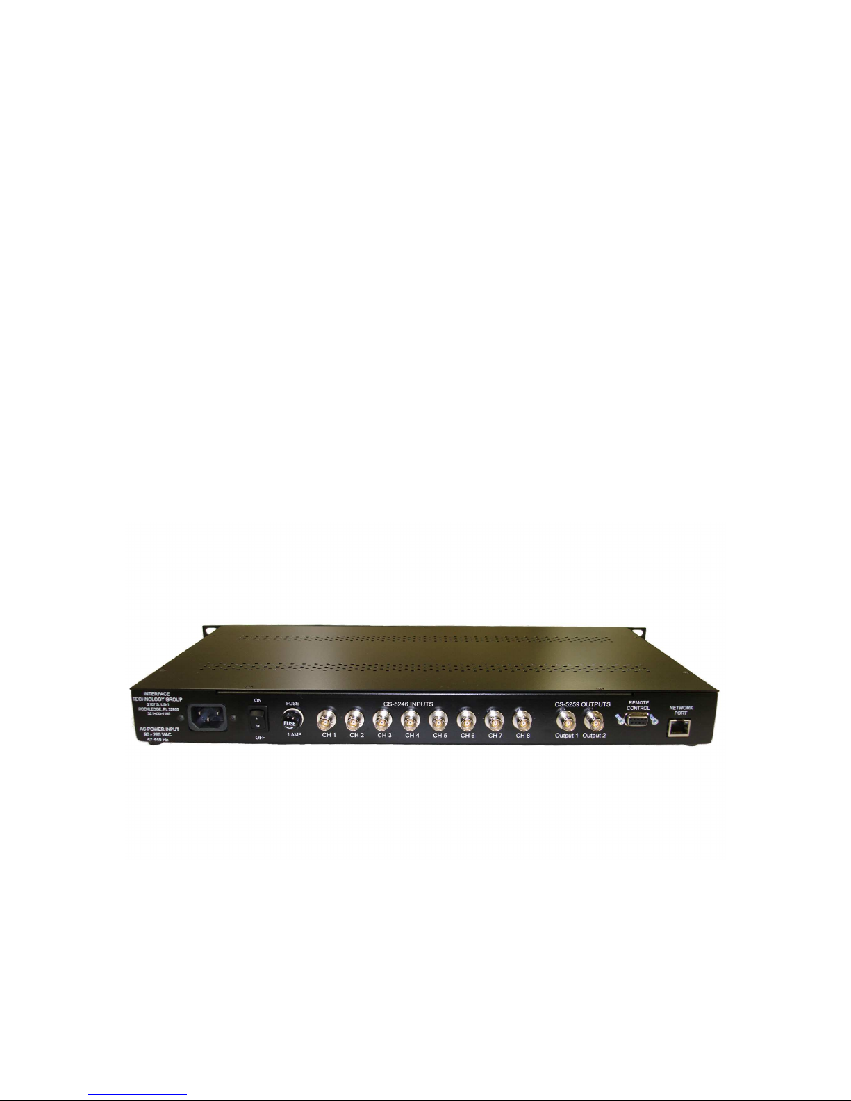
Rear Panel
Connections:
(8) Inputs CS-5259: (8) BJ-77 TWINAX connectors. Center pin= D+ , Ring D-
(2) Outputs CS-5259: (2) BJ-77 TWINAX connectors. Center pin= D+ , Ring D-

Control: DE-9 Female. RS- 3 Pin 5=GND, Pin =T, Pin 3=R.
AC INPUT: AC mains voltage is applied through the IEC connector.
90– 65 VAC 47-470 Hz.
NETWORK: RJ-45 Ethernet connector.
Power Supply:
The model #75 00 8 channel mux uses a “Universal Input” switching power supply for
cool and reliable operation. The power supply accepts any common voltage between 90
and 65 VAC or 100 to 370 Volts DC without any adjustment. A separate line filter is
built into the Model #75 00 8 Channel Mux for an additional measure of EMI
suppression. The Power supply used is UL listed and approved by several other agencies.
Routine Maintenance:
Remove dust from the cabinet when it accumulates. The front panel may cleaned with a
soft cotton cloth. Use only a small amount of mild soap and water solution to dampen the
cloth if necessary.
No routine checks or adjustments are required.
Table of contents


