A-M Systems 3
131 Business Park Loop, P.O. Box 850 Carlsborg, Wa 98324
Telophone: 800-426-1306 * 360-683-8300 * FAX: 360-683-3525
E-mail: amsys@a-msystems.com * Website: http://www.a-msystems.com
To accurately measure the impedance, verify at the OUTPUT connector that the signal
is a pure 1.0 kHz sine wave, and that the sine wave is at its maximum amplitude (the
point just before the signal becomes unstable).
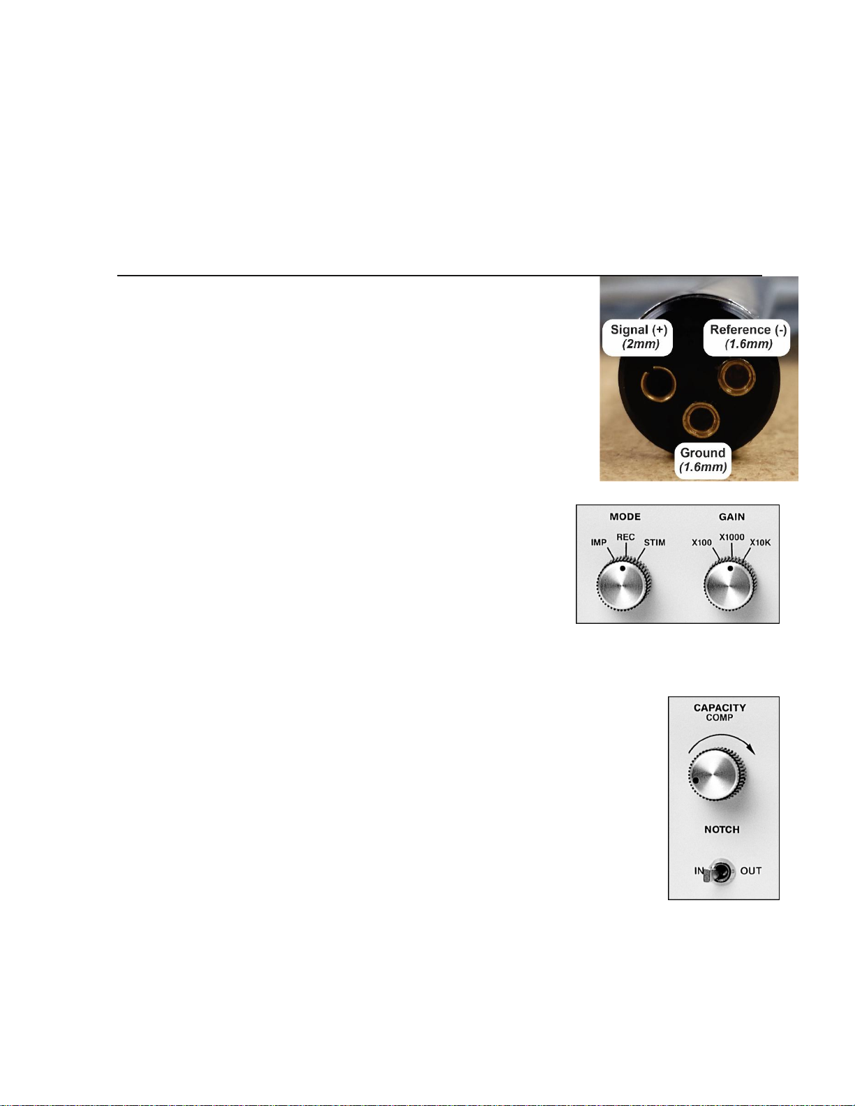
NOTCH: This switch allows the Notch Filter to be included (IN) in the signal processing
path or bypassed (OUT). Warning: Although the Notch Filter provided can
significantly reduce unwanted interference from the power source, it will cause some
distortion of the signal, especially in frequencies below 100 Hz. Therefore, the Notch
Filter should only be used if other noise reduction techniques such as proper
grounding and shielding are inadequate.
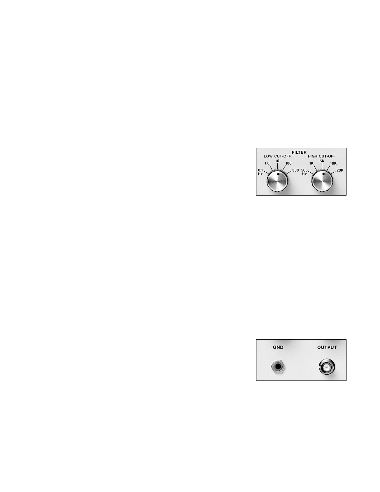
LOW CUT-OFF: This rotary switch enables the user to select the lower boundary
frequency at which point the channel’s input signal begins
to be cut-off. Signals below the cut-off frequency will be
attenuated by a factor of 100 (-40 dB) per decade decrease
in the input signal frequency. For example, if the LOW CUT-
OFF switch is set at 100 HZ, then a 10 Hz signal will be
attenuated by a factor of 100 while a 1 Hz signal will be
attenuated by a factor of 10,000.
The Low Cut-Off frequency should be selected based on the frequency content of the
signal to be recorded. One of the uses of this filter is to reduce slow variations or DC
levels in the input signal.
HIGH CUT-OFF: This rotary switch enables the user to select the upper boundary
frequency at which point the channel’s input signal begins to be cut-off. Signals above
the cut-off frequency will be attenuated by a factor of 100 (-40 dB) per decade
increase in the input signal frequency. For example, if the HIGH CUT-OFF switch is set
at 1 KHZ, then a 10 kHz signal will be attenuated by a factor of 100 while a 100 kHz
signal will be attenuated by a factor of 10 000. One of the uses of this filter is to
reduce high frequency noise that is above the frequency content of the signal being
recorded.
OUTPUT: This BNC connector provides the output signal from the amplifier channel.
GND: This connector on the front panel provides access to
the circuit ground for its channel. Either the PROBE GND
connector or the front panel GND must be connected for
proper operation. Usually the PROBE GND connector is tied
to the indifferent lead. If you desire to have the current constrained to a known path
you may want to place the GND elsewhere. Actual GND placement depends on the
application. For low-noise recordings a ground connection should be made in the
recording medium (i.e. bath ground, animal ground, etc.).