Pag. 1 di 26
INDEX
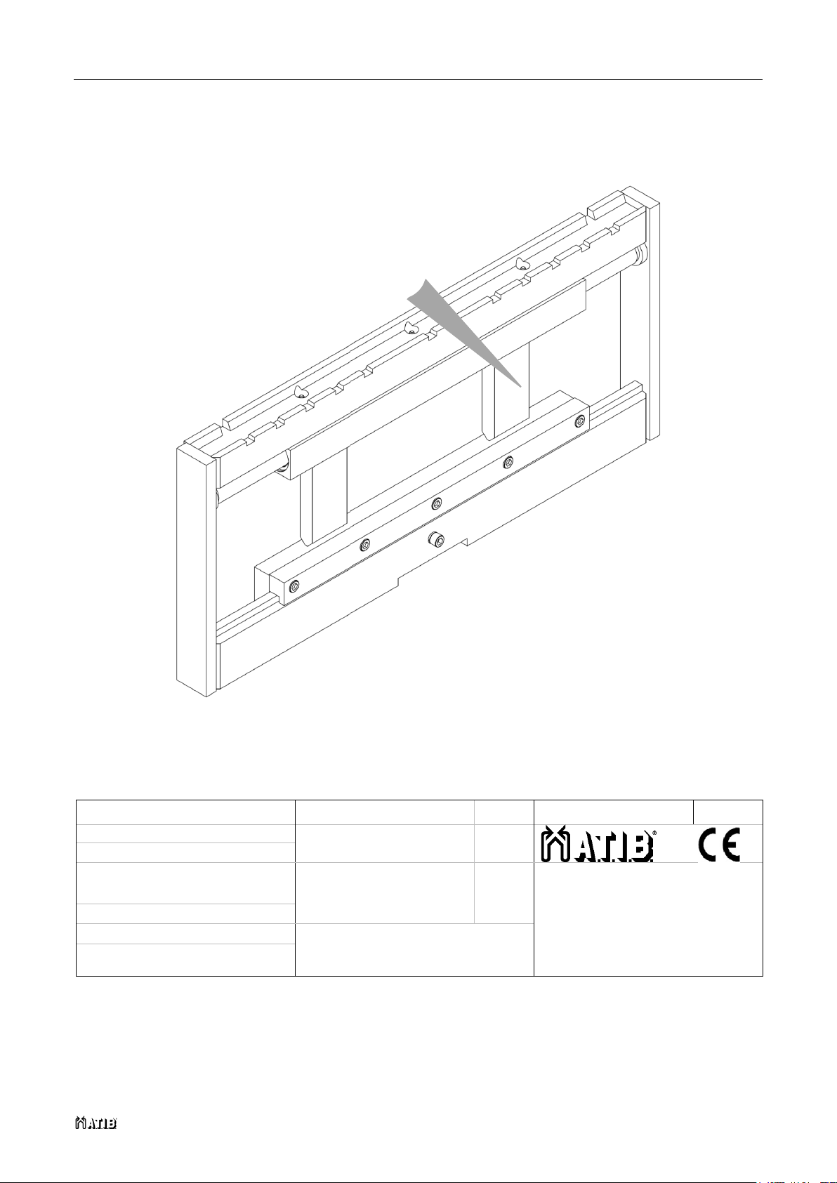
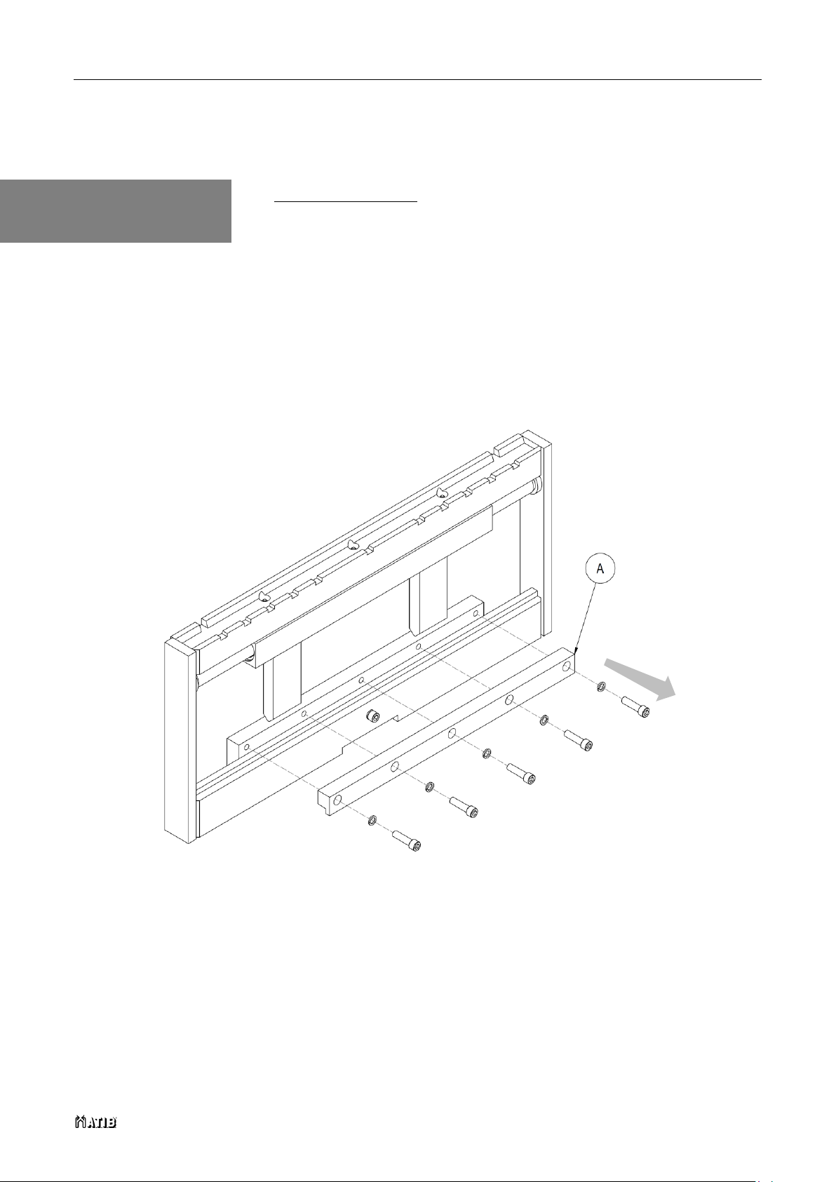
INTEGRAL SIDESHIFT TYPE 122
INDEX ......................................................................................................................................................1
1SAFETY RULES ...............................................................................................................................2
2INTRODUCTION ...............................................................................................................................3
2.1 Use and upkeep of this manual .........................................................................................3
2.2 Description of equipment...................................................................................................4
3INSTALLATION ................................................................................................................................8
3.1 Installation ...........................................................................................................................9
3.1.1 Installation the attachment without welded brackets................................................ 9
3.1.2 Installation the attachment with welded brackets ....................................................15
4USE RULES....................................................................................................................................17
5PERIODIC MAINTENANCE............................................................................................................20
5.1 Maintenance every 100 hours ..........................................................................................20
5.2 Maintenance every 300 hours ..........................................................................................20
5.3Maintenance every 1000 hours ........................................................................................21
5.4 Maintenance every 2000 hours ........................................................................................21
6DISASSEMBLY PROCEDURE.......................................................................................................22
6.1 Cylinder removal...............................................................................................................22
7BREAKDOWNS AND SOLUTIONS................................................................................................24
7.1 Breakdowns and solutions...............................................................................................24
7.2 Lubricate............................................................................................................................25