A&C GreenEnergy PowerMax+ 600 User manual

INSTALLATION MANUAL
400W OFF-GRID TURBINE

Features and Overview:
•Highly efficient Hybrid Solar/Wind Dual Output Capability to take
advantage of both solar energy and wind energy at the same time.
•With our electromagnetic speed limitation and blade over-speed braking,
no problematic mechanical furling is needed. The combination of
electromagnetic braking and aerodynamic braking maximizes energy
capture by extending PowerMax+ series turbine’s operating speed range
into the winds which are missed by the old-style wind turbines.
•Patented aerofoil blade design makes the system run much more
efficiently. The rotor blades are made with the latest advanced
thermoplastic engineering and precision injection-molding technology.
•Innovative maintenance-free design, featuring a system with only two
moving parts. The PowerMax+ series adopted an innovative over-speed
control so it improves the reliability by eliminating the moving parts for
mechanical over-speed protection and minimizing the moving parts to only
two.
•The blades have exceptional consistency and aerodynamic outline with a
mass distribution that ensures the rotors operate with nearly no noise and
minimal vibration.
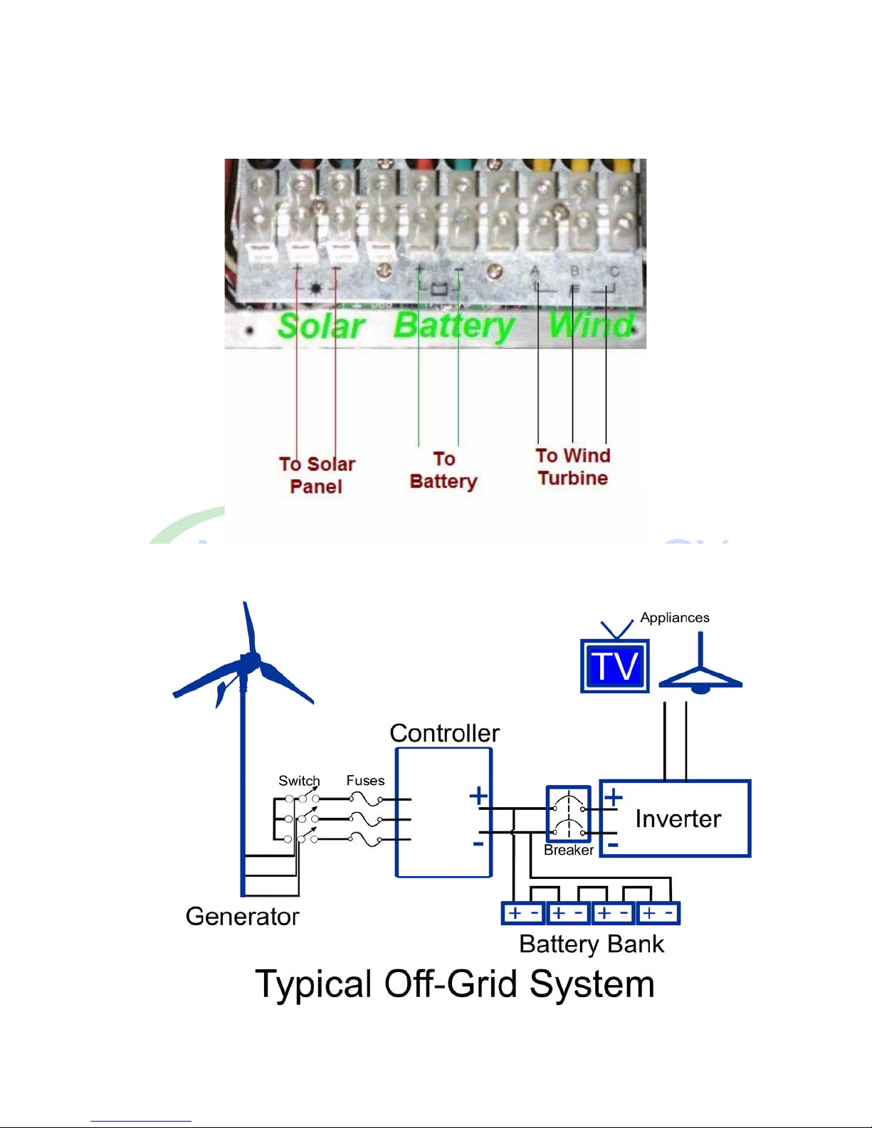
•Wind/Solar hybrid controller to work with both wind turbine and solar
panels.
•Low Start-up and cut-in speed; begins producing power at 5.2 mph., very
low startup/cut-in wind speed and a high coefficient of productivity and is
specially designed to prevent the blades from feathering post-stall.
•The generator is built using high-performance permanent magnets, so the
alternator is compact and light weight with a high power generating
efficiency.
•The unique winding and multi-pole design reduces the start-up torque of
the alternator that assures the PowerMax+ can generate electricity at the
lowest of wind speeds.
•Generator housing is made with precision-cast technology from high
strength aluminum to assure a high quality finish. It is designed for various
working conditions such as severe climates, sand and salt corrosive
environments and marine usage.
•Exquisite set with unmatched power generating performance. It is a great
green power source for the modern living environment.
•The system is easily installed; however, prior to installation it is important
that you thoroughly read this manual to ensure proper performance and
safety.

1. Package Contents:
Check the crate packaging. Call your PowerMax+ reseller to report any damage or missing parts.

2. Assembly
Assemble your PowerMax+ referring to following figures.
Note: Two versions of pole mounting bracket are available; the pole mounting bracket
in the package may be different from what is shown in above picture. We stock either
a Weld-on Ring Collar or bolt-on pole collar.
Part Number Description Quantity Usage
1 Generator Assembly 1
2 Rotor Blade 3
3 Rotor Hub 1
4 Front Cover 1
5 Front Cover Stopper 1 Fittings
6 Bolt M8*30 9
7 Flat washer M8 9
8 Nylock Nut M8 9
Rotor Blades
9 Bolt M6*35 1
10 Flat washer M6 1 Front Cover
11 Nut M16*1.5 1 Generator
12 Lock Washer M16 1 Assembly

2.1 Mounting to the Yaw Pole
Slide the yaw pole onto the yaw shaft of the head assembly and fastened by four
bolts M8/15 with flat washers and lock washers.
2.2 Mounting the Rotor Hub
1. Remove the nut, lock washer and flat washer from the alternator shaft;
2. Slide the rotor hub onto the alternator shaft and put on the flat washer and
lock washer;
3. Thread and tighten the nut. The nut should be tightened to 70-85 Nm.
2.3 Mounting the Rotor Blades
1. Blades should be in front of the rotor hub, with the flat side facing upwind.
2. Insert three bolts in the holes on the hub and blade. Place flat washers on
the end of the bolts, thread and tighten Nylock self-locking nut. Nuts
should be tightened to 8-12 Nm.
2.4 Attaching the Front Cover
Place the spinner over the center of the hub. Thread the M6*35bolt with the lock
washer and flat washer into the screw hole on the alternator shaft and tighten by
hex key (Allen wrench).
1. Drill through the tower tube to the electric wire
2. Attach the wind turbine head assembly

3. Assemble the wind turbine rotor hub
4. Attach the wind turbine rotor blades
5. Attach the wind turbine front cover
6. Secure the wind turbine screw cover

3 Site Selection:
Wind turbines should always be located as far away from trees, buildings, and
other obstructions as possible in order to minimize the effect of turbulence and
maximize exposure to the wind. Turbulence is a rapid change in wind speed and
direction caused by the wake from buildings and trees in the wind's path. It can
be damaging to wind machines over time.
Not only can buildings and trees cause turbulence, but they can also dramatically
reduce the energy available to a wind turbine. For optimum results, the turbine
should be placed at least 25-30 feet (8m) above any obstruction within 300 feet
(100m). Even if this means placing the turbine farther away from the load than
originally planned, the increased efficiency of your machine will more than make
up for any loss due to distance.
4. Tower Recommendations
Your tower-mounted PowerMax+ is designed to withstand a maximum horizontal
direction force of 500N. The tower must be capable of withstanding the wind
load. A guyed steel pipe tower is the most economical method to install a turbine.
The clamp-on pole connector fits 2 inch SCH 40 steel pipe which is widely
available in the US. Please contact us if you need help on this. The tower should
be electrically grounded properly.
Suitable Foundation:
The Construction Method for the tower base is according to the soil conditions at
your tower site.
•If the tower site is located on solid rock, it just needs to be leveled.

•If the tower site is located on the soft soil, you will need to have a tamped
area of no less than 30” diameter to prevent the foundation from shifting
and caving.
•If the tower site is located on the loose sand, dig a hole of 30” in diameter
and 5 feet deep. Fill the base with 2 feet of compressed rock or clay, tamp
that down, and add 2 feet of concrete. Once the concrete sets, fill the hole
with soil.
Construction Specification Layout of Tower for Wind Turbine-Guyed Tower
The tower base pad layout

Recommended Tower Specifications
PowerMax+ 400 PowerMax+ 600
Height of Tower Tower Diameter Tower Diameter Tower Wall
Thickness Radius of
Guy Wire
8 meters 80mm 100mm 3.5mm 4.6m
6 meters 60mm 80mm 3.4mm 4m
Dimension of Tower Base 800mm x 800mm x 200mm

5. Cable Wiring
The basic wiring diagram of single PowerMax+ system is as shown.

1. Controller Connection: Before erecting the PowerMax+ tower, connect the 3
Phase wire from PowerMax+ to the controller. These 3 wires can be connected to
the wind turbine terminals (A, B and C terminals) in any order. Turn the breaker
switch on the controller to the STOP position. After erecting your tower, make
sure that batteries are connected tightly and correctly to the controller, and then
turn the breaker switch to OPEN position.
2. The electric circuit breaker on the controller protects the batteries in case of
accidental shorts.
3. The battery capacity is subject to client’s requirement, but a 100-150AH/12V
battery is recommended for a single PowerMax+ System.
4. Undersized cables will cause energy loss (voltage drop) to the system. The
larger the cable size, the smaller the energy loss. However, larger size cables will
be more costly.
5. The negative pole of the battery should be properly grounded.
The following cable sizes are recommended for the PowerMax+ system:
Distance to Battery 50 meters 50-100 meters 100-150 meters
Cable Size 12 AWG(4mm2) 10 AWG
(6mm2) 8
AWG(10mm2)
6. Maintenance
The PowerMax+ is a very reliable series and is designed to run for long periods,
without any maintenance, under severe conditions. Routine checking of the tower
and cable wiring system is suggested to maintain the reliability and performance
of your PowerMax+.
1. Check guy rope tension and tighten/losen if needed, especially after storms.
During first three months after erecting the tower, periodic inspection should be
conducted.
2. Check all electrical connections to make sure they are properly connected,
tightened and free from corrosion.
3. Maintain batteries according to battery manual.
7. Safety Precautions
The PowerMax+ is designed with your personal safety as the first priority.
However, there are still some inherent dangers involved in operating any
electrical/mechanical equipment.
Safety must be your primary concern during the installation of the system.
7.1 Choose a calm day to erect the tower.
7.2 Undersized wires or bad connections should be avoided as they will often
result in overheating and potentially cause electrical fire.
7.3 Never approach an operating turbine during strong winds or during
thunderstorms.
This manual suits for next models
1
Table of contents
Other A&C GreenEnergy Wind Turbine manuals