Hivawt DS-700 User manual

1

2
Table of Contents
WARNING ....................................................................................................6
DISCLAIMER.................................................................................................8
1. Safety Precautions.................................................................................9
1.1 Mechanical Hazards .......................................................................10
1.2 Electrical Hazards ..........................................................................10
1.3 Assembly.......................................................................................11
1.4 Installation.....................................................................................12
1.5 Operation ......................................................................................13
2. Introduction........................................................................................14
2.1. DS-700 Specification ......................................................................15
2.2. DS-700 Standard Packing ...............................................................16
2.3. DS-700 Wind Power System Controllers ..........................................18
2.4. DS-700 Optional Parts ....................................................................19
3. Preparation of Assembly and Installation .............................................19
3.1 Selecting Location..........................................................................20
3.2 Mast Preparation............................................................................21
3.3 Foundation Guide for DS-700 .........................................................25
3.3.1 Ground Foundation ..................................................................26
3.3.2 Roof Foundation.......................................................................28
4. DS-700 Assembly and Installation........................................................31
4.1 Tools Required for Assembly and Installation .................................31
4.2 DS-700 VAWT Assembly .................................................................32
4.3 DS-700 Installation.........................................................................35
5. Wiring.................................................................................................40
5.1 General Information .......................................................................40

3
5.2 DS-700 Wire Size............................................................................40
5.3 DS-700 Wiring Diagram..................................................................41
5.4Grounding .....................................................................................44
5.5Fusing ...........................................................................................44
5.6Stop Switch....................................................................................44
6. Warranty .............................................................................................45
Table of Figures

4
Figure 2-1 General View of the DS-700 VAWT System ...................................14
Figure 2-2 DS-700 Standard Packing Contents ..............................................18
Figure 2-3 System Controllers.........................................................................19
Figure 3-1 Dimension for Mast .......................................................................23
Figure 3-2 Optional Mast Design ....................................................................25
Figure 3-3 Ground Foundation Construction Reference .................................27
Figure 3-4 Foundation for Roof Installation Reference ...................................29
Figure 4-1 Required Tools for Assembly and Installation...............................31
Figure 4-2 DS-700 Assembly Procedures - 1...................................................32
Figure 4-3 DS-700 Assembly Procedures –2 ..................................................34
Figure 4-4 DS-700 Assembly Procedures –3 ..................................................35
Figure 4-5 DS-700 Installation Procedures –1 ...............................................36
Figure 4-6 DS-700 Installation Procedures –2 ...............................................37
Figure 4-7 DS-700 Installation Procedures –3 ...............................................38
Figure 4-8 DS-700 Installation Procedures –4 ...............................................39
Figure 5-1 Wiring Diagram for Wind Energy MPPT Charger (WD481000).....43
Table Index

5
Table 2-1 DS-700 Technical Specification.......................................................15
Table 2-2 DS-700 Components........................................................................16
Table 5-1 Wire Sizing Reference .....................................................................41
Table 5-2 DS-700 Wiring Size Reference (WD481000) ...................................42

6
WARNING
THIS USER’ MANUAL PROVIDES INSTRUCTIONS AND GUIDELINES FOR
ASSISTANCE WITH ASSEMBLY AND INSTALLATION OF THE HI-VAWT’S DS-
700 VERTICAL AXIS WIND TURBINE. ALTHOUGH THE DS-700 VAWT HAS
BEEN DESIGNED AS EASY AS POSSIBLE FOR THE INSTALLATION, IT STILL
REQUIRES SPECIALIZED SKILLS, TOOLS AND EXPERIENCE AS WELL. FOR THE
PURPOSES OF ASSEMBLING, INSTALLING, OPERATING AND MAINTAINING
THE DS-700 VAWT, WE ASSUME THAT PERSONNEL WHO INVOLVED IN THE
WHOLE PROCESSES HAS THE SKILLS, TOOLS REQUIRED TO DO SO. NO ONE
SHOULD ATTEMPT TO ASSEMBLE, INSTALL, OPERATE AND MAINTAIN THE
DS-700 VAWT SYSTEM WITHOUT THE NECESSARY SKILLS, EXPERIENCE,
TOOLS AND SAFETY EQUIPMENT.
DISASSEMBLING THE PARTS FROM ORIGIONAL IS RESTRICTED. ALL PRE-
ASSEMBLED PARTS ARE FACTORY ADJUSTED, BALANCED AND TESTED. HI
VAWT TECHNOLOGY CORPORATION ASSUMES NO WARRANTIES AND
LIABILITIES OF DOING SO.
HI-VAWT TECHNOLOGY CORPORATION (Hi-VAWT) ASSUMES NO DIRECT OR
CONSEQUENTIAL LIABILITY IF FAULTY OR DANGEROUS ASSEMBLING,
INSTALLATION OR MAINTENANCE PRACTICES ARE PERFORMED. PLEASE
CONTACT HI-VAWT TECHNOLOGY CORPOATION IF CONSULTATION OR
ASSISTANCE IS REQUIRED.
HI-VAWT RECOMMENDS THE DS-700 VAWT SYSTEM SHOULD BE SITED
ACCORDINGLY IN AN EXCLUSION ZONE WITH CONTROLLING PUBLIC
ACCESS. APPROPRIATE WARNING SIGNS SHOULD BE PLACED ON THE
OPERATING SITE.
THE DS-700 SHOULD NOT BE INSTALLED NEAR UNPROTECTED POWER
LINES, TREES OR ANY OBJECTS THAT WOULD POSSIBLY CAUSE THE
HAZARDS OF THE OPERATION.


8
DISCLAIMER
Although Hi-VAWT recommends reading the entire manual thoroughly
prior to assembly and installation to ensure proper performance and
safety, this manual is intended as a guide only. It should not be
considered as a replacement of professional services or as a definitive
text for assembling and installing the DS-700 VAWT systems.
Hi-VAWT makes no warranties by either expressed or implied that the
information contained in the manual is accurate or complete. Hi-VAWT
Technology Corporation makes no warranties of fitness for a particular
purpose and /or site. Hi-VAWT will not be responsible for any direct or
consequential damages, or an incidental expense.
All instructions, figures and diagrams are believed to be accurate at the
time of printing. The success and safety in working with tools depend
greatly on individual accuracy, skill and caution. For this reason, Hi-VAWT
is not able to guarantee the result of any contained procedure in the
manual, nor can they assume responsibility for any damage to property or
injury to persons resulting from procedures contained in this manual.
Persons who engage in the procedures take their own responsibility and
risk.
Actual power resources and selected site conditions will highly affect the
energy production, which will vary with wind turbine maintenance,
surrounding environment, therefore, Hi-VAWT makes no representation or
warranties regarding energy production.
Wind generators, like other sources of electrical power, Must be installed
following the guidelines established by local and national regulations.
Please consult a local electrical contractor for details and regulations.

9
The information and all specifications contained within this manual are
subject to change without notice.
1.Safety Precautions
The DS-700 is designed with user safety in mind. However, there are
inherent dangers involved with any structural, mechanical and electrical
equipment, the surrounding environment as well.
Safety must be the primary concern as you plan the location, assembly,
installation and operation of the DS-700 VAWT. At all times be aware of
electrical, mechanical and rotor blade hazards.
This Owner’s Manual contains important instructions, guidelines and
safety notes that should be followed during the installation and
maintenance of the Hi-VAWT’s DS-700 VAWT.
Please read thoroughly and follow the instructions in this USER’S MANUAL
before assembling and installing the DS-700 VAWT.
Please refer to the following symbols which are used throughout this
manual to indicate potentially dangerous situations, important safety
instructions or important notes for you to know.
This WARNING symbol indicates a possible
dangerous condition.
Please use extreme caution when
processing the procedure.
This CAUTION symbol identifies an
improper operation that could result in
critical safety issue or damage to the
system controller or related devices.

10
The NOTE symbol describes an important
procedure or issue for you to know to
properly and safely operating the device.
1.1 Mechanical Hazards
Rotating blades present the most serious mechanical hazard. The
DS-700’s rotor blades are made of very strong anodized aluminum.
Some edge of the blades are sharp, please do not touch those
sharp blades. Even though, with the built-in airfoil, the edges of
those blades are not as sharp, they still will cause serious injury
when they start rotating, even at low speed.
NEVER TOUCH THE RUNNING ROTOR.
NEVER TRY TO STOP THE RUNNING ROTOR BY HAND.
DO NOT INSTALL THE DS-700 VAWT SYSTEM WHERE ANYONE
CAN APPROACH THE PATH OF THE BLADES.
AVOID ANY OBJECTS TOUCHING THE RUNNING ROTOR.
1.2 Electrical Hazards
The DS-700 VAWT System is equipped with sophisticated generator
and designed to provide protection from electrical dangers.
Heat in wiring systems is often a result of too much current flowing
through and undersized wire or through a bad connection. It is

11
important to follow the suggested wire-sizing chart to ensure a safe
electrical system
The battery, if applied, should never be short-circuited as it will
result a danger of setting the battery and cable on fire. In order to
avoid the threat and protect the cabling, fuses should be installed
in the lines connecting to the battery.
WIRING CABLE WITH INSUFFICIENTLY DIMENTION CROSS
SECTION CAN CAUSE ELECTRICAL FIRE.
NEVER SHORT-CIRCUIT THE BATTERY IF APPLIED.
1.3 Assembly
The DS-700 VAWT System is designed in “All Most Ready to Use”
format and shipped with factory pre-assembled packing. The only
assembly work required is Darrieus blades assembly. This user’s
manual will guide you through the assembly procedures with
detailed illustrations.
Please carefully read the assembly instructions in this manual
before proceeding.
It is important to have a suitable working environment for
performing the assembly tasks.
Refer to the suggested list of tools required for the assembly
and have all of them ready before proceeding.

12
PLEASE ALWAYS KEEP SAFETY IN MIND WHILE PERFORMING THE
ASSEMBLY PROCEDURES.
AWAYS WEAR SAFE HELMET AND GLOVES!
1.4 Installation
A fall from the height at which a wind turbine is ordinarily mounted
will often result in death or serious injury. Therefore whenever
practicably carry out as much work as possible on the wind turbine
at ground level. If it is necessary to work on the installation at such
height then use an appropriate access system such as a mast that is
designed to carry the load of a person; a man-rated winch or rope
access system; a hydraulic lift or other safe working platform. Wear
appropriate safety equipment and make the general working area
as tidy and safe as possible. Work during the daylight on windless
days. Above all else think carefully about what you need to do and
plan your work carefully, have all the tools and equipment ready
before your start.
Installation procedures should be performed as much as
possible at ground level.
Use safety harnesses, safe helmets, gloves, etc.
Make sure that all batteries, if applied, are disconnected from
the system throughout the installation process.
The DS-700 generator should be short-circuited to prevent
unintended wind turbine rotating during the shipment. Please

13
install the extension cable on the ground level and keep it short-
circuited throughout the installation process.
Please keep the rotor straight up or lie on the support stands at
all-time during the installation process to prevent the blades
twisted or lost balance.
Please perform the installation at a calm and windless day.
1.5 Operation
Please check the support structures, blades and electrical system
on regular basis.
Even though the rotor blades are very strong, however, if they
come in contact with a solid object, they can be damaged or
even broken.
When perform routine inspections, or at anytime you must
approach the path of the blades, please disconnect the power
leads from the batteries and short-circuit the wind turbine
output leads (use the Stop Switch after installation or tie the
output leads together) to stop the rotor blades from rotating.
The DS-700 is designed to be shut down through the use of stop
switch (brake switch).
NEVER APPROACH THE TURBINE DURING OPERATION.
14
2.Introduction
The DS-700 is a hybrid Vertical Axis Wind Turbine (VAWT) system which
combines drag-based design and lift-based design. It incorporates an S-
type of Savonius rotor and three airfoil blades of egg-beater shape
Darrieus to maximize the output performance.
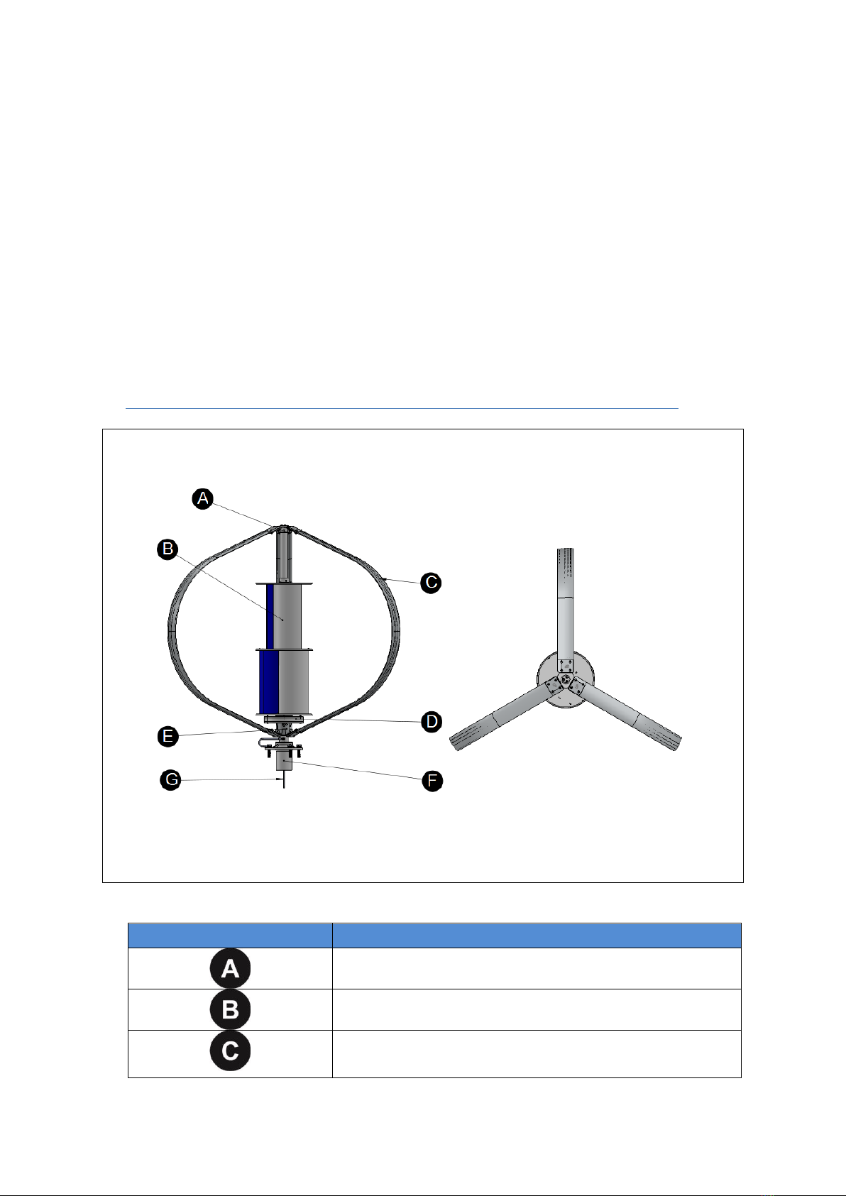
The following Figure 2-1 shows a general view and major components of
the DS-700 VAWT System.
Figure 2-1 General View of the DS-700 VAWT System
Parts
Description
Upper Darrieus Blades Connector.
S-Type Savonius.
3 Darrieus blades with built-in airfoil.

15
3-Phase, Direct Drive, Weather Sealed,
Mechanically Integrated Permanent Magnet
Generator.
Lower Darrieus Blades Connector.
Damper.
3-Phase R-S-T Generator Wires.
2.1. DS-700 Specification
The following table shows the technical specification of the DS-700
Wind Turbine.
Table 2-1 DS-700 Technical Specification
General Dimension
Rotor Diameter:
1,930 mm
Height:
Weight:
1,547 mm
52 Kgs
Blades
Number of Blade:
3
Blade Material:
Anodized Aluminum
Operation Mode
Cut-In Wind Speed:
<3 m/s
Cut-Out Wind Speed:
15 m/s
Survival Wind Speed:
60 m/s
Safety Mechanism
Over Speed Braking:
Yes. (Setup by Power Controller)
Manual Brake:
3-phase short-circuit Switch
Generator
Type:
AC, Direct Drive, Weather Sealed, 3-
Phase Synchronism PMG.
Rated Output:
700 W @ 12 m/s

16
Mounting
Foundation Mounting:
Min. Height above ground: 3 meters.
Roof Mounting:
Min. Height above roof: 2 meters.
Bedplate Mounting:
Used where deep excavation cannot be
applied
Warranty
Limited Warranty:
1 year on components.
2.2. DS-700 Standard Packing
Please check all components you receive from the shipment with
the packing list that comes with the purchase invoice or the
enclosed parts list in the shipment. Ensure that you receive all
standard components or parts for the DS-700 accordingly. If any
missing parts from the original packing, please contact Hi-VAWT
Technology Corporation for replacement.
Table 2-2 shows the standard packing of DS-700 VAWT System.
Please also refer to Figure 2-2 for part locations. Detail assembly
instructions will be discussed in the Chapter 4 - Assembly and
Installation.
Table 2-2 DS-700 Components
Labels
Description
Quantity Included
Anodized Aluminum Blade
(Assembly Needed)
3
Pre-assembled Components
1 Set
1
Upper Blades Connecting
Plate
1
2
S-Type Savonius
1

17
3
Vertical Axis
1
4
700W PM Generator
1
5
Lower Blades Connecting
Plate
1
6
R.S.T. Generator Wiring
Cables
3
7
Mast Connector with Damper
1
8
Wind Turbine Surge Wire
(Connected between Damper
and Flange of the Mast)
1
Bolt Sets
1
M10 x 30mm Button Hex
Head Bolts and Nuts (Set)
18
2
M8 x 30mm Button Hex
Head Bolts and Nuts
6
3
M20 x 60mm Hex Head
Bolts/Washers
8
7-1
Set Screw M10 x 10mm
2
7-2
Socket Countersunk Head Cap
Screw M8 x 16mm
2
8-1
M10 x 20mm Hexagon Socket
Head Bolt and Nut (Set)
1

18
Figure 2-2 DS-700 Standard Packing Contents
2.3. DS-700 Wind Power System Controllers
The standard wind energy MPPT charger is MAX-1000 for DS-700
VAWT off grid application. The descriptions and specifications of
MAX-1000 Controllers are detailed in user’s manual respectively.
Figure 2-3 shows the standard DS-700 Wind Power System
Controllers.

19
Figure 2-3 System Controllers
2.4. DS-700 Optional Parts
This DS-700 VAWT System is designed with simplicity in mind, so
there are just a few parts needed which all included in the standard
package. Concerning the shipping cost and different applications
applied by customers, the required mounting mast to setup the DS-
700 Wind Turbine is not included in the standard package. It would
be an optional part based on customer’s choice.
The detail description of the mounting mast will be explored in
Chapter 3.
3. Preparation of Assembly and Installation
Before going through the DS-700 VAWT System installation procedures,
please double check parts included in the package. Prepare all
required tools and equipments accordingly and have them ready on

20
hands. More importantly, all safety issues have been well thought and
followed.
3.1 Selecting Location
The DS-700 Wind Turbine is designed with flexibility to fulfill user’s
applications. It can be installed along the street, sea shore, on the
mountain, in the city, urban area, or just right on top of the roof of
the building. The major key factor of affecting the performance of
DS-700 Wind Turbine for all proposed applications is the location of
optimizing wind energy.
We assume that the proposed site of installing the DS-700 VAWT
System has been well evaluated by users themselves for
optimizing the wind energy environment before any installing
procedures performed.
DO NOT install the DS-700 VAWT System at a site where
anyone can easily approach the rotating blades.
DO NOT install the DS-700 VAWT System at a site surrounded
by obstructions. For example, Trees, power lines, etc.
DO NOT install the DS-700 VAWT System at a site with
improper structure to hold the DS-700 System.
Always follow your local regulations, codes about restrictions
applied to such system installation.
Table of contents


