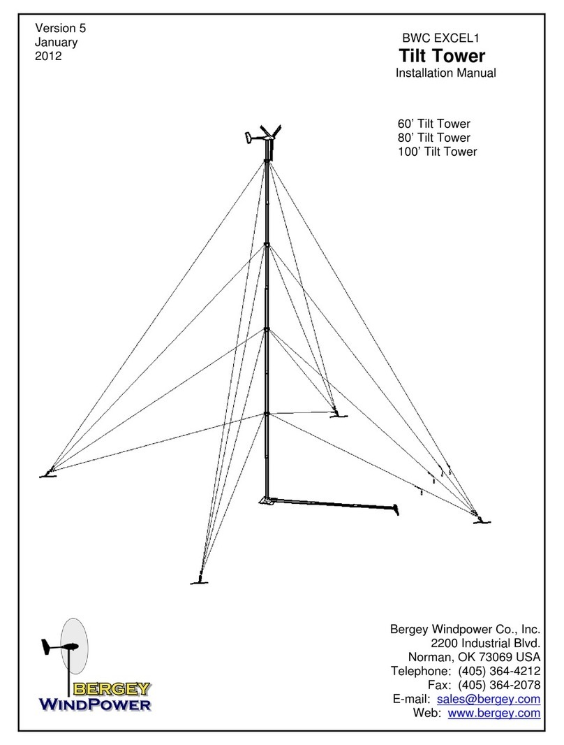
Bergey Powersync II User manual

Owner’s Manual
BWC EXCEL 10
Wind Turbine &
Powersync II
Grid-Intertie Inverter
Revision 2.0
April 2014
Part # MANXLS
Bergey Windpower Co.
2200 Industrial Blvd.
Norman, OK 73069 USA
TEL: 405-364-4212
FAX: 405-364-2078
E-mail: [email protected]
Web Site:www.bergey.com

Owner’s Manual BWC EXCEL 10 Turbine
Page 2
Contents
I. INTRODUCTION......................................................................................................4
II. EXCEL 10 SPECIFICATIONS .................................................................................5
III. SYSTEM DESCRIPTION......................................................................................6
A. ROTOR SYSTEM ..............................................................................................7
B. ALTERNATOR...................................................................................................7
C. MAINFRAME......................................................................................................7
D. SLIP-RINGS AND BRUSHES............................................................................7
E. TAIL ASSEMBLY AND AUTOFURL OPERATION ............................................7
F. SPINNER AND NACELLE .................................................................................8
G. Powersync II Inverter .........................................................................................8
IV. SYSTEM OPERATION..........................................................................................9
A. NORMAL OPERATION......................................................................................9
B. HIGH WINDS - AUTOFURL®..........................................................................10
C. UNLOADED OPERATION...............................................................................10
D. MANUAL FURLING .........................................................................................11
E. FURLING PROCEDURE .................................................................................11
V. POWERSYNC II INVERTER..................................................................................13
A. INVERTER SPECIFICATIONS........................................................................14
B. Other Specifications.........................................................................................14
C. Important Inverter Safety Instructions ..............................................................15
D. Installation........................................................................................................16
1. Dimensions...................................................................................................16
2. Locating........................................................................................................16
3. Mounting.......................................................................................................17
4. Electrical Connections ..................................................................................17
5. AC Output Connection..................................................................................18
6. AC Input Connection (Turbine) .....................................................................18
7. Earth Ground Connection.............................................................................18
8. Fuse replacement.........................................................................................19
9. Connection example.....................................................................................19
E. Inverter Operation............................................................................................20

Owner’s Manual BWC EXCEL 10 Turbine
Page 3
F. Touch Screen Display......................................................................................20
A. Inverter Fault Codes.........................................................................................22
VI. INSTALLATION...................................................................................................25
A. BWC EXCEL WIND TURBINE and TOWER....................................................25
B. FUSED DISCONNECT SWITCH.....................................................................25
C. WIRE RUN AND WIRE SIZES.........................................................................26
D. POWERSYNC II INVERTER............................................................................26
VII. INSPECTIONS AND MAINTENANCE.................................................................28
VIII. Trouble-Shooting Problems.................................................................................31

Owner’s Manual BWC EXCEL 10 Turbine
Page 4
I. INTRODUCTION
This manual contains important information concerning your Bergey EXCEL 10 wind
turbine system and its operational characteristics. We strongly recommend that you
read and familiarize yourself with its contents.
At several points in this manual items of special interest or significant impact are
highlighted by one of the following symbols:
DANGER: Hazards or unsafe practices that could cause personal
injury or death.
WARNING: Hazards or unsafe practices which could cause product
damage.
NOTE Significant points of interest.
Serial Numbers
Each Bergey EXCEL 10 wind turbine has a serial number located on the tower adapter.
The turbine serial number can also be found on the outside of the shipping crate and on
the warranty registration card. The blade serial numbers are located on the root pad
and also the shipping crate. We recommend that the serial number be copied to this
manual for possible future reference.
Bergey EXCEL 10 Serial No.: ________________________
Bergey EXCEL 10 BLADES Serial No.: ________________________
The Powersync II inverter has a serial number label on its right side. We recommend
that this serial number also be copied to this manual.
Powersync II Serial No.: __________________________

Owner’s Manual BWC EXCEL 10 Turbine
Page 5
II. EXCEL 10 SPECIFICATIONS
PERFORMANCE
START-UP WIND SPEED
5 mph (2.2 m/s)
CUT-IN WIND SPEED
5 mph (2.2 m/s)
RATED WIND SPEED
26 mph (11.6 m/s)
AWEA RATED POWER (at 11 m/s or 25 mph)
8.9 kW
AWEA ANNUAL ENERGY (at 5 m/s average
13,600 kWh
CUT-OUT WIND SPEED
none
FURLING WIND SPEED
36-40 mph (16-18 m/s)
MAXIMUM DESIGN WIND SPEED
134 mph (60m/s)
RATED POWER
10 kW
ROTOR SPEED
0-400 RPM
MECHANICAL
TYPE
3-Blade Upwind, Horizontal-Axis
ROTOR DIAMETER
23 ft. (7.0m)
WEIGHT
1020 lb. (460 kg)
GEARBOX
none
BLADE PITCH CONTROL
none
OVERSPEED PROTECTION
AUTOFURL®
TEMPERATURE RANGE
-40 to 140 deg. F (-40 to 60deg. C)
ELECTRICAL
OUTPUT FORM
240VAC, 1-Phase, 60Hz
GENERATOR
Permanent Magnet Alternator
POWER PROCESSOR
Powersync II Inverter
Power
Output
(AC kW)
Wind Speed (m/s) at Hub Height
0
1
2
3
4
5
6
7
8
9
10
11
12
13
14
0 1 2 3 4 5 6 7 8 9 10 11 12 13 14 15 16 17 18 19 20
Bergey Excel 10 Power Curve (Sea Level)
USDADataperIEC 61400-12
1 m/s = 2.237 mph

Owner’s Manual BWC EXCEL 10 Turbine
Page 6
III. SYSTEM DESCRIPTION
The Bergey EXCEL 10 is an upwind horizontal-axis wind turbine designed for
distributed generation applications, connected to the power grid on the customer’s side
of the utility meter. The complete unit consists of the following major components, as
shown in the figure below:
1. Spinner 6. Slip-ring and Brushes
2. PowerFlex® Blades 7. Tail Assembly
3. Alternator 8. Nacelle Assembly
4. Mainframe 9. Furling Winch
5. Yaw Bearing 10. Powersync II Inverter
Spinner Nacelle
Mainframe
Assembly
Tail
Assembly
Rotor
Blades
Alternator
Powersync II
Inverter

Owner’s Manual BWC EXCEL 10 Turbine
Page 7
A. ROTOR SYSTEM
The rotor system consists of three PowerFlex® fiberglass blades. Acting like aircraft
wings, the blades convert the energy of the wind into rotational forces that drive the
alternator. The PowerFlex® blades are rigidly attached to the alternator and they are
fixed pitch. The Excel 10 rotor blades have a proprietary airfoil, the BWC-7, which was
custom designed to provide high efficiency and low noise.
The blades for the EXCEL 10 are extremely strong because they are made in a
“pultrusion” process that puts more high-strength glass fibers in the structure than any
other molding technique. This contributes to their long life and toughness. Blade sets
are carefully matched for balance at the factory to ensure smooth operation of the wind
turbine. Each blade has a serial number inscribed on its root pad at the inboard end.
B. ALTERNATOR
The alternator converts the rotational energy of the rotor into electricity. The alternator
utilizes permanent magnets and has an inverted configuration in that the outside
housing rotates, while the internal windings are stationary. It was specifically designed
for the Bergey EXCEL 10 and produces power at low speeds, eliminating the need for a
speed-increasing gearbox. Since it uses permanent magnets, the alternator is
generating voltage whenever the rotor is turning.
DANGER The output wiring of the BWC EXCEL presents shock hazard
whenever the rotor is turning. Caution must be exercised at
all times to avoid electrical shock.
C. MAINFRAME
The mainframe is the structural backbone of the wind turbine. It serves as the
attachment point for the yaw bearing and the housing for the yaw-axis slip-ring brushes.
The yaw-axis is the full 360 degree pivot that allows the turbine to freely align itself to
the wind direction.
D. SLIP-RINGS AND BRUSHES
The slip-rings and brushes conduct the electricity generated in the alternator from the
moving (as it orients with the direction) wind turbine to the fixed tower wiring. The slip-
rings are enclosed in a metallic housing to help protect them from lightning.
E. TAIL ASSEMBLY AND AUTOFURL OPERATION

Owner’s Manual BWC EXCEL 10 Turbine
Page 8
The tail assembly keeps the rotor aligned into the wind at wind speeds below
approximately 35 miles per hour (16 m/s). At about 35 mph the AutoFurl® action turns
the rotor away from the wind to limit the rotor speed in high winds. The tail appears to
fold, but in reality the tail stays stationary as the rotor turns sideways to the wind. The
rotor furls to a maximum angle of 75 degrees (limited by rubber tail stops), so that the
unit continues to produce power in high winds. When the high winds subside, the
AutoFurl® system automatically restores the turbine into the normal straight position.
The rotor continues to spin even in very high winds and this actually makes the blades
stiffer. The AutoFurl® system works whether or not the Powersync II inverter is on or
not. Unlike many other turbines designs, the Bergey EXCEL 10 can operate safely
without an electrical load connected to the turbine.
F. SPINNER AND NACELLE
The spinner (nose cone) and nacelle provide additional weather protection for the
bearings and the slip-ring assembly. The nacelle also improves lightning protection.
G. Powersync II Inverter
The ETL-approved Powersync II inverter converts the “variable AC” from the Bergey
EXCEL 10 turbine into utility grade electricity so that it can be connected to the wiring in
your home. This conversion requires sophisticated electronics and is designed to
operate automatically. The Powersync II has a digital display that provides information
on the status of the system, its current output power, and its cumulative energy
production.

Owner’s Manual BWC EXCEL 10 Turbine
Page 9
IV. SYSTEM OPERATION
A. NORMAL OPERATION
The Bergey EXCEL 10 produces utility compatible power in the form of 240VAC, 60 Hz,
single phase electricity (other voltage options are available). It is connected through the
Powersync II inverter to the utility distribution network in the same manner as household
appliances. When the wind speed is too low to operate the wind turbine, all of the
electrical power needed for the home will be supplied by the utility company. During
these idle periods the Powersync II will consume approximately 0.3 kilowatt-hours of
electricity per day.
When the system begins producing power, the amount of power which must be
purchased from the utility is reduced by an amount equal to the output of the wind
system. From the perspective of the utility company the wind system output reduces
the electrical load they have to supply, just as if you turned off lights and appliances.
The output of the wind system fluctuates with the speed of the wind so the
instantaneous amount of electricity being saved will be constantly changing. Quite often
your home will be served simultaneously by the utility and your Bergey wind turbine.
When the output of the wind system exceeds the power requirements of the house the
excess electricity is sold back to the utility. Both the consumer’s right to interconnect a
wind system and the utilities obligation to purchase excess power are prescribed by
federal law (PURPA, Section 210). The amount you will be credited or paid for this
excess production varies state-to-state and sometimes utility-to-utility. If your utility
company offers “net metering” then your meter is allowed to turn backwards so that you
essentially bank energy, at full value, for less windy periods. This banking can be done
over a month or over a year depending on the policy of your state or your utility. If you
do not get “net metering” then you will have a second utility meter to register excess
production and your utility will pay or credit you for this, typically at less than full value.
If your utility experiences an outage (blackout) the wind system will cease to produce
power so that it does not present an electrical safety hazard to utility repair crews.
Although the wind turbine will continue to operate, no power will be transferred from the
Powersync II inverter to your circuit breaker panel. When utility power is restored, the
Powersync II will automatically return the wind system to full working status following a
five minute delay and then a two minute countdown. These time delays are dictated in
the UL standards required by the utilities.
The rotor of the EXCEL 10 should begin to rotate when the wind speed reaches
approximately 8 mph (3.6 m/s). Once started, the rotor may continue to turn in winds
below 5 mph (2.2 m/s), but the system will not be producing power below this wind
speed.
Owner’s Manual BWC EXCEL 10 Turbine
Page 10
NOTE All operational wind speeds given assume steady winds,
sea-level conditions and moderate temperatures. Hot
weather, high altitude, turbulence and gusting winds will
reduce system performance.
The rotor speed will increase with increasing wind speed and the system will produce a
higher output. This output increases rapidly because the energy available in the wind
varies as the third power (cube) of the wind speed. For example, if the wind speed
increased form 5 mph to 10 mph, a factor of two, the energy in the wind would increase
from one unit to eight units, a factor of eight (2 to the 3rd power). One result of this
relationship is that there is very little energy available in light winds. For the average
site, winds in the range of 12-20 mph (5.5 –9 m/s) will provide most of the system’s
energy production on an annual basis.
B. HIGH WINDS - AUTOFURL®
During periods of high wind speeds the AutoFurl® system will automatically protect the
wind turbine. Furling means that the rotor is turned away from the wind. When furled,
the power output of the turbine will be reduced. In winds between 33 mph (15 m/s) and
45 mph (20 m/s) it is normal for the turbine to repeatedly furl and then unfurl and then
furl again. During intermittent cycling the turbine may produce output surges up to
13,000 watts.
C. UNLOADED OPERATION
If an abnormal condition occurs on the utility line, such as a voltage fluctuation or a
complete interruption, the Powersync II inverter will automatically disconnect the wind
turbine from the power grid. If sufficient wind is present, the rotor will continue to
operate. Since it is unloaded it will spin at a higher speed and some increase in blade
sound is to be expected. This is a perfectly safe and permissible condition as the
AutoFurl system will continue to protect the turbine.
DANGER During unloaded operation the alternator can still generate
high voltages, so the EXCEL 10 electrical system should be
handled with the same caution used during normal
operation.
In order to enhance the systems reliability, the power output of the Excel is limited to
approximately 12.5 kilowatts. Since this output is reached at 31 mph (14 m/s), the rotor
will become progressively unloaded as wind speeds increase up to the furling point at
approximately 35 mph (15.6 m/s).

Owner’s Manual BWC EXCEL 10 Turbine
Page 11
D. MANUAL FURLING
The Bergey EXCEL 10 is designed for unattended operation over an extended period of
time. Exceptional situations may occur, however, in which the wind turbine should be
manually furled. These situations include:
1. EXCESSIVE VIBRATION - Uneven ice build-up, ice shedding, or blade damage may cause
the wind turbine to experience excessive vibration. Always furl the turbine as soon as an
increase in vibration is detected. Any new or excessive vibration in the turbine when ice is
not present should be investigated immediately.
2. UNUSUAL SOUND - If the turbine begins making clinking, growling, or other unusual sound it
should be furled and fully inspected as soon as possible.
3. INSPECTION AND MAINTENANCE - Whenever someone has to climb the tower the wind
turbine must be manually furled, and the alternator dynamically braked (ie. electrically
shorted), even if the wind speed is very low.
Manual furling of the EXCEL 10 is accomplished by operating the furling winch located
at the base of the tower. The winch cable is connected to the tail boom such that as the
cable is tightened the tail “folds” and the rotor is pulled away form the wind. Furling the
wind turbine will not stop the rotor completely and it may take some time for the rotor to
be pulled around away from the wind. Fully furled the rotor will still be partly facing into
the wind and will normally turn at a reduced rate. The rotor can only be brought to a
complete stop by shorting the output leads of the turbine.
DANGER Do not attempt to furl the wind turbine or approach any
part of the tower when there is lightning in the area.
E. FURLING PROCEDURE
The furling winch is located at the base of the wind turbine tower. To furl the wind
turbine, first make sure that the winch ratchet is engaged (a strong clicking sound
should be heard as the handle is turned). The winch handle may then be turned until
the tail comes to rest against its rubber stop. When the stop is reached the tail will stop
rotating towards the blades and the force required to turn the handle will greatly
increase. When fully furled, the tail will have come around approximately 70 degrees: it
does not come around parallel to the blades.
The turbine may not come out of the wind immediately because the rotor forces will
sometimes resist the sideways force acting of the tail. This situation will correct itself
after a short time.

Owner’s Manual BWC EXCEL 10 Turbine
Page 12
CAUTION Do not over tension the furling cable. Tightening the cable
beyond the amount required to furl the wind turbine will
reduce its ability to track the wind and may damage the
furling system.
To return the turbine to the straight, normal operation, position, grasp the winch handle
firmly and then release the ratchet mechanism. The cable can now be slowly unwound
until the turbine has fully straightened out and the cable is slightly slack. It is a good
idea to then reengage the ratchet.
DANGER Hold the winch handle firmly before the ratchet is
released and until all tension is removed from the cable.
The winch handle could whirl dangerously if it is released
before the cable tension is reduced.

Owner’s Manual BWC EXCEL 10 Turbine
Page 13
V. POWERSYNC II INVERTER
The Powersync II inverter is connected to the household circuit through a dedicated
circuit breaker. Before opening the Powersync II enclosure, the breaker must be turned
off and the turbine disconnect switch must be switched OFF, to avoid electrical shock.
DANGER Electric Shock Hazard. Failure to comply will result in death
or serious injury. Disconnect all power to the inverter before
servicing. Wait at least 5 minutes before opening the inverter
door.
Using the utility grid as a reference, the Powersync II inverter converts the output of the
wind turbine into utility-compatible power (AC). The Powersync II inverter has been
designed for automatic, unattended operation and it is programmed to provide
maximum performance from your Bergey EXCEL 10 wind turbine. It is also
programmed to safely disconnect the wind turbine in the event of a problem with the
utility power and to automatically reconnect the turbine after the problem is remedied.
The LCD digital display on the front of the Powersync II provides information on the
status of your Bergey EXCEL 10 wind turbine. The contrast can be adjusted UP or
DOWN using hidden buttons on the right side of the display.
In normal operation the Powersync II will show the status as “Running” and will display
the instantaneous Output Power in Watts. Other operating modes that may be
indicated are as follows:

Owner’s Manual BWC EXCEL 10 Turbine
Page 14
A. INVERTER SPECIFICATIONS
Input –From Turbine
Input Voltage Maximum (3 Phase Input)
400 VAC
Input Start Voltage Minimum
30 VAC
Input Operating Voltage Range
200 to 400 VAC
Input Frequency Maximum
400 Hz
Input Current Maximum
40 Amps
AC Backfeed Current to Input Source
N/A
Output –To Utility
Model
PSII12
PSII126208
Continuous Output Power Maximum
12000 KW
10400 KW
Continuous Output Power Tolerance
±10%
Output Voltage Nominal (Single Phase) Line-Line
240 VAC
208 VAC
Operating Voltage Range Line-Line
212-264
184-228
Output Voltage Nominal (Single Phase) Line-Neutral
120 VAC
Operating Voltage Range Line-Neutral
106-132 VAC
Continuous Output Current Maximum
50 Amps
Continuous Output Current Tolerance
± 10%
Voltage Measurement Tolerance
± 10 VAC
Operating Frequency Nominal
60 Hz
Operating Frequency Range
59.3 to 60.5 Hz
Operating Frequency Measurement Tolerance
± 0.5 Hz
Output Power Factor
0.95 ± 0.05
Temperature Range Normal Operation
-4°F to 113ºF (-20ºC to 45ºC)
Output Over-Current Protection Maximum
80 Amps
Synchronization In-Rush Current Maximum
6.3 Amps
Utility Interconnection Trip Time
100 msec
Time Measurement Tolerance
±85 msec
B. Other Specifications
Dimensions
32.2”H x 24.3”W x 9” D
817 x 607 x 230 mm
Weight
153 lbs / 64 Kg
Enclosure
NEMA Type 1
NEMA 1 indicates that the enclosure is constructed for indoor use only. It provides
protection to personnel against incidental contact with the enclosed equipment.

Owner’s Manual BWC EXCEL 10 Turbine
Page 15
C. Important Inverter Safety Instructions
SAVE THESE INSTRUCTIONS
This manual contains important instructions for Models PSII12 and PSII126208
that shall be followed during installation and maintenance of the inverter.
The output field wiring terminal can be used for connection of a maximum of:
One 1/0 AWG wire per terminal (1 wire for each line)
The input field wiring terminal can be used for connection of a maximum of:
One 2 AWG wire per terminal (1 wire per phase per terminal provided).
The field-wiring terminals shall be connected using the following wire types:
Copper Conductors Only (Input connection)
Use No. 8 - 2 AWG, 90 °C copper wire only
Copper, Aluminum or Copper-Clad Aluminum Conductors Only (Output connection)
Use No. 6 –1/0 AWG, 90 °C Copper Conductors
Use No. 4 –1/0 AWG, 90 °C Copper Clad Aluminum, or Aluminum Conductors.
The following symbols are used as markings on this product with the following meanings:
Equipment grounding conductor –
This inverter is intended for operation in an indoor NEMA 1 compatible environment having
a maximum ambient temperature of 45° C (113° F).
This unit or system is provided with fixed trip limits and shall
not be aggregated above 30 kW on a single Point of Common Connection
CAUTION
To reduce the risk of fire, connect only to a circuit provided with 80 amperes maximum
branch-circuit over-current protection in accordance with the National Electrical Code,
ANSI/NFPA 70.
Hot surfaces –To reduce the risk of burns –Do not touch
The enclosure and the rear heatsink can exceed 70° C (150° F).
Note that the input and output circuits are isolated from the enclosure. In accordance with
Clause 15.2.1.1 of CAN/CSA-C22.2 No. 107.1, system grounding, when required by the
Canadian Electrical Code, Part I, is the responsibility of the installer.

Owner’s Manual BWC EXCEL 10 Turbine
Page 16
D. Installation
1. Dimensions
2. Locating
The inverter must be installed in a weather protected environment.
The inverter emits audible noise when operating. Do not locate the inverter in
living spaces or on walls directly connected to living spaces.
For maximum energy production, avoid installing in direct sunlight or in locations
that are likely to exceed 45ºC (113ºF) local ambient temperature.

Owner’s Manual BWC EXCEL 10 Turbine
Page 17
The inverter will automatically shut down if the temperature is below -20ºC (-4ºF).
Protect from extreme cold exposure if this is undesirable.
Enclosure ventilation is to be provided such that the following guidelines are
satisfied.
oProvide a minimum of 12 inches clearance to the bottom air inlet filters.
oProvide a minimum of 6 inches clearance to the outlet side vents.
oUse in a well-ventilated area within the maximum ambient temperature
rating.
If the inverter is installed in a small structure or out building, the structure must be
provided with top and bottom venting of at least 100 square inches at each
opening.
3. Mounting
The enclosure, having a NEMA 1 rating, is designed for indoor installation.
The enclosure is provided with four mounting feet with 0.281” dia. mounting
holes.
For mounting to a 0.10” thick metal surface, use M6, ¼-20 or ¼-28 bolts grade 3
or higher with nuts and flat washers.
For mounting to concrete, use M6 or ¼” bolts using concrete anchors with an 800
pound or greater tension rating.
The required bolt length is such that the internal threads need to be 100%
engaged.
The enclosure is to be oriented with the conduit openings facing toward the floor.
4. Electrical Connections
Connections are made to the unit via the holes in the bottom of the enclosure.
Holes are sized for 1.5’’ rated conduit. Wiring methods in accordance with the
National Electrical Code, ANSI/NFPA 70 are to be used.
It is recommended that at least 12” of flexible conduit be used below the inverter
to make alignment easier.
Cutting additional holes in the enclosure is not recommended and voids the
warranty on the enclosure against corrosion and water damage. Any damage to
the electronics caused by the modification will be your responsibility.

Owner’s Manual BWC EXCEL 10 Turbine
Page 18
5. AC Output Connection
The AC output is single phase and not bonded to ground.
Connect the two single phase 240VAC or 208VAC wires from the distribution
panel to the dual fuse block located on the lower left side of the enclosure.
Tightening torque,
allowable wire size,
and type, for the
Field-Wiring
Terminals:
6 AWG to a maximum
of 1/0 AWG for
Copper Conductors
Only
4 AWG to a maximum
of 1/0 AWG for
Aluminum Or Copper-
Clad Aluminum
Conductors Only
Wire rated 90°C
minimum
100 lbf-in tightening torque maximum
6. AC Input Connection (Turbine)
Connect the three phase turbine wires to the terminal block located on the lower
right side of the enclosure.
The inverter’s wind turbine input must be connected to a 3-phase “delta” or “wye”
connection with the neutral not connected to earth ground (left floating).
The inverter must be provided with 3, UL listed fuses rated, 400 VAC minimum,
50 Amp maximum for proper protection from the wind turbine input to the unit as
well as an appropriate UL listed fuse holder to accommodate the fuses.
Tightening torque, allowable wire size, and type, for the Field-Wiring Terminals:
50 lbf-in tightening torque
8 AWG - to a maximum of 2 AWG for Copper Conductors Only
Wire rated 90°C minimum.
7. Earth Ground Connection
Earth ground is to be connected to the two terminals provided inside the
enclosure indicated by the earth ground equipment marking.
Allowable wire size range is 8 AWG –4 AWG.
50 lbf-in tightening torque
The inverter’s earth ground connections available on both the input and output
terminals must be bonded directly to the service entrance’s earth ground which in
turn is bonded to neutral. With a second bond, the inverter’s earth ground

Owner’s Manual BWC EXCEL 10 Turbine
Page 19
connection must be bonded directly to the tower disconnect ground lug which in
turn is bonded to the tower’s ground rod.
The input and output circuits are isolated from the enclosure. System grounding
when required by the Canadian Electrical Code, Part I, is the responsibility of the
installer.
8. Fuse replacement
Warning: For continued protection against risk of fire, replace only with same
type and ratings of fuse.
Two output fuses are located in the dual fuse block on the lower left side of the
enclosure.
Class T 80A, 300VAC
Two pre-charge fuses are located on the Input/Output PCB board.
Class CC Time Delay, 2.5A, 600VAC
Three input fuses are located in a separate fuse box provided by the installer.
Fuse type may vary, but must be UL listed fuses rated, 400 VAC minimum, 50
Amp maximum
9. Connection example
Wind Turbine
Gale 12KW
inverter
AMFA-27
Both input and output
disconnects must be opened
before making connections
to the inverter.
Use 3-phase 600 Vac wire sized for the turbine capacity
90 °C copper wire only
Run the phase wires underground between the tower and the
inverter. This will help reduce lightning surges.
Electrical Connections are made to the
unit via the 1.5" conduit holes in the
bottom of the enclosure. Use at least
12" of flexible conduit below inverter for
input and output connections.
Wiring methods in accordance
with the National Electrical Code,
ANSI/NFPA 70 are to be used.
The inverter’s earth ground
connection must be
bonded directly to the
tower disconnect box
which in turn should be
connected to a ground rod
at the tower.
The inverter’s earth ground
connection must be
bonded directly to the
service entrance’s earth
ground which in turn is
bonded to neutral.
Inverter outputs
Single-phase 208 Vac
6 –1/0 AWG, 90 °C copper wire
or 4 –1/0 AWG, 90 °C Aluminum wire
(4 AWG minimum recommended)
Additional disconnect
switches may be needed if
the inverter is not installed
conveniently close to the
main breaker panel.
Input Disconnect Switch
With three UL listed
400V 50A fuses
Tower Disconnect Switch
240 Vac Utility Connection
Reversing
Meter
For inverter inputs use
Isolated 3-phase 600 Vac wire
6 –2 AWG, 90 °C copper wire only
(4 AWG minimum recommended)
240Vac Split-phase connection
Surge
Arrestor
Run the phase wires either inside the
tower tube or in grounded metal conduit.
This helps reduce induced current from
lightning.
Surge
Arrestor
Main Breaker
Panel
Grid Disconnect
Backfeed 60A
Breakers
Surge arrestors are not required but are recommended. No lightning
protection system provides complete protection. Lightning damage is not
covered under your warranty. Contact your distributor or DTI for application
specific lightning surge suppression solutions.
Rev. 2.6
28 October 2011
With the wind turbine tower sticking high into the air, lightning damage is a concern to
most inverter customers; especially those customers in areas with frequent cloud to
ground lighting. BWC’s warranty does not cover lightning damage to the inverter. A
direct lightning strike can easily be in excess of 100kV at 100kA. Proper grounding of
the turbine to the tower and running the input wires down the tower in grounded metal
conduit will take care of most of this energy. The standard inverter is capable of

Owner’s Manual BWC EXCEL 10 Turbine
Page 20
withstanding input line to ground surges of about 6kV at 3kA. Contact your distributor or
BWC for application specific lightning surge suppression solutions.
E. Inverter Operation
This equipment is a UL 1741 certified Utility Interactive Inverter and complies with the
requirements of IEEE1547 which is the standard for interconnecting distributed
resources with electric power systems. It will not operate in an off-grid or backup power
configuration.
The normal operation of the inverter is as follows: When single phase utility power is
applied to the output of the inverter, the display will power up and a message stating
that the unit is initializing is shown. If there are no faults, i.e. grid voltage and frequency
are in tolerance, a countdown timer set for 5 minutes (300 seconds) starts before the
inverter is ready to transfer power to the utility grid. The inverter will automatically
transfer power to the utility when AC voltages in the range of 30VAC to 400VAC are
present at the Turbine input.
As the heatsink heats up after exporting significant power for a period of time the
internal cooling fans will activate. The inverter is be able to operate at full power
continuously if provided with adequate ventilation and the local ambient temperature
stays below 45ºC (113ºF). If the ventilation is compromised or the heatsink temperature
exceeds 60°C, the inverter will automatically reduce its output power.
F. Touch Screen Display
The touch screen display located on the front panel of the enclosure provides manual
over-ride and status of the inverter’s operation. The touch screen display also provides
a Stop and a Reset button. The Stop button is used when it is desired to disconnect the
inverter from the power grid and the wind turbine. After Stop is pressed the inverter will
remain in a powered-up stand-by mode until Reset is pressed or Grid voltage is
removed. When Reset is pressed the inverter will resume normal operation.
The status of the inverter’s operation is shown on the lines one and two of the display.
The following table lists the status messages that may appear.
Status Message
Description
Waiting
Initializing
The inverter has been reset or that the 5 minute countdown delay
is in progress
Waiting
For Wind
The voltage from the turbine is lower than the factory set auto-
start voltage threshold
AC Running
The active rectifier is regulating the internal DC Boost voltage
Running
The inverter is transferring power to the utility grid
Fault
A fault has occurred. See fault messages
Manual Stop
Press Reset
The manual stop button has been pressed
Fault Limit
Press Reset
Three faults have occurred in an hours time
Disconnected
Indicates that a communication problem exists between the
This manual suits for next models
1
Table of contents
Other Bergey Wind Turbine manuals