ABB DHH800-MFC User manual

OPERATIONS MANUAL
Hand-Held Configuration Devices
Mobility DHH800-MFC
DHH800-MFC Configuration Device
with HART®Communications
ABB

TRADEMARKS AND REGISTRATION
HART® is a registered trademark of the HART Communications Foundation
WARNING notices as used in this manual apply to hazards or unsafe practices which could result in
personal injury or death.
CAUTION notices apply to hazards or unsafe practices which could result in property damage.
NOTES highlight procedures and contain information which assist the operator in understanding the
information contained in this manual.
All software, including design, appearance, algorithms and source codes, is copyrighted by ABB and is
owned by ABB Inc. or its suppliers.
WARNING
POSSIBLE PROCESS UPSETS. Maintenance must be performed only by qualified personnel and only
after securing equipment controlled by this product. Adjusting or removing this product while it is in the
system may upset the process being controlled. Some process upsets may cause injury or damage.
NOTICE
The information contained in this document is subject to change without notice.
ABB Inc., its affiliates, employees, and agents, and the authors of and contributors to this publication
specifically disclaim all liabilities and warranties, express and implied (including warranties of
merchantability and fitness for a particular purpose), for the accuracy, currency, completeness, and/or
reliability of the information contained herein and/or for the fitness for any particular use and/or for the
performance of any material and/or equipment selected in whole or part with the user of/or in reliance
upon information contained herein. Selection of materials and/or equipment is at the sole risk of the user
of this publication.
This document contains proprietary information of ABB Inc., and is issued in strict confidence. Its use, or
reproduction for use, for the reverse engineering, development or manufacture of hardware or software
described herein is prohibited. No part of this document may be photocopied or reproduced without the
prior written consent of ABB Inc.
© Copyright 2006 ABB. All rights reserved

Read First
WARNING
INSTRUCTION MANUALS
Do not install, maintain or operate this equipment without reading,
understanding and following the proper factory supplied instructions and
manuals otherwise injury or damage may result.
RETURN OF EQUIPMENT
All equipment being returned to the factory for repair must be free of any
hazardous materials (acids, alkalis, solvents, etc.). A Material Safety Data
Sheet (MSDS) for all process liquids must accompany returned equipment.
Contact the factory for authorization prior to returning equipment.
Read these instructions before starting installation;
save these instructions for future reference.
Contacting ABB Instrumentation…
Should assistance be required with any of the company’s products, contact the following:
Telephone: 24-Hour Call Center
1-800-HELP-365
Internet: www.abb.com/instrumentation
•Select your country from the Contact Us drop-down menu on the right-side
of the page and complete the requested information.
I

MOBILITY DHH800-MFC CONFIGURATOR INSTRUCTION MANUAL
TABLE OF CONTENTS
READ FIRST................................................................................................ I
1.0 MOBILITY DHH800-MFC CONFIGURATOR OVERVIEW................................1-1
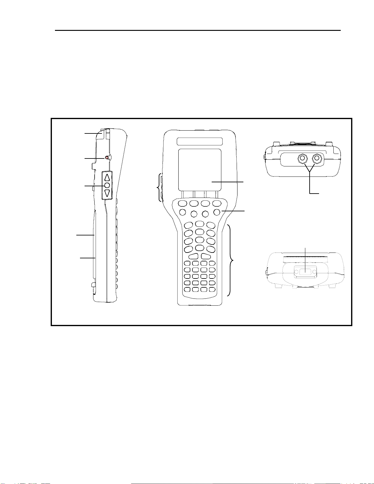
2.0 DISPLAY OVERVIEW ................................................................................................2-1
2.1 HEADER LINE SYMBOLS ...............................................................................................2-1
2.2 KEYPAD OVERVIEW......................................................................................................2-1
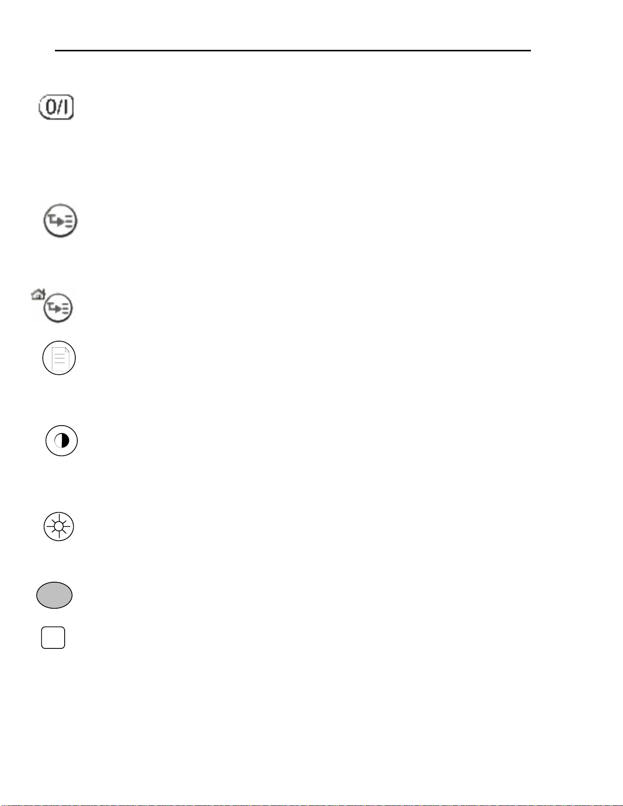
2.3 KEYPAD SYMBOLS........................................................................................................2-2
3.0 GENERAL OPERATION.............................................................................................3-1
3.1 POWER OPTIONS............................................................................................................3-1
3.2 NAVIGATING MENUS ....................................................................................................3-1
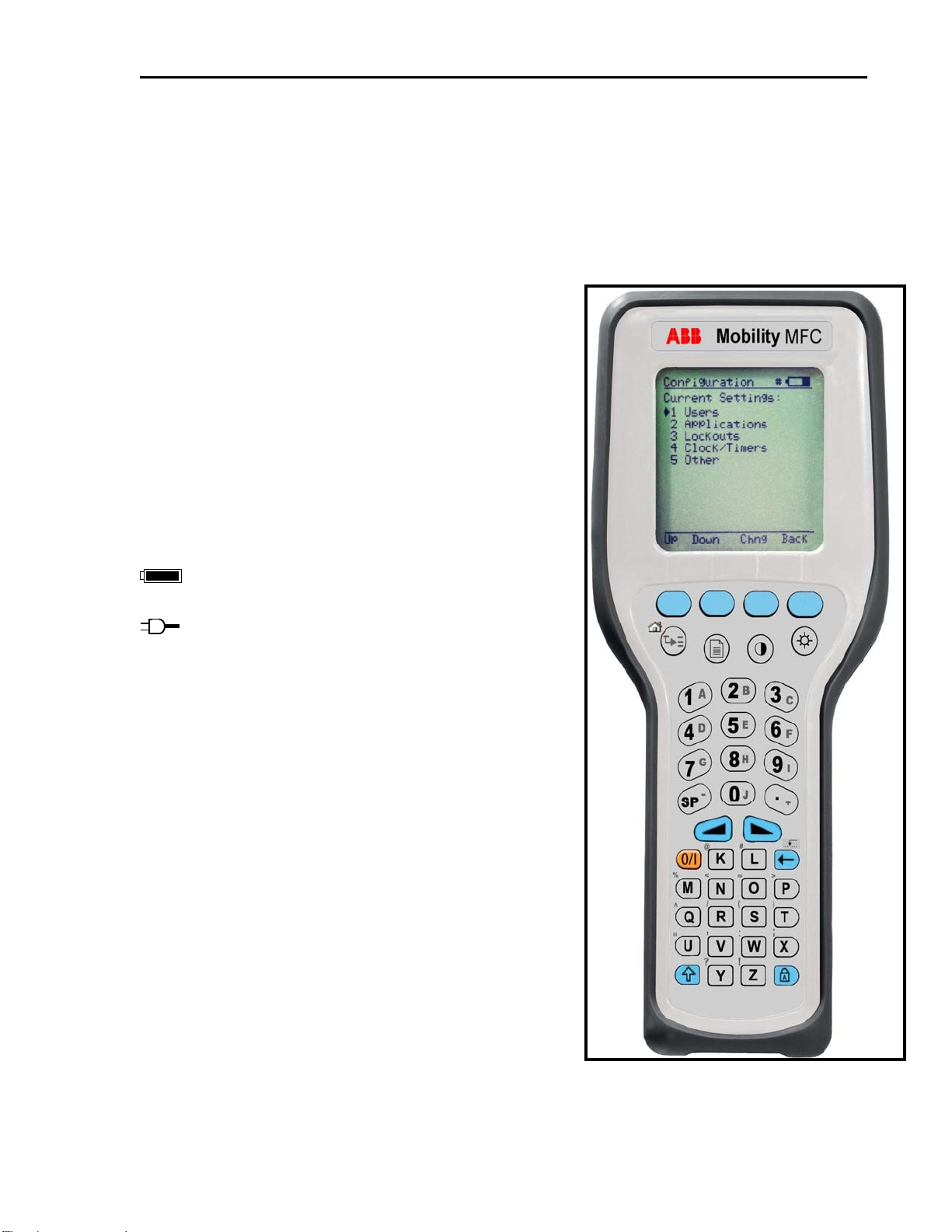
3.3 TURNING ON THE MOBILITY MFC ................................................................................3-2
3.4 MOBILITY MFC MAIN DISPLAY ...................................................................................3-2
3.5 MOBILITY MFC CONFIGURATIONS SETTINGS...............................................................3-3
3.5.1 Lockout Feature.........................................................................................................3-3
3.5.2 Backlight (off timer)...................................................................................................3-4
3.5.3 Off Timer....................................................................................................................3-4
3.5.4 Clock Edit...................................................................................................................3-4
3.5.5 Enter PC Comm. Mode..............................................................................................3-4
4.0 BATTERY INSTALLATION & REMOVAL ............................................................4-1
5.0 EXTERNAL CONNECTIONS TO MOBILITY MFC..............................................5-1
6.0 HAZARDOUS AREA USE...........................................................................................6-1
6.1 INTRINSICALLY SAFE CERTIFICATION...........................................................................6-1
7.0 HART®COMMUNICATIONS WITH THE MOBILITY DHH800-MFC..............7-1
7.1 OVERVIEW....................................................................................................................7-1
7.2 HART®COMMANDS.....................................................................................................7-1
7.3 HART®CONNECTIONS.................................................................................................7-1
7.4 HART®COMMUNICATIONS..........................................................................................7-2
7.4.1 Initial Screens / Online Mode....................................................................................7-2
7.4.2 Multi-drop Poll ..........................................................................................................7-3
7.4.3 Manual Launch of Device 0 Poll...............................................................................7-3
7.4.4 Offline Menu Mode....................................................................................................7-3
7.4.5 Online Setup (or Config) Mode .................................................................................7-5
7.4.6 Communications Trouble Shooting............................................................................7-5
7.4.7 More Status Message.................................................................................................7-6
7.4.8 Save / Send Configuration Functions ........................................................................7-6
8.0 DOCUMENTING HART CONFIGURATIONS WITH MOBILITY DMS ...........8-1
9.0 MOBILITY MFC DEVICE SPECIFIC & GENERIC HART®
CONNECTION..........................................................................................................................9-1
9.1 USING GENERIC HART COMMUNICATION ...................................................................9-1
i

MOBILITY DHH800-MFC CONFIGURATOR INSTRUCTION MANUAL
10.0 DOF / FIRMWARE DOWNLOAD SITE .................................................................10-1
10.1 OVERVIEW..................................................................................................................10-1
10.2 WHO HAS ACCESS TO THE DOWNLOAD SITE?..............................................................10-1
10.3 PC REQUIREMENTS FOR DOWNLOAD OPERATIONS.....................................................10-1
10.4 PREPARING THE MOBILITY MFC ................................................................................10-1
10.5 KEEPING YOUR MFC UP TO DATE .............................................................................10-1
10.5.1 Prerequisites:.........................................................................................................10-1
10.5.2 Register MFC.........................................................................................................10-1
10.5.3 Check For Updates................................................................................................10-2
10.5.4 Update Handhelds .................................................................................................10-2
10.5.5 MFC Listing...........................................................................................................10-2
11.0 UPGRADING DHH800-MFC22 TO SUPPORT ALL HART DEVICES .............11-1
11.1 7 DAY TRIAL...............................................................................................................11-1
11.2 PERMANENT UPGRADE ...............................................................................................11-1
12.0 AVAILABLE DOF WEBSITE...................................................................................12-1
13.0 DPC MANAGER UTILITY .......................................................................................13-1
13.1 DPC MANAGER OPTION .............................................................................................13-1
14.0 RETURNING THE MOBILITY MFC FOR REPAIR............................................14-1
15.0 APPENDIX...................................................................................................................15-1
15.1 SPECIFICATIONS..........................................................................................................15-1
15.2 ORDERING INFORMATION ...........................................................................................15-2
15.3 ACCESSORIES..............................................................................................................15-3
16.0 INTRINSIC SAFETY CONTROL DOCUMENT....................................................16-1
17.0 HART®COMMAND STRUCTURE MENU TREE................................................17-1
17.1 2600T-262/264 REV.1MENU TREE ...........................................................................17-1
17.2 THX02 REV.1MENU TREE ........................................................................................17-2
17.3 TZID-C REV 2MENU TREE........................................................................................17-3
17.4 1151 REV.5MENU TREE............................................................................................17-4
17.5 3051 REV.2 MENU TREE.............................................................................................17-5
ii

MOBILITY DHH800-MFC CONFIGURATOR INSTRUCTION MANUAL
1.0 Mobility DHH800-MFC Configurator Overview
The Mobility DHH800-MFC Configurator is the latest handheld in the ABB family of HART Configuration
devices. All HART field devices can be configured, polled, and trimmed using the Mobility MFC with
HART communications. The Mobility MFC is a full function Configurator supporting HART Universal,
Common Practice and Device Specific commands for commissioning, configuration and maintenance
operations.
Figure 1-1 Mobility MFC with HART Communications
Top View
HART
connection
Battery
door
Side View
Lanyard
p
ins
(
2x
)
AC Adaptor
jack
Up, Select
Down thumb
keys
Hand
strap
Bottom View
DB-9 Serial
connection
Front View
Thumb
keys Display
Soft keys
Feature keys
Alpha numeric
and edit keys
Note: For Intrinsically Safe Mobility MFC models, consult the Hazardous Area Use section of this manual for
specific details on use of approved Mobility MFCs and applicable restrictions
1-1

MOBILITY DHH800-MFC CONFIGURATOR INSTRUCTION MANUAL
2.0 Display Overview
The display of the Mobility DHH800-MFC is a 128 x 128 pixel graphic display with backlight. Viewable area
is 2.6” x 2.6” for 13 viewable message lines. The display provides three types of information: 1) header
information including display titles, HART communication status indicator, SHIFT indicator, alpha or numeric
entry mode indicator and battery gauge, 2) main data display section for display of Mobility MFC operating
menus, HART menus, and device information, and 3) footer information defining the display’s soft key
functionality.
The following photo depicts the Mobility MFC Offline menu
and Soft keys:
2.1 Header Line Symbols
♥heart symbol indicates active HART
uup arrow indicates SHIFT key is on
# number sign indicates numeric / symbol entry is the present
entry mode for all dual functions keys
A letter indicates alpha entry is the present entry mode for all
dual function keys
battery symbol indicates Mobility MFC under battery
power; filled portion indicates remaining battery
electrical plug symbol indicates the AC adapter is
connecting and powering the MFC
BUSY text box replaces either power symbol when
the microprocessor is busy executing a previou
requested task. Do not press keys when this status
symbol is displayed.
sly
nction.
ift
two separate functions as needed to
cilitate data entry.
ttom of the
CD, just above their respective gray soft keys.
used to scroll up, scroll
own, and to select menu items
2.2 Keypad Overview
The Mobility MFC keypad has three basic key types: single
function keys, dual-function keys, and soft keys with changing
definitions.
Single function keys control a dedicated Mobility MFC
fu
Dual-function keys, through the use of the Alpha Lock or Sh
keys, toggle between
fa
Soft key functions change depending on the present operating
mode. Soft key definitions are displayed at the bo
L
The left hand thumb keys can be Figure 2.1 Mobility Hand-Held
d
2-1

MOBILITY DHH800-MFC CONFIGURATOR INSTRUCTION MANUAL
2.3 Keypad Symbols
On/Off
Pressing the 0 (Off) / 1 (On) key powers up or turns off the Mobility MFC. As the unit powers up, an
internal diagnostic check is performed. Any abnormalities are posted on the display. The unit will
briefly display the Mobility MFC model number and then check for a HART device with address of
zero. If a device with zero address is found, the Mobility MFC immediately goes into online status and
displays information about the device. If no device is found, the Mobility MFC enters the Mobility MFC
Main navigation screen. To turn the Mobility MFC off, press and hold the ON/OFF key for
approximately .5 seconds. Unit will power down provided a critical HART operation is not in process.
Quick Menu
The Quick Menu key initiates HART communications and then displays ten (10) HART menu choices
for the connected device. These menus are used to short cut the traditional HART menus to enable
the user to arrive quickly at the desired functions. Typical Quick Menu options include: Main Menu,
Config Menu, Rerange, Basic Info, Construction Materials, Display, Sensors, Signal Conditioning,
Self Test. Quick Menu is disabled while critical HART operations are in process.
Home
The key sequence SHIFT, Home returns the user to the initial or “home” HART menu for the
connected device. The Home function is disabled while critical HART operations are in process.
Document
This key provides rapid access to HART communication Save/Send Configs options, List/Edit
Configs, and Create Configs functions for all Mobility MFC models. This key also provides
documenting functions used with the ABB Device Management System software. Access to this
key is disabled while critical HART communications are in process.
Display Contrast
This key allows the user to adjust the contrast of the LCD display for ambient lighting and user
preferences at any time and in any operating mode. Pressing and holding this key cycles through all
available contrast settings. If the display is faded or blacked out, simply depress the key until the
display returns to an acceptable level. After adjusting Display Contrast, wait at least five (5) seconds
before turning unit off to insure storage of new contrast setting. Ambient temperature compensation
is included in the Mobility DHH800-MFC.
Back Light
This key provides a backlight to illuminate the display in poor light conditions. Battery life is impacted
by long-term use of the backlight feature. An automatic shut off timer is available to the user under the
Main Menu’s Mobility MFC soft key.
Alphanumeric / Symbol Entry
The alphanumeric keys have the heaviest population on the keyboard and are the method of entering
data into the Mobility MFC. Each Mobility MFC display has a default alpha or numeric / symbol entry
mode based on the most likely used mode for the display’s function. This reduces user workload to a
minimum. Pressing the ALPHA LOCK key activates the other entry mode at the user’s convenience.
Pressing the SHIFT key converts the next keystroke to the inactive entry mode and then automatically
reverts back to the default mode. The letter “A” in the display header line indicates the alpha input
default is active while a # sign in the display header indicates the numeric / symbol input is the default.
2
B
L
2-2

MOBILITY DHH800-MFC CONFIGURATOR INSTRUCTION MANUAL
Shift
The SHIFT key is used to activate the secondary functions of the Mobility MFC’s dual-function keys
for the next keystroke only. When the SHIFT key is active, an up arrow uis displayed at the top of
the display to the left of the battery power (or AC wall plug) symbol. SHIFT is also used to activate
the Page Up and Page Down soft key functions while viewing lists of information (installed DOFs,
stored configs, etc…).
Alpha Lock
This key changes the keypads dual function keys from numeric/symbol entry mode to alpha
character entry mode and back. The present entry mode is indicated in the display header line next
to the power supply indicator on the upper right of the screen. The letter “A” in the display header
line indicates that alpha entry is active while a # sign in the display header indicates that numeric /
symbol entry is active.
Left / Right Arrow keys
These keys support cursor movement forward and backward for text / numeric editing needs. The
default edit mode is “overwrite.” For navigating functions, the left arrow emulates the Back soft
key and the right arrow emulates the Select soft key.
Delete
This editing key will delete the character located above the cursor in a text / numeric string.
Insert
Pressing the Shift, INS key sequence activates the Insert text edit function. Once activated, the
next alpha or numeric / symbol keystroke will be inserted into the open text field. The “overwrite”
default mode is restored upon completion of the insert operation.
Soft Keys
The four light blue keys located immediately below the display are Soft Keys. The specific functions
of these keys change depending on the operating mode of the Mobility MFC. Present definitions are
displayed at the bottom of the Mobility MFC display. The following are examples or Soft Key
definitions and their uses:
Up – moves indicator arrow up one line in a menu list
Down – moves indicator arrow down one line in a menu list
Select – selects the indicated menu item
MFC – provides access to Mobility MFC configuration settings (Lockout, Backlight timer, Off timer
Clock Edit, PC Comm Mode, and Model Info)
Back – returns to prior display
Inc – Increment the value shown above the cursor
Dec – Decrement the value shown above the cursor
Next / Prev – these keys move to Next or Previous item within the list function accessed. Next
and Prev are for navigation only.
Done – Ends data entry session and proceeds with the selected operation
Edit – activate edit function for displayed parameter
Abort – aborts present operation without affecting prior settings or values
Save – saves the present value
Store – stores the present value
Yes – affirmative response to question presented
No – negative response to question presented
Trim – executes the trim function called for by the HART menu option selected
2-3

MOBILITY DHH800-MFC CONFIGURATOR INSTRUCTION MANUAL
Thumb operated keys
Up, Select, and Down side keys provide convenient alternate methods of menu navigation. Use these in
tion to Soft keys and numbered HART menu lines to make menu navigation fast and easy.
addi
= Up = Prev
= Select, Edit Do not use these keys when the symbol is displayed.
= Down = Next
BUSY
2-4

MOBILITY DHH800-MFC CONFIGURATOR INSTRUCTION MANUAL
3.0 General Operation
3.1 Power options
The Mobility DHH800-MFC can be powered for portable operation by two each 9-volt alkaline, Lithium or
NiMH batteries. Alkaline batteries are standard with the Mobility MFC shipment. ABB offers NiMH batteries
and charger cradles (external charge only) as an option. For bench top operations and download operations,
an AC adapter (P/N 3KXD311800L0036) with a barrel style connector is recommended. Previous DHH800-
MFC hardware used a pin style AC adapter connector (P/N 3KXD311800L0034).
Located in the upper right corner of the display, this icon displays the
remaining battery power. Fresh batteries produce a full black cell body. As the power
drains, the black segment retreats indicating remaining power.
When the Mobility MFC is used with the optional AC adapter (P/N 3KXD311800L0036), the battery
circuit is bypassed and a wall plug icon replaces the battery icon on the display header. The AC
adapter jack is located on the left side of the Mobility MFC.
NOTE: Power icons may temporarily disappear during certain HART Communication operations
3.2 Navigating Menus
Several methods of navigating through the Mobility MFC menus are available to the user for maximum
convenience and utility.
1. Soft keys: Use Up and Down Soft Keys to move cursor arrow to the desired menu option. Then
use the Select soft key to accept the indicated choice. Soft key navigating tools are found
throughout the Mobility MFC Main displays and HART communication displays.
2. Side keys: Up, Down and Select keys are also provided on the left hand side of the Mobility MFC.
These keys are thumb operated and provide a convenient alternative to the Soft Key navigation
buttons. Side key functionality is not always available in the HART communication displays.
3. Multi-page lists: Multi-page lists have a and/or symbol along the right hand side of the display
indicating the existence of information on the previous or next page(s). Several pages of information
may need to be viewed when reviewing lists of installed DOFs, stored configuration files or finding a
specific device in Offline Mode to create a configuration for. While in these list areas, pressing the
SHIFT key changes soft key definitions Select and Back to PgUp and PgDn, respectively. To
quickly advance to the next page of a list, press SHIFT and then the PgDn soft key. To retreat to the
prior page, press SHIFT and then PgUp. After SHIFT is pressed the PgUp and PgDn soft keys
remain active until the Up or Down soft key is used or until SHIFT is pressed again.
4. Numbered HART menus: All HART displays have numbered menu lines when needed. This gives
fast access directly to the desired menu line. Mobility MFC displays also have numbered menus
with the exception of multi-page list screens and the Mobility MFC Configuration screen.
5. HART menu HOME key: To quickly retreat from any location in the HART menu to the initial HART
menu screen for a device, press the SHIFT, HOME key sequence. This will return the display to the
initial HART screen. The Home function will be disallowed if a critical HART task is in process.
6. Left / Right Arrow keys: Emulate Back and Select soft keys, respectively
3-1

MOBILITY DHH800-MFC CONFIGURATOR INSTRUCTION MANUAL
3.3 Turning on the Mobility MFC
Use the dedicated ON/OFF key to power up the Mobility MFC. A brief diagnostic runs while the “Powered by
Meriam and ABB” logo, Mobility MFC model number, and Mobility MFC firmware version are displayed. A
message is displayed indicating the Mobility MFC is scanning for a HART device at address zero. The
following scenarios are possible.
Online #
2600T-262/264 : PT-1012D
1 Configure
2 Pres: 3.523 inH2O@20C
Sensor temp: 74.04 degF
Static Pres: 14.50 psi
Free Variable: 100.01 ft
Analog Output: 4.8 mA
PV% Range: 5.50%
Up Down Select Back
3
4
5
6
7
1. If the Mobility MFC is connected to a HART device with address
zero (and there is sufficient loop resistance), the Mobility MFC
immediately establishes HART communication with the device.
A display similar to the example at right appears. The numbered
menus and Soft Keys are then used to commission, re-configure,
or maintain the connected device.
Figure 3-1 If connected to
HART Device
2. If no HART device is connected, a HART device with
address ≠0 is connected, or a connected device is not found
due to wiring or loop resistance problem, the Mobility MFC will
enter the Mobility MFC Main navigation display depicted at right.
Mobili
#
ty MFC Main
Devi
1 Onlin
2
Up D
ce 0 Not Found
e Setup
Offline Menu
own Select MFC
2.1 Select Online Setup once a HART device is connected
or once the wiring problem is resolved. A proper
connection will be indicated when line two changes to
“Device 0 *Online*”.
2.2 Select Online Setup if properly connected HART device
is setup for Multi-drop loop or Burst Mode operation
(device address ≠0). The Mobility MFC will immediately
initiate a multi-drop poll to find all non-zero addresses on
the loop.
Figure 3-2 If not connected
to HART Device
Mobili
#
ty MFC Main
ce 0 *On-line*
e Setup
Offline Menu
own Select MFC
Devi
1 Onlin
2
Up D
3.4 Mobility MFC Main Display
The Mobility MFC Main display (Figure 3-3) provides access to Online
Setup, Offline Menus and to Mobility MFC configuration settings via the
right hand Soft Key.
1. Online Setup is described above in Turning On the Mobility
MFC. Figure 3-3 Main Display
Configuration #
Current Settings
Disabled
ight: 2 min
imer: Disabled
ck Edit
Enter PC Comm. Mode
own Select Back
Lockout :
Backl
Off T
Clo
Model Info
Up D
2. Offline Menu is selected to provide access to Offline Utilities
such as List / Show DOFs, List / Edit Configurations, and Create
Configurations. The number of DOFs installed (HART
device profiles) and the number of device Configurations stored
are also available on Offline Utilities screen.
3. MFC Soft Key is selected to configure Mobility MFC settings and
view Mobility MFC information such as Model, Serial, and
Firmware numbers, DOFs installed and Configurations stored. Figure 3-4 Offline Menu
3-2

MOBILITY DHH800-MFC CONFIGURATOR INSTRUCTION MANUAL
3.5 Mobility MFC Configurations Settings
3.5.1 Lockout Feature
The Mobility MFC HART Communicator can be programmed to lock out certain standard functions that a
supervisor may wish to control. The functions included are used to set up the Mobility MFC for normal use,
change online HART device configurations, create offline HART device configurations, update the installed
DOFs list (HART device profiles), or to update the Mobility MFC’s operating firmware. For example, locking
out the Configs feature turns the Mobility MFC into a read only HART communicator while locking out DOFs
and Firmware prevents unauthorized updates. The lock out can be limited to individual Lockout Details items
or all Lockout Details items can be locked out at one time.
To enable the lockout feature, move the selection cursor to the Lockout menu option on the
Configuration screen (see above). Choose the Lockout selection by pressing the Select soft key. The
Mobility MFC will enter the Lockout Enable / Disable Screen. The current status is shown and three
choices are provided:
Configuration #
Lockout: Disabled
Disabled
Enabled
View Details
Up Down Select Back
Configuration #
Lockout Details
All : Disabled
Setting : Disabled
DOFs : Disabled
Configs : Disabled
Firmware : Disabled
U
p
Down Select Back
Figure 3-5 Lockout Enable/
Disable Screen Figure 3-6 Lockout View
Details Screen
Disabled: All lockout features are disabled and all options on the menu are accessible for reconfiguration.
Enabled: Enables the lockout selections that are set in the Lockout Details screen (above left).
View Details: This option takes the user to the Lockout Details screen listing all Mobility MFC parameters that can be
protected by lockout (see above left). Individual functions can be locked or, if preferred, the lockout can be set to deny
unauthorized access to all parameters.
To enable the lockout option, select Enabled on Lockout Enable / Disable Screen by scrolling Down and
pressing Select. The screen will switch back to the original Settings screen that now shows the lockout
status as Enabled.
Scroll Down to View Details, and press Select. This screen allows the user to choose which parameters to
lockout. Use the Up and Down keys to scroll through the selections and press Select to choose the desired
setting(s). The screen will change and prompt you to Enable or Disable lockout for that function. Scroll
Down to Enable and press Select.
Lockout Code
At this point the user will be prompted to enter a 3-digit lockout code. This code will be required to gain
access and change any parameter previously locked out. Use the Increment, Decrement and Next Soft
Keys to input a lockout code value. Alternatively you may use the light blue keys for
Increment and Decrement functions. When you are satisfied with the lockout code value, press Store.
IMPORTANT: After the code is entered, the user must cycle the power to activate the lockout
mechanism! BE SURE TO SAVE THIS CODE IN A SAFE PLACE IN THE EVENT YOU FORGET
THE NUMBER. ACCESS TO LOCKED-OUT FEATURES WILL BE DENIED WITHOUT THE
PROPER CODE.
3-3

MOBILITY DHH800-MFC CONFIGURATOR INSTRUCTION MANUAL
To Disable Lockout
function or edit a value that is protected by the lockout code, enter the three
Changing the Lockout Code
le the lockout function for all the parameters selected, shut the
.5.2 Backlight (off timer)
bility DHH800-MFC series allows the user to set the backlight to shut off after
he shutoff timer can be disabled or set to shut off after time periods of from 1 minute up to 30 minutes.
OTE: The Backlight Off Timer is disabled when the optional AC Adapter (P/N 3KXD311800L0032) is
.5.3 Off Timer
life, the Mobility DHH800-MFC series allows the user to set the unit to shut off after a
OTE: The Off Timer is disabled when the optional AC Adapter (P/N 3KXD311800L0036) is powering
.5.4 Clock Edit
n allows the user to correct the date and time of the Mobility MFC’s internal clock. To
w
hoose a clock or date option to adjust by scrolling Up or Down. Press Select to choose that option. Enter
u
-year life e
.5.5 Enter PC Comm. Mode
d to a PC for updates via DPC Manager (see DPC Manager section in
rox. 2
When you wish to use a
digit Lockout code when prompted and press Save. You will now be able to use the function or edit
the setting as normal. Entering an incorrect code will display the message “Incorrect Code” and allow
you to try again.
To change the lockout code, disab
unit off, and follow the procedures outlined above.
3
To conserve battery life, the Mo
a certain period of keypad inactivity. To change the backlight off timer on the unit, scroll Down to Backlight
and press Select. Scroll Up or Down to the auto shut-off time desired. Press Save to select the new value.
T
N
powering the Mobility MFC.
3
To conserve battery
certain period of keypad inactivity. To change the off timer on the unit, scroll Down to Off Timer and press
Select. Scroll Up or Down to the auto shut-off time desired. Press Save to select the new value. The
shutoff timer can be disabled or set to shut off after time periods of from 1 minute up to 2 hours.
N
the Mobility MFC.
3
The Clock Edit optio
select the Clock Edit feature, make sure the pointer arrow is pointed to this selection. If not, scroll the arro
Down using the soft keys. Choose Clock Edit by pressing the Select soft key.
C
the correct value using the numeric keypad and text edit key if needed. When complete, press Done. You
will be asked if you wish to save the new data. Press Yes to accept the new value. Pressing No will take yo
back to the Clock Edit without making any changes to the Mobility MFC clock.
NOTE: When replacing the batteries, the date and time will remain active. An internal, 10
back-up battery continuously powers date & time information. This battery is not serviceable by th
user.
3
When the Mobility MFC is connecte
this manual), a DB-9 serial cable is used. Occasionally a DB-9 Serial cable is encountered that does not
have a DTR line. The DTR line is important to the update process because it is used to initiate and confirm
communication between the two machines. If a DB-9 cable without a DTR line is used, the Mobility MFC
must be manually placed in the Enter PC Comm. Mode. Go to the Mobility MFC Main display and select
Mobility MFC. Scroll down to the Enter PC Comm. Mode menu option and press Select. Proceed with
update and cycle Mobility MFC power when the update is complete. It is recommended to use fresh
batteries or an AC adaptor during update procedures. This mode will automatically time-out after app
minutes of inactivity and return to the main display.
3-4

MOBILITY DHH800-MFC CONFIGURATOR INSTRUCTION MANUAL
4.0 Battery Installation & Removal
The Mobility MFC monitors battery condition and displays a “REPLACE BATTERY” notice when the batteries
get low. The Mobility MFC will function for a short period of time after the notice is posted.
To install or remove the batteries, remove any soft case or protective boot and turn the Mobility MFC face
down on a work surface. Use a flat screwdriver to loosen the captive screw holding the battery door closed
and remove door. Replace batteries and make sure all connections are firmly secured. Replace door,
tighten screw and replace the soft case or boot.
Note: Replace both 9-volt batteries at once with all alkaline, all lithium or all NiMH cells. Do not mix
alkaline, lithium or NiMH batteries with each other or with other battery types. Battery replacement is
recommended when the “Replace Batteries” notice is posted on the display; however, the Mobility
MFC will function for a time after the notice is posted.
Note: For Intrinsically Safe Mobility MFC models, replace batteries only in Non-Hazardous Areas.
Replace batteries with approved types only. See the Mobility MFC Intrinsic Safety Control Document
in the Appendix of this manual for approved battery details.
4-1

MOBILITY DHH800-MFC CONFIGURATOR INSTRUCTION MANUAL
5.0 External Connections to Mobility MFC
1. AC Adapter – The Mobility DHH800-MFC can be powered by external AC Adapter connected to the jack
located on the left side of the Mobility MFC. P/N 3KXD311800L0036 bypasses the battery circuit to power
the unit. The battery symbol in the display header is replaced by a wall plug symbol.
WARNING: Serious injury or death may result from explosions. Do not make connection to the AC
adapter jack in a hazardous area. Use the AC adapter only in non-hazardous areas.
2. HART lead set – All Mobility MFC models are equipped with a standard size banana jack on 0.75” center.
The lead set supplied with the Mobility MFC has a standard banana plug on one end and mini-grabbers on
the other for convenient connections.
Note: For Intrinsically Safe Mobility MFC models, verify the instruments in the loop are installed in
accordance with intrinsically safe field wiring practices before making connection from the field
device to the Mobility MFC’s HART jack. See Hazardous Area Use Section of this manual for
Intrinsically Safe guidelines / restrictions.
3. DB-9 Connection Port – All Mobility MFC models are equipped with a standard DB-9 connection for RS-
232 communications located on the Mobility MFC’s bottom end. The DB-9 provides the hardware interface to
facilitate download / upload operations from a host PC. This connection port facilitates download of Mobility
MFC firmware improvements, HART®Device Object Files (DOFs) and documenting operations. All Mobility
MFC upgrades are available via the DPC Manager Download Site (refer to the DOF/Firmware Download Site
section in this manual). The Mobility MFC does not need to be returned to ABB for firmware updates or for
the addition of DOF files.
Note: Do not use the DB-9 connection port in Hazardous Areas. Use in non-hazardous areas only. See
Intrinsic Safety Control Document in the Appendix for more details on I. S. Mobility MFC units.
5-1

MOBILITY DHH800-MFC CONFIGURATOR INSTRUCTION MANUAL
6.0 Hazardous Area Use
6.1 Intrinsically Safe Certification
The Mobility DHH800-MFC Configurator with HART Communications are available with Intrinsically Safe
Certification for use in Class I, Division I, Groups A, B, C, and D, T5 hazardous areas. Refer to the
Intrinsically Safe Control Document in the Appendix of this instruction manual for more details. The
certification is to CAN /CSA-22.2 No.1010.1 & 157-92 and UL913 Fifth Edition Rev 2/21/97.
The following table identifies Mobility MFC model numbers and Areas of acceptable use.
Model Number Non-hazardous
Area
Hazardous
Area
Mobility DHH800-MFC-xxx-00 √NO
Mobility DHH800-MFC-xxx-01 √√
Mobility MFCs with Intrinsically Safe certification can be identified by model number (see table above or the
Intrinsically Safe Control Document in the Appendix) or by a special label on the unit. A sample of the label
is shown below.
WARNING: Serious injury or death may result from explosions. Do not make connection to the DB –
9 connection port or to the AC adapter jack while in a hazardous area.
WARNING: Serious injury or death may result from explosions. Before making electrical
connections to an Intrinsically Safe Mobility MFC at the HART jacks, verify the instruments in the
loop are installed in accordance with intrinsically safe field wiring practices.
Note: Restrictions apply to the use of Intrinsically Safe Mobility MFC units in hazardous areas. Refer
to the Intrinsically Safe Control Document in the Appendix for exact details. ABB reserves the right
to revise the Control Document without notice. Contact ABB (see page I, Assistance for contact
information) for the current Intrinsically Safe Control Document.
For Intrinsically Safe Mobility MFC models, consult the Hazardous Area Use section of this manual
for restrictions, for special instructions in use, and for electrical connections.
6-1

MOBILITY DHH800-MFC CONFIGURATOR INSTRUCTION MANUAL
7.0 HART®Communications with the Mobility DHH800-MFC
7.1 Overview
The Mobility DHH800-MFC Configurator with HART communications provides device specific HART
communication functions that allow the user to poll, configure and maintain supported HART field device.
The Mobility DHH800-MFC uses Universal, Common Practice and Device Specific commands to facilitate
communication with a HART field device. Use the Mobility MFC to commission devices, operational re-
configuration needs, or maintain devices through analog and sensor trim adjustments and many other
features.
The Mobility DHH800-MFC communicates with any HART device through Universal and Common Practice
Commands using the standard Generic DOF (Device Object File) but must have the DOF for a specific
HART device installed before it can execute Device Specific Commands. Consult the large and growing list
of available DOFs for an up to date list of HART devices with device specific support. Refer to the Available
DOF Website section of this document for information on accessing this list. When HART device support for
new devices becomes available, the Mobility MFC can be easily field updated via Internet downloads.
7.2 HART®Commands
Three HART command types are used by the Mobility DHH800-MFC to communicate with HART field
devices. First, Universal Commands are primarily used to identify a field device by its model number and tag
number and to read process data from the device. This communication is referred to as “polling”. The
Mobility DHH800-MFC can poll any Hart Device. Second, Common Practice Commands are used for
calibration and maintenance functions that are common to many devices. An example of this would be trims
or adjustments for the devices’ analog outputs. Third, Device Specific Commands are used to handle
functions that are unique to a particular device or manufacturer. Examples of these commands include
sensor zero, sensor trim, calibration curve characterization, density inputs required for calculations made by
the HART device or other configuration functions unique to the specific device.
7.3 HART®Connections
HART connections are made using two standard banana jacks (3/4” center) located at the top end of the
Mobility DHH800-MFC. Refer to the following diagram. Polarity is not a concern for HART connections so
both jack collars are black. ABB supplies a HART lead kit (P/N 3KXD311800L0011) complete with mini-
grabber connections and a 250 Ωload resistor with each model Mobility DHH800-MFC.
Figure 7.1 Mobility DHH800-MFC with HART
®
HART®connections are standard banana jacks (3/4” center)
For low load loops (less than 250 Ω), a 250 Ωresistor will need to be added to the loop to insure reliable
HART communications. ABB supplies a 250 Ωload resistor in the form of a standard adaptor (P/N
3KXD311800L0012). Refer to Figure 7-2 for connection details.
7-1

MOBILITY DHH800-MFC CONFIGURATOR INSTRUCTION MANUAL
Figure 7-2 Low-Load Loops
When connecting the Mobility DHH800-MFC to a loop with a resistive load greater than 250 Ωs, the HART
jacks may be connected across the loop + and – or to the HART device communication terminals. Refer to
Figure 7-3 for connecting across the loop + and -.
Figure 7.3 Connecting to the Mobility MFC
communication terminals, R Loop > 250 OHMS
7.4 HART®Communications
7.4.1 Initial Screens / Online Mode
Upon power up the Mobility MFC automatically detects if a field device is connect and attempts to establish
HART communications. When a device with address zero is found, the Mobility MFC provides feedback to
the user and starts the initial HART display for the connected device. See an example of Online Mode in
Figure 7-4.
Online #
T-262/264 : PT-1012D
1 Configure
2 Pres: 3.523 inH2O@20C
Sensor temp: 74.04 degF
Static Pres: 14.50 psi
Free Variable: 100.01 ft
Analog Output: 4.8 mA
PV% range: 5.50%
Down Select Back
2600
8
9
10
11
12
Up
Figure 7-4 Online HART Screen
7-2

MOBILITY DHH800-MFC CONFIGURATOR INSTRUCTION MANUAL
When no device connection is detected or a device with non-zero (Multi-drop or Burst Mode) address is
found, the message Device 0 Not Found is displayed and the Mobility MFC enters the Mobility MFC Main
navigation screen. The Mobility MFC Main screen allows the user to launch a multi-drop poll to find all
devices with non-zero addresses on the loop, to manually start an Online poll, or to enter Offline Mode.
Mobility MFC Main
#
Multidrop Polling…
Scanning Address #
Stop Abort
Figure 7-6 Multi-drop Polling
Screen
Multi-drop & Burst Mode Support
Figure 7-5 Mobility MFC Main
Navigation Screen
No device or Non-zero address found
Mobility MFC Main
#
Device 0 Not Found
1 Online Setup
2 Offline Menu
Up Down Select MFC
Mobility MFC Main
#
Device 0 *On-line*
1 Online Setup
2Offline Menu
Up Down Select MFC
Figure 7-7 Mobility MFC Main
Navigation Screen
Manually launch polling on
Device 0
7.4.2 Multi-drop Poll
To initiate a Mult-drop Poll, select the Online Setup option from the Mobility MFC Main screen when the
Device 0 Not Found message is displayed. This function polls for all non-zero addresses (1 – 15).
Located addresses are listed on the display as the remaining addresses are checked. When polling is
complete, or upon pressing Stop after the address of interest is found, use the soft key controls to select the
address of interest. The initial HART menu for the device selected will then be displayed for use.
7.4.3 Manual Launch of Device 0 Poll
When the message Device 0 *On-line* is displayed on the Mobility MFC Main navigation screen,
selecting Online Setup will launch HART communication with the device. The message indicates that a
HART device with address 0 has been detected at the HART connection and the Mobility MFC is
standing by to initiate communications. The Device 0 *On-line* message is shown 1) if a physical
connection is made to a HART device after the Mobility MFC power is turned on or 2) if the user exits
from a HART communication session using the soft key controls provided.
7.4.4 Offline Menu Mode
The Offline Menu gives the user access to lists and functions that can be viewed or performed in Offline
Mode at the user’s convenience for the purposes of reviewing the Mobility MFC’s DOF list, reviewing stored
device configurations or creating HART configurations. Stored configurations can be also be edited and then
applied later to a connected HART device. When the Offline Menu is selected from the Mobility MFC Main
navigation screen, the following display is shown.
Offline #
Utilities
1 List/Show DOFs
2 List/Edit Configs
3 Create Configs
4 Delete All Configs
DOFs Installed: 154
Configs Stored: 3
Up Down Select Back
Figure 7-8 Hart Offline Menu
Screen
7-3
Table of contents