ENGLISH
ABI-MM1001S40
Smart Music
Class-D DIN-rail amplifier
Stereo 2x20WRMS
Installation and userguide
1Contents
•1xDIN-rail amplifierABI-MM1001S40
•1xOmniMediaHD patchcord,45cm
•1xPower SupplyJumper cordfor SmartMusicmodules
•1xStereo 3.5mm to3.5mm jumpercord
2Introduction
The ABI-MM1001S40 isaverycompact stereo power amplifier.The
moduleisDINrail mountableand is3DINpositionswide.The
amplifieris capableofdelivering 2x20WRMSinto4Ohmspeakers.
3Specifications
•Power: max2x20WRMS into4Ohm
•Max. Gainapprox. 29,5dB (power stage)
•Preamplifier Gain:x1(0dB)or x4(+12dB)
•Power Supply: 14VDC
•THD+N@5W,1kHz:0,04%
•Frequencyrange (-3dB): 20Hztot22kHz
•Channelseparation 90dB
•Crosstalk>68dB(20Hzto22kHz)
•Efficiency ca.90%
•Switching frequency(spread spectrum):300kHz+-6kHz
4Connectors
5
PowerSupply
The amplifierrequiresa14VDCpowersupply.Themaximumcurrent is
3.2A.
The abitana power supplyABI-PS1003S00 hasbeen chosen tomeet
theserequirements.
It ispossibletodaisy-chainthe power supplytoasecond or eventually
third amplifier (maximum3amplifiersinone chain),using the supplied
jumper cables.
Importantremark: The maximumrequired power shouldnotexceed
the power limits ofthe power supply.
Incasemore than3amplifiersareconnected toapower supplywith
sufficientpower capacity,the powersupplyshouldhavemultiple
outputs.
6Installation
REMARK: TheBlackterminalsofthespeakerconnectorsareNOT
connectedtogroundandshouldNOT beconnectedtoanyother
black speakerconnectorterminal.
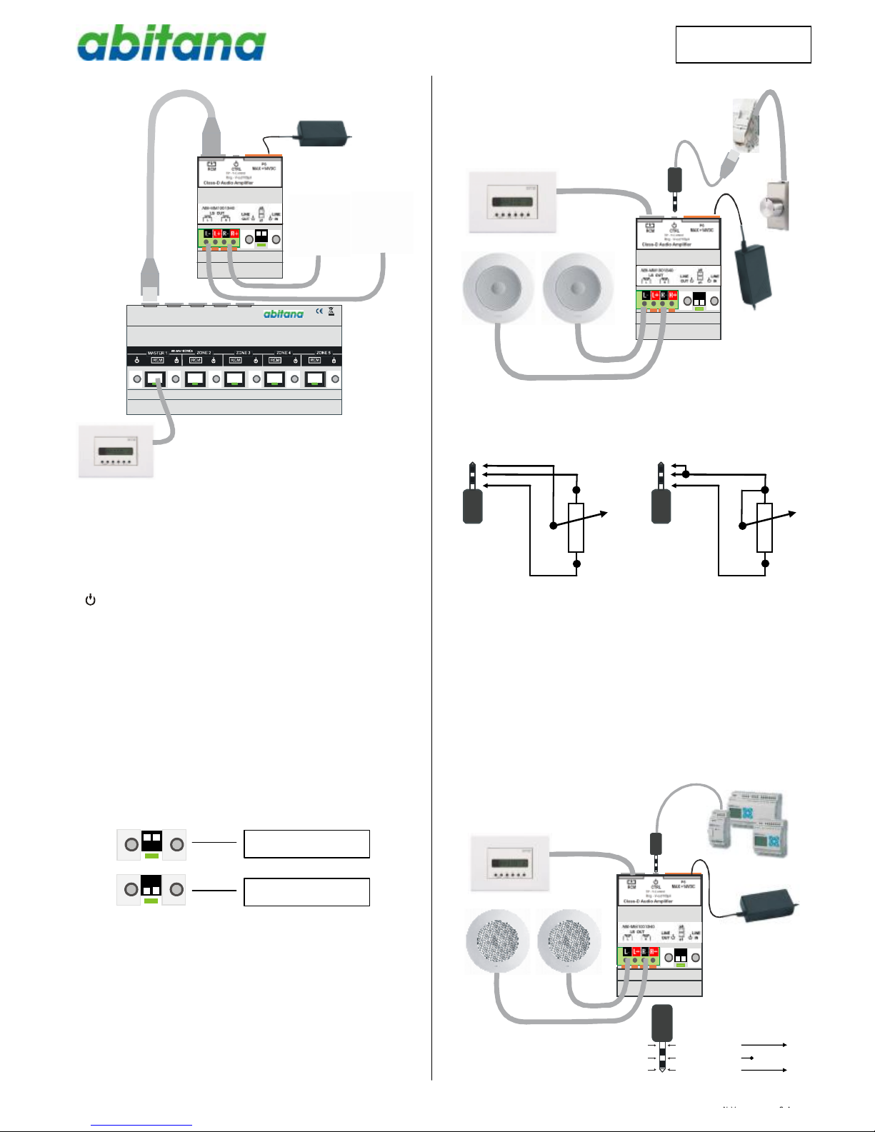
6.1Powersupplyand speakerconnection
Turn off thepower supply.Do notswitchonthepower supplyuntil all
connectionsare made.
Connect thespeakersthatbelongtothezone thatthisamplifierwill
servicetothe corresponding terminals.Stripthe wire over alengthof
5mm.Press theorange lever ofthe connector usingasmall
screwdriver and insertthe strippedwire inthe connector.Releasethe
screwdriver and makesure thatthewire is firmlyheldbythe contact.
Connect the power supplytothe corresponding terminalontopofthe
device.
6.2Connection oftheRadioandControlModule(RCM)
(ABI-MM1000Sxx)
Thisinstructionisonlyvalidforaninstallation in1roomwithoutmulti-
roommodule.
Connect the RJ45 jackon top ofthe unittothe RCMconnector by
means ofthe supplied patchcord.
When the power supplyisturned on,the RCMwill startand switchto
stand-by.Turn onthe RCMand checkthefunctionality.
L- L+ R- R+