Abitana ABI-EV2000S00 User manual

140507_ABI-EV20XX_QSG_ML_RevA.docx
NederlandsPagina 1 N.V. abitana S.A.
NEDERLANDS
ABI-EV2000S00
ABI-EV2008S00
ABI-EV2014S00
TV-over-Twisted-Pair
RF versterker
Installatiegids
1Inhoud vandeverpakking
•DIN-rail monteerbare modules voorbidirectionelebreedband
versterking
•Installatiegids
•3Afsluitweerstanden
2Gereedschap
•Moersleutel11mm
3Introductie
DeABI-EV2000S00 endeABI-EV2008 zijnbreedband versterkers
metgeïntegreerd retourpad.De toestellen zijnvoorzien van één
coaxingang voor KabelTV(CATV)aansluiting ofvoor de
aansluitingvaneen antenne en4onafhankelijkeRJ45(twisted-
pair) uitgangen vooraan.
Bij de ABI-EV2008S00 zijer ooktwee coaxTV
uitbreidingsuitgangen waaropde ABI-EV2014S00 kan
aangesloten worden omhetaantalbeschikbare uitgangen uitte
breiden tot 8of12.
Erzijneenaantaltwisted-pairnaarcoaxadapters(metofzonder
afregeling enfilters)beschikbaaromaandeontvangerzijde te
installeren (b.v.ABI-AC1001S00,ABI-AC1002S00,...).
De toestellen zijnconformde Docsisstandaard, in-band retourpad
geschiktop allepoorten ominteractievedigitaleTVdienstenvan
providers teondersteunen (b.v.VOO, UPC,...).
4Connectoren
5Voeding
De belastingsfactor voor ABI-EV2000S00 en ABI-EV2008S00bedraagt
0,6A.
De belastingsfactor voor ABI-EV2014S00 bedraagt 0,0A.
Maximaletoegelaten belastingsfactor (somvan belastingsfactors van
alleaangesloten modules)voor voeding ABI-PS1001S14 =4A.
6Installatie
Schakeldevoeding ABI-PS1001S14 uit door middelvan de
tweepolige schakelaar indecentralecommunicatiekast,ofdoor de
voedingsstekker van de voeding teverwijderen.
1.Zorg ervoor datde afschermingvan hetCATVovernamepunt
(of NIU)op een correctemanier geaard is.
2.Open de centralecommunicatiekast.
3.Plaats deABI-EV20XXS00 op de metalen DIN-rail (fig. 1).
4.DeABI-EV2000S00 enABI-EV2008S00 zijnvoorzien van een
aardingsdraad (1) dieverbonden ismetde ingangsconnector
(F-type).Deze draad dientverbonden teworden metde
veiligheidsaarding (4) van de installatie(zieonderstaande
tekening).
De volgende systeemonderdelendienen eveneensmetde
veiligheidsaarding verbonden teworden:HetDIN-rail frame
(2) en de voeding (3).
5.Bevestigéén van deongebruiktevoedingssnoeren van de
ABI-PS1001S14 voedingsblok(5VDC –4A)aan de
voedingsconnector van hetapparaat.
6.Verbind de CATV/ANTENNEingangsconnector bovenaan de
modulemethetCATVovernamepunt(NIU) ofmetde antenne
door middelvan een coaxkabel.
7.Verbind eventueelde uitbreidingsmodules(ABI-EV2014S00)
door middelvan een coaxpatchsnoer metde
CATV/ANTENNEuitgangen.
RFIN1
PSIN
+5VDC
CATV
RP
RFOUT2 RFOUT3
CATV
RP
CATV
RP
Enkel ABI-
E
V2008S00
PS1001
DIN-Rail Frame
PE1002
1
2
3
4
RFIN1
PSIN
+5VDC
SAT
CATV
RP
RFOUT2 RF OUT3
CATV
RP
CATV
RP
TV-over-Twisted-Pair
RFamplifier -4port-Master
ABI-AC1001S00
ABI-AC1002S00
ABI-AC1010S00
RF IN1
PS IN
+5VDC
CATV
RP
RF OUT2 RF OUT3
CATV
RP
CATV
RP
TV-over-Twisted-Pair
Slave-In-band RP TV-over-Twisted-Pair
Slave-In-band RP

140507_ABI-EV20XX_QSG_ML_RevA.docx
NederlandsPagina 2 N.V. abitana S.A.
NEDERLANDS
8.Span allecoaxconnectoren enafsluitweerstandenaan door
middelvan de moersleutel.
.
Het niet nalevenvandeinstructies (1) tot(7) indeaangeven
volgordekanbeschadiging vandeABI-EV2000/ABI-EV2008 tot
gevolghebben.
Wanneerhet niet mogelijkisomdeDIN-rails,frameofCATV
overnamepunt(NIU) teaarden, zorg erdantenminstevoordat ze
op hetzelfdepotentiaal staan(elektrischmetelkaarverbonden).
Zieookonzeaanbevelingaangaandeoverspanningsbeveiliging
aanhet eindevanditdocument
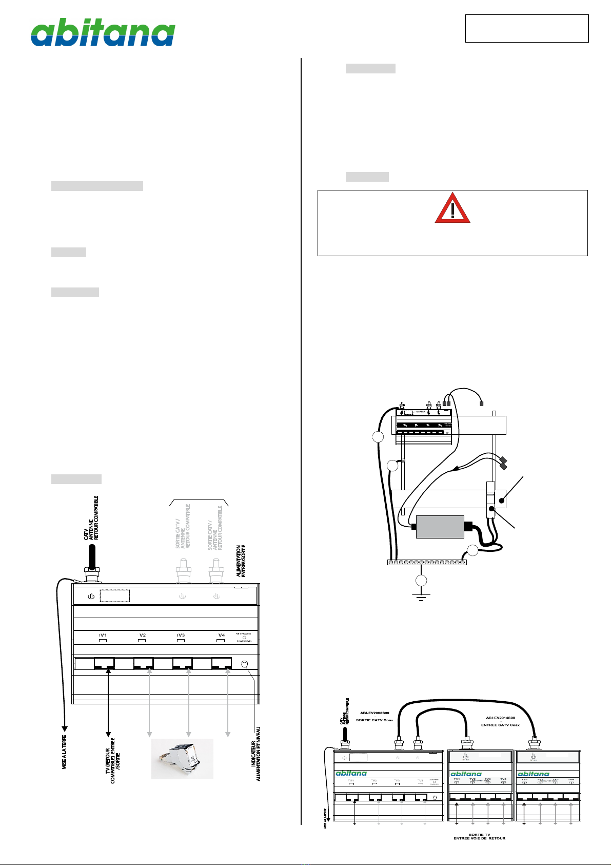
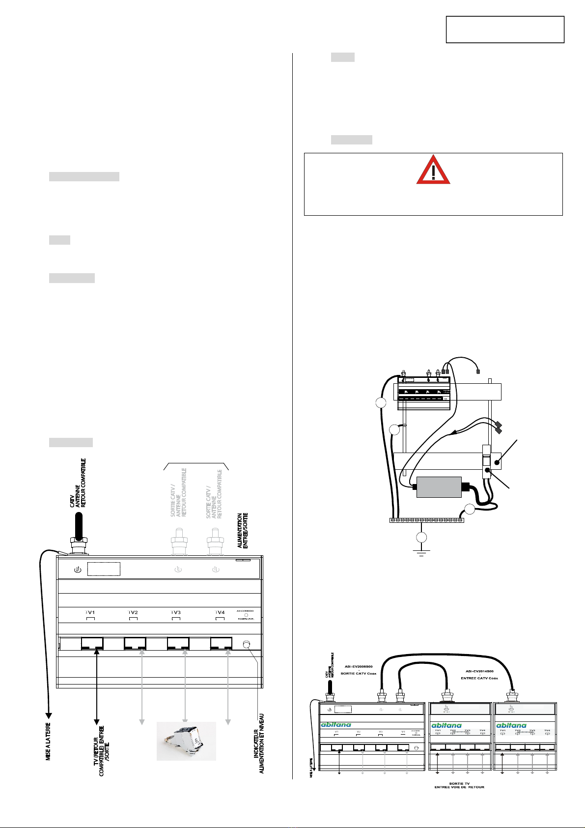
9.Zet de stroomaan.
10.De indicatorLEDopde voorzijde van de modulemoetnu
groen branden.Tijdenshetopstarten en nadien omde minuut
gaatde indicator knipperen.Bij een correct ingangssignaal
gaat de indicatorminstens 5maalknipperen.
Isde indicator rood,dan is ergéén ingangssignaal.
Is de indicator geel,dan ishetingangssignaaltelaag omde
gegarandeerde maximumkabellengtevan hetSmartMedia
netwerk(35m)tekunnen overbruggen.Indatgevaldienen
bijkomende metingen op hetingangssignaaluitgevoerd te
worden en desgevallend contactopgenomen teworden met
de operator.
11.Sluitde centralecommunicatiekast.
12.Kiesdemuurstekkerdiehetdichtststaatbij detelevisie,HDR
of decoder dieuwenstaan tesluiten.
13.Indien dezestekker zichdichter dan 15mbijde centralekast
bevindt, ishetaangeraden deTV/Video adapter (ABI-
AC1001S00) metregelbare versterking tegebruiken.Voor
afstanden groter dan 15m,kanookeen adapter metvaste
versterking gebruiktworden (ABI-AC1002S00).
Bij gebruikvande regelbare TV/Video adapterzetude
regelschroefop maximumniveau door zachtjesinwijzerzinte
draaien tot de schroef blokkeert.Plaats deadapter inde vrije
stekker.
14.Sluitéén uiteinde van hetcoaxaansluitsnoer
(ABI-PC1006Sxx)aan op de adapter (ABI-ACX00XS00*).
Sluithetandere uiteinde van hetcoaxaansluitsnoer aan op
de televisie, HDR of decoder.
15.Lokaliseerindecentralecommunicatiekastdestekker die
overeenkomtmetdemuurstekkerwaarop de televisie,HDR
ofdecoder isaangesloten.Sluithierop één uiteindevan een
OmniMediapatchsnoer (ABI-PC1002Sxx)aan.
16.Maakmethetandere uiteinde vanhetOmniMediapatchsnoer
een verbinding met deTwisted Pairversterker.
17.Controleer de signaalkwaliteitopde televisieofdecoder.
Wijzigindien nodighetsignaalniveaumetde regelschroefvan
de TV/Video adapter.Ditisnormaalgezienenkelnodig
wanneer de kabellengtetussende wandstekker en de
centralecommunicatiekast erg kort is.
BELANGRIJKE OPMERKING:
Plaats eenRJ45 afsluitweerstand indeongebruikte TV
poortenvandeversterker.
VoordeABI-EV2008S00: Plaats F-afsluitweerstandenopde
niet gebruikte F-uitgangen(standaard meegeleverd).
Indienallepoortenverbondenzijnmet wandstekkersmaar
niet opallewandstekkersiseentoestelaangesloten,ishet
sterkaanbevolenookdezestekkersaf tesluitenmeteen
weerstand.
Het ismogelijkomderegelbareTV/Videoadapterals
afsluitweerstandte gebruikendoordesignaalregelingop
minimumniveauinte stellen(De schroef zachtjes tegen
wijzerzindraaientotzeblokkeert),enaante sluitenopdeniet-
gebruikte stekker.
Additioneleen meer gedetailleerdeinformatieaangaande dittoestelis
terug tevinden oponzewebsite www.abitana.com
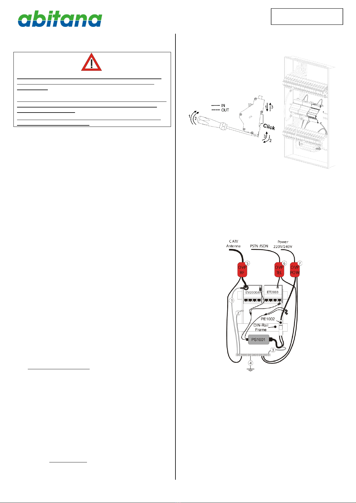
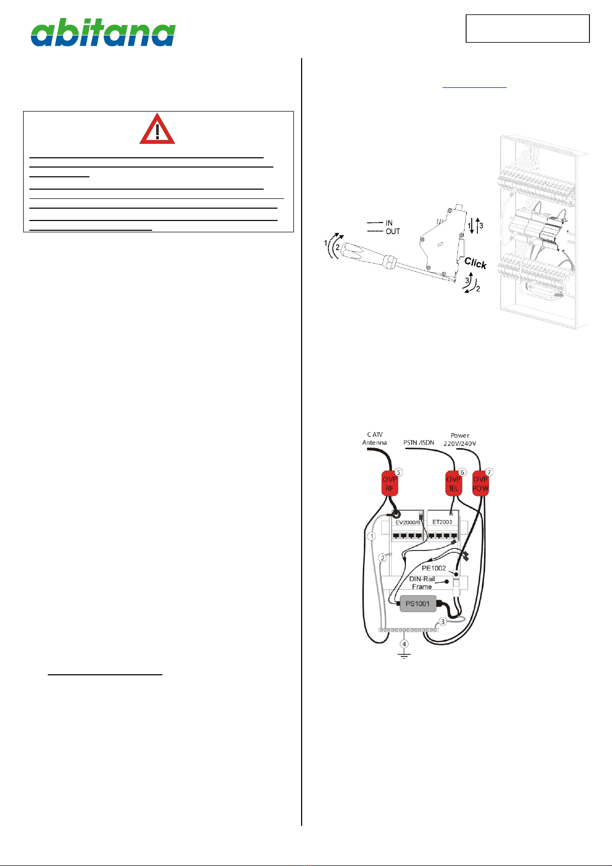
Fig1:Montage op de DINrail.
Aanbeveling inzakeoverspanningsbeveiliging
Het issterk aanbevolen omeen bijkomende overspanningsbeveiliging
teplaatsen inseriemet allebinnenkomende signalen.Ditom
beschadigingvan de installatiedoor overspanningen tevoorkomen.
Deze overspanningen kunnen veroorzaakt worden door
spanningsfluctuaties,bliksem,etc.
Per signaaltype iseen specifiekmodelvan beveiliging nodig(Antenne
/ Kabeldistributie(5), Telefoon (6),Netspanning(7)).

140507_ABI-EV20XX_QSG_ML_RevA.docx
FrançaisPage 3 N.V. abitana S.A.
FRANCAIS
ABI-EV2000S00
ABI-EV2008S00
ABI-EV2012S00
TV-sur-Paires-Torsadées
AmplificateurRF
Guide d’installation
1Contenu del’emballage
•un moduleABI-EV20XXS00
•Guide d’installation
•3Terminaisons RJ45
2Outillage
•Cléàécrou11mm
3Introduction
LesmodulesABI-EV2000S00 etABI-EV2008S00 sontdes
amplificateurs large-bande avec voiede retour intégrée. Les appareil
sont pourvusd’une entréecoaxpour leCâbleou laTNTetquatre
sortiesTVRJ45 sur lafaceavant.
L’amplificateur ABI_EV2008S00 disposeégalementde deuxsorties
coaxpour brancher desmodulesd’extension ABI-EV2014S00afinde
porter lenombre deTVsraccordées à8ou 12.
Pour leraccordement du côtédu récepteur TVil existeun nombre
d’adaptateurs (avecou sansréglage de niveau etfiltres)tels que ABI-
AC1001S00,ABI-AC1002S00,...
Les appareils sontcompatiblessurchacunedesquatre sorties avec
une voiede retour in-band Docsis (ex. VOO, UPC...)pour assurer les
servicesinteractifs deTVnumérique.
4Connecteurs
5Alimentation
Le coefficientde charge pour ABI-EV2000S00etABI-EV2008S00 =
0,6A.
Le coefficientde charge pour ABI-EV2014S00=0,0A.
Coefficient maximal(sommedescoefficients desmodulesbranchés)
pour lemoduled’alimentationABI-PS1001S14=4A.
6Installation
Mettezhorstensionl’alimentationABI-PS1001S14 du coffretcentralde
communication au moyen de l’interrupteur généralou en enlevant la
prise220Vde l’alimentation.
1.Assurez-vousque leblindagedupointdetransitionde la
télédistributionest proprementreliéàlamasse.
2.Ouvrezlecoffretcentralde communication.
3.Clipsezlemodulesur lerail-DIN(Figure 1).
4.LesmodulesABI-EV20XXS00 sont équipésd’un filde
masse(1) quiest reliéau connecteur d’entrée (Type-F). Ce
fil doit être reliéàlamassedesécuritéde l’installation. (voir
dessinci-dessous).
Lescomposantssuivantsde l’installation doiventégalement
être reliésàlamassede sécurité: lechâssisrail-DIN(2) et
l’alimentation(3)
5.Branchezune desjarretièresd’alimentation en provenance
de l’adaptateursecteur ABI-PS1001S14 au connecteur
Alimentation.
6.Connectezun câblecoaxialentrelepointd’arrivée Antenne
ou Télédistribution etleconnecteur CATV/ANTENNE
d’entrée en facehautedu module.
7.Reliezlecaséchéantlesmodulesd’extension (ABI-
EV2014S00) au moyen d’un cordon coaxauxsorties
CATV/ANTENNE.
RFIN1
PSIN
+5VDC
CATV
RP
RFOUT2 RFOUT3
CATV
RP
CATV
RP
S
e
u
l
eme
n
t
A
B
I
-
E
V
2008S0
0
TV-over-Twisted-Pair
RFamplifier -4port -Master
PS1001
CADRE Rail-DIN
PE1002
1
2
3
4
RFIN1
PSIN
+5VDC
SAT
CATV
RP
RFOUT2 RFOUT3
CATV
RP
CATV
RP
ABI-AC1001S00
ABI-AC1002S00
ABI-AC1010S00
RF IN1
PS IN
+5VDC
CATV
RP
RF OUT2 RF OUT3
CATV
RP
CATV
RP
TV-over-Twisted-Pair
RFamplifier-4port-Master
TV-over-Twisted-Pair
Slave-In-band RP TV-over-Twisted-Pair
Slave-In-band RP

140507_ABI-EV20XX_QSG_ML_RevA.docx
FrançaisPage 4 N.V. abitana S.A.
FRANCAIS
8.Serrezlesconnecteursen utilisantlaclefàécrou.
.
Si onnesuitpasrigoureusementles instructions(1) jusqu’a(7)
les modules ABI-EV2000S00 et ABI-EV2008S00 peuventêtre
endommagés
Si cen’est pas possibledemettreles rails-DIN, lechâssiset/oule
pointdetransitionCATV alamasse, il fautaumoinsles relier
entreeuxélectriquement.
Notez égalementnotreconseil ence quiconcernelaprotection
surtensionàlafindece manuel
9.Mettezlecoffretcentralde communicationsoustension.
10.Le témoinenfaceavantdoitmaintenantêtre vert.Lorsdu
démarrage,etensuitechaque minuteilclignote.SI lesignal
d’entrée est suffisantletémoinclignotera au moins5foisde
suite.
Siletémoinestrouge, iln’yapas de signalàl’entrée.
Siletémoinestjaune,lesignalàl’entrée esttrop faiblepour
pouvoirgarantirun bon fonctionnementsur lalongueur
maximaleducâblageSmartmedia(35m).Dans cecasdes
mesuressupplémentairess’imposentsur lesignald’entrée,
et lecas échéantl’opérateur doitêtre contacté.
Fermezlecoffretde communication.
11.Repérez laprisemuraleprèsdutéléviseur,de l’équipement
vidéo ou décodeur que voussouhaitezconnecter à
l’amplificateur.
12.Sicetteprisesetrouveàmoinsde15mdu coffretcentral,il
est préférablede choisirun adaptateur (BALUN) réglable
(ABI-AC1001S00).Pour leslongueurssupérieuresa15m,on
peut utiliserl’adaptateurfixe(ABI-AC1002S00).
Pour leABI-AC1001S00,mettez-leen position deniveau
maximumen tournantlavisde réglage bleue lentementdans
lesens des aiguillesd’une montre.Ne forcezpas.
Insérezlebalundanslaprisemuralechoisie.
13.Insérez un cordon coaxial(ABI-PC1006Sxx)entre lebalun et
letéléviseur.
14.Allezaucoffretcentraldecommunication etrepérezle
connecteur quicorrespond àlaprisemuraleen question.
Insérezuncôtéd’uncordonOmniMediade labonne longueur
dansceconnecteur.
15.Insérezl’autre côtédu cordon OmniMediadansun desports
TV1àTV4en faceavant de l’amplificateur.
16.Contrôlezlaqualitéd’image sur l’écran du téléviseur.Si
nécessaire,ajustezleniveau dusignalau téléviseur en
tournantlavisde réglage bleue du balun.Cecin’est
normalementnécessaire quesilaliaisonentrelecoffretet la
prisemuraledu téléviseur estcourte.
REMARQUE IMPORTANTE:
Insérezuneterminaison RJ45 dansles sorties inutilisées de
l’amplificateur.
Pourl’ABI-EV2008S00 insérezuneterminaisonFdansla/les
sorties coaxnonutilisées(2terminaisonsfournies en
standard).
Sitoutes les sorties sontreliéesavec uneprise murale,il est
préférabled’inséreruneterminaison dansles prises murales
où il n’yapas detélévisionraccordée.
On peututiliserl’adaptateurréglablecommeterminaisonsion
met l’adaptateur sur niveauminimal(entournantlavisde
réglagelentementdanslesenscontrairedesaiguillesd’une
montrejusqu’aumomentoùlavisbloque).
Voustrouverezde plusamplesinformationsau sujetde ceproduitsur
notre siteweb: www.abitana.com
Figure 1:Installation sur rail-DIN
Notrerecommandationconcernantlaprotectionsurtension
Ilestconseilléde prévoirune protectionsurtension supplémentaire sur
lessignauxexternes. Ceciprotègelesystèmecontre lessurtensions
provoquées par lesfluctuationsde latensiondu réseau oupar la
foudre.
Ilexisteuneprotection spécifiquepour chaque type designal(Antenne
/Télédistribution(5),Téléphone (6),Alimentation 220 V (7)).

140507_ABI-EV20XX_QSG_ML_RevA.docx
EnglishPage 5 N.V. abitana S.A.
ENGLISH
ABI-EV2000S00
ABI-EV2008S00
ABI-EV2014S00
TV-over-Twisted-Pair
RF amplifier
Quick StartGuide
1PackageContents
•DINrail mountableRFAmplifier modules
•QuickStartGuide
•3RJ45 Termination plugs
2Tools
•Spanner 11mm
3Introduction
The ABI-EV2000S00 andABI-EV2008S00 are RFamplifierswith
integrated returnpath.The modulesareequipped withonecoaxial
inputfor CATVsignalor DVB-Tantenna.The moduleshaveone
coaxialTVinputand 4independentRJ45 (Twisted Pair) outputson
the front.
The ABI-EV2008S00has2coaxialextensionoutputs tofeedone
or twoABI-EV2014S00 modules,bringing the capacityto8or12
TVsets.
Arange ofTwisted PairtoCoaxadapters(withor without
adjustment,filters,IR…)isavailablefor installationatthereceiver
end (i.e.ABI-AC1001S00,ABI-AC1002S00,…).
All 4portsofthe modulesare readyfor Docsiscompliantin-band
return pathproviding interactivedigitalTVservices(e.g.VOO,
UPC,…)
4Connectors
5Power
Load ratioforABI-EV2000S00 andABI-EV2008S00 =0,6A.
Load ratioforABI-EV2014S00 =0,0A.
Maximumallowed load ratio(sumof theload ratiosfor allmodules)for
powersupplyABI-PS1001S14 =4A.
6Installation
Power Off thecentral ABI-PS1001S14 Power Supplybymeansofthe
CircuitBreaker installed inthe ‘Comm CenterCabinet’,or byremoving
the mains power cord fromthe Power Supply.
1.Makesuretheshieldingofthe NetworkInterfaceUnit(NIU) or
CATVtransition pointisproperlyconnected totheprotective
ground.
2.Open the ‘Comm Center Cabinet’
3.Clickthe ABI-EV20XXS00 unit on the metalDIN-rail.
4.The ABI-EV20XXS00 issuppliedwithagrounding wire,
connectedtothe inputF-connector.
Thiswire (1) mustbe connected totheprotectiveground of
the installation.
The following systemdevicesalsoneed tobe connected to
the protectiveground:TheDIN-Rail frame(2) andthePower
supply(3)
5.Connect one oftheunused POWERconnectorsofthe ABI-
PS1001S14QuadruplePower Supply(5VDC -4A).
6.Connect acoaxcablefromthe CATVconnection point(NIU)
or the CATVtransition pointtothe coaxinputconnector
CATV/ANTENNEon thetop oftheunit.
7.If needed,connectextension modules(ABI-EV2014S00) to
the coaxialCATV/ANTENNEoutputsusingacoaxialpatch
cord.
RFIN1
PSIN
+5VDC
CATV
RP
RFOUT2 RFOUT3
CATV
RP
CATV
RP
S
e
u
l
eme
n
t
A
B
I
-
E
V
2008S0
0
TV-over-Twisted-Pair
RFamplifier -4port-Master
PS1001
DIN-Rail Frame
PE1002
1
2
3
4
RFIN1
PSIN
+5VDC
SAT
CATV
RP
RFOUT2 RFOUT3
CATV
RP
CATV
RP
TV-over-Twisted-Pair
RFamplifier- 4port-Master
ABI-AC1001S00
ABI-AC1002S00
ABI-AC1010S00
RF IN1
PSIN
+5VDC
CATV
RP
RF OUT2 RFOUT3
CATV
RP
CATV
RP
TV-over-Twisted-Pair
RFamplifier-4port-Master TV-over-Twisted-Pair
Slave-In-bandRP TV-over-Twisted-Pair
Slave-In-bandRP

140507_ABI-EV20XX_QSG_ML_RevA.docx
EnglishPage 6 N.V. abitana S.A.
ENGLISH
8.Tightenthe screws ofthe connector, using the spanner
.
Failingtofollowtheinstructions(1) to(7) inthespecifiedorder
mayleadtopermanentdamageoftheABI-EV20000S00 and ABI-
EV2008S00amplifiers
Whenitisimpossibletoconnect theDINrails,frameor CATV
transitionpointtoground,make suretheyareat leastat thesame
electricallevel(connectedtoeachother).
Please alsonote our recommendation regarding overvoltage
protectionat theendofthismanual
9.Turn on the power
10.The indicator on thefrontofthe moduleshouldlightup green.
At start up and after that everyother minute,the indicator will
blink.When the inputlevelissatisfactory,the indicator will
blink at least5times.
If the indicatoris red,there is noinput signal.
If the indicator isyellow,the inputsignalistoo lowto
guarantee proper operationwhenusing themaximumcable
lengthofthe SmartMedianetwork(35m).Inthiscaseextra
measurements ofthe inputsignalare required.
11.Closethe‘Comm CenterCabinet’.
12.LocatetheOutletnearyour TV-setordecoder youwantto
connect
13.Incasethedistancetothe‘comm centercabinet’for the
selected Outletisshorter than 15m,werecommend the use
ofanadjustableadapter(BALUN) (i.e.ABI-AC1001S00).For
distanceslonger than 15m,afixed adapter can beused (i.e.
ABI-AC1002S00).
For the ABI-AC1001S00,setthe leveltomaximumby means
ofthe power leveladjustmentscrewlocated on the balun
(Turn the screwgentlyclockwiseuntil it blocks).
14.Insertone end ofacoaxpatchcord (ABI-PC1006Sxx)intothe
Balun (ABI-AC1001S00 or ABI-AC1002S00).
15.Insert theother end ofthe Coaxpatchcord intothe TV–setor
STB.
16.Inthe ‘Comm Center Cabinet’,locatethe Comm Center
Connector thatcorrespondstothe outletwhere you just
insertedthePatchcord andinsertone end ofa‘CommCenter’
Patchcord’of asuitablelengthintothisconnector.
17.Insert the other endofthePatchcord inone ofthenumbered
ports (TV1–TV4) on thefrontoftheAmplifier.
18. Check the signalqualityon the TVset;and adjustthe levelby
meansoftheleveladjustmentscrewon the Balunif
necessary.Normallythisisonlyrequired for shortlinks
between the Comm centerCabinet and the outlet.
IMPORTANTREMARK:
InsertaRJ45TerminationPlugineveryunusedportofthe
amplifier.
Ifallfour ports areconnectedtooutlets,butnotalloutlets
have adevice (TV/HDR/…)connectedtoit,itisstrongly
recommendedtoinsertaTermination Plug intothelatter
(unused)outlets.
For theABI-EV2008S00,terminate all unusedF-connectorsby
meansofthe(supplied)F-terminators
Avariablegainbalun(RJ45/coaxadapter)canbeusedinstead
ofaTerminationPlug bysettingittotheminimumlevel
position(gentlyturn theseting screwcounterclockwise tillit
locks).
Additional,and more detailed information concerning thisproductcan
be found on the website: www.abitana.com.
Figure 1:Installation on the DIN-rail
Recommendationregardingovervoltageprotection
It isrecommended toadd an overvoltage protection tothe incoming
signals. This protectsthe systemagainstovervoltagescausedby
powersurges,lightning, etc.
Adifferenttype ofprotector is required for everytype ofsignal
(Antenna/CableTV(5) , Telephone (6) , Mains Power (7))
This manual suits for next models
2
Table of contents
Languages:
Other Abitana Amplifier manuals