Absco Industries Assembly Instruction Manual
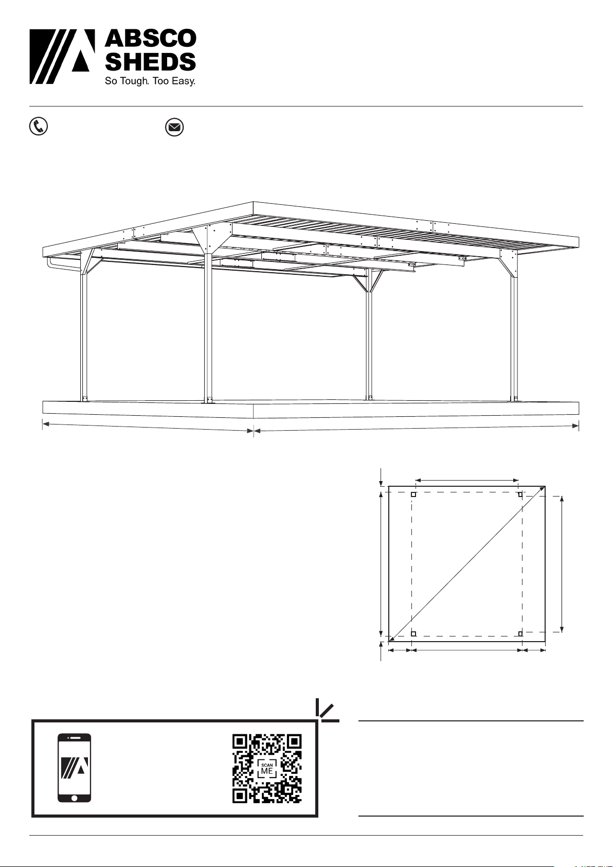
ABSCO SKILLION CARPORT
MODEL: CPDN2
5.50mW x 5.50mD x 2.37mH
Model: CPSN2 25/11/22 2
Site Preparation
• Local council approval must be obtained prior
to construction of the carport. Once you have
selected your site you will need to create
and lodge a site plan to your local council or
certifier. You will also have to attach a copy of
the engineering drawings at the back of these
instructions to your site plan.
• The site for the carport must be level, refer
to concrete and foundation notes on the
engineering drawing.
General Instructions
• Beforecommencinganyassembly,readthrough
these instructions and engineers drawings in
detail to gain a thorough understanding of
assembly methods and associated details.
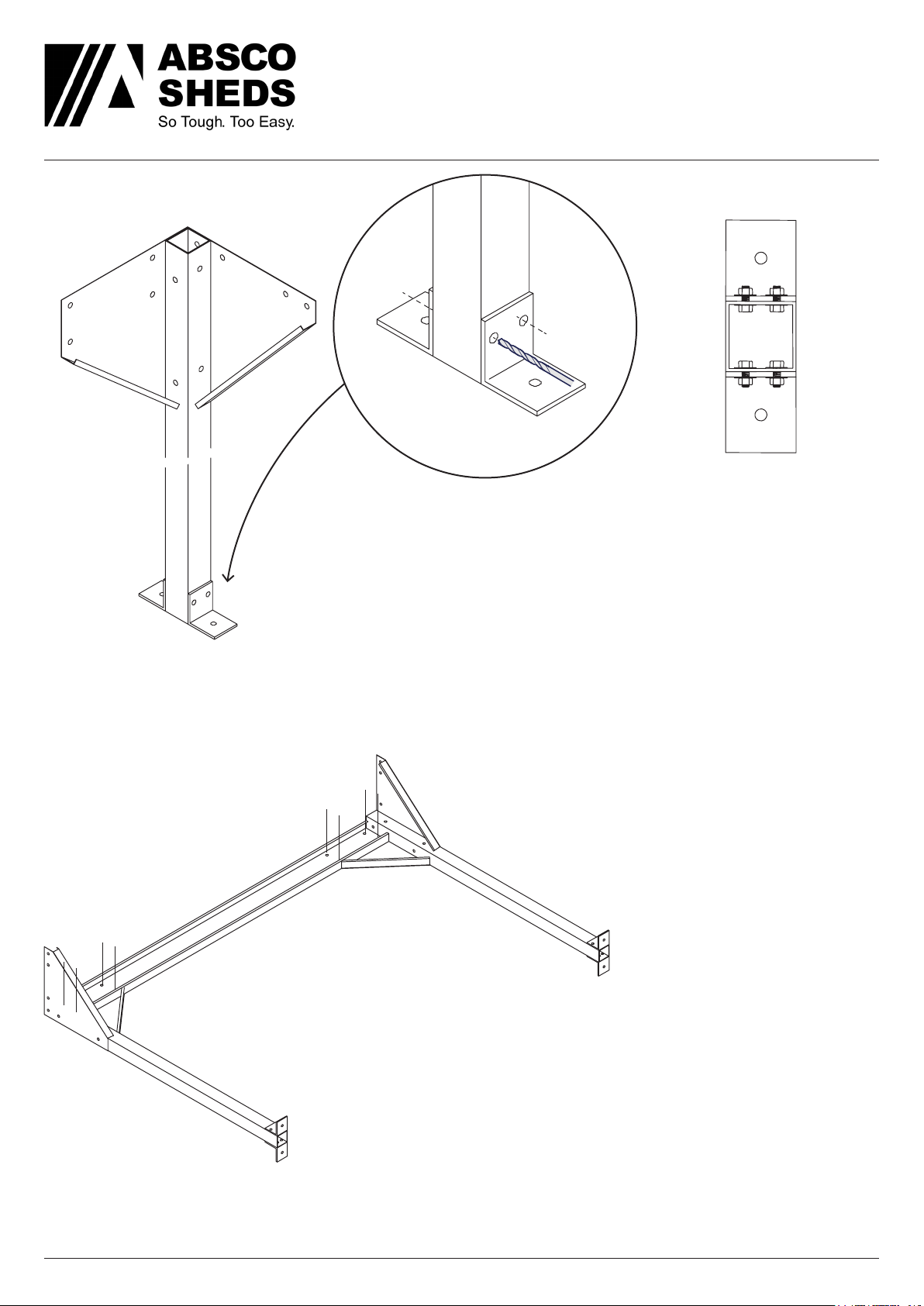
• Some components have been pre-punched.
Some 10mm holes will still have to be drilled.
It may be easier to drill a small pilot hole first.
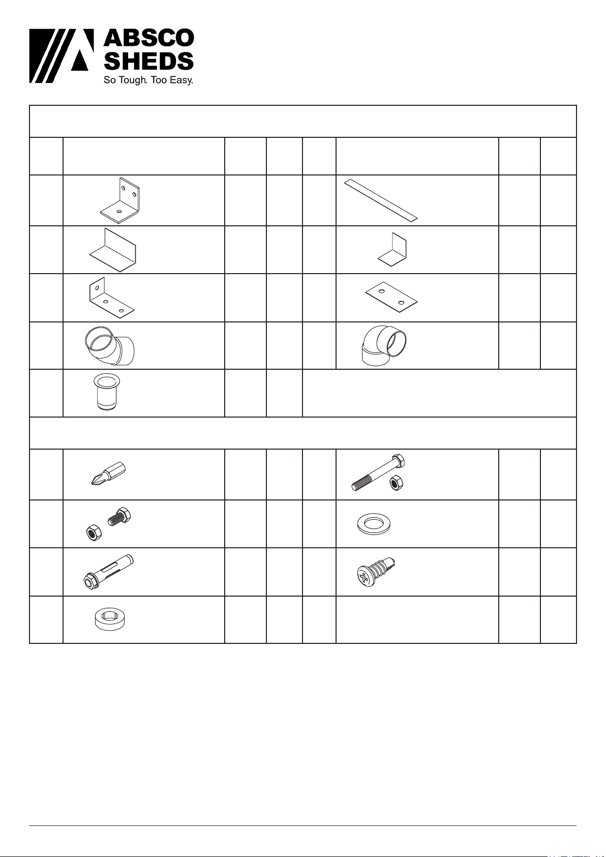
• Measure, and check off all components using
the parts lists on the following pages prior to
commencement. To prevent damage in transit,
some components may be packed inside
others, almost hidden. Carefully examine
inside each component to ensure that you
have located every item. If a discrepancy is
found, contact Absco Industries immediately.
Safety Notes
• The assembly of this product requires some
lifting of heavy objects. Two person lifts are
required.
• Some parts have sharp edges and/or corners.
The use of gloves and safety shoes is highly
recommended. Pay attention to where these
parts can be safely handled, and plan the
handling of these parts before working with
them.
• Drilling sheet metal produces small metal
shavings the use of safety glasses and the
periodic clearing of these shavings throughout
the build is recommended.
• Use the appropriate personal protective
equipment for any tool used during the
assembly.
Tools Required
• Electric drill with chuck
• 3 and 10 mm drill bits
• Hammer drill
• 10 mm masonry drill bit
• Mallet
• ‘G’ clamps
• Tape measure
• Socket set
• 17 mm spanner / shifter
• Spirit level
• Water proof sealant (silicone)
• 1.8m ladder
• PVC solvent welding cement.
BEFORE STARTING ASSEMBLY