AbsolutAire UC-3 User manual

UC-3
User Guide
© 2022 AbsolutAire, Inc.
010622
HTLV

A Note About Custom Designs
AbsolutAire often builds equipment with special features as requested by
the customer. This manual only covers standard features and does not
include any changes made for special feature requests by the customer.
010622

Table of Contents
Images
Warning 1
HMI Screen Information 3
Sensor Alarm Display 4
A Note About Custom Designs 1
Introduction 3
Operation 3
Schedule 5
Menu Tree 7
Main Display 7
Quick Access 7
Set Points 7
Status 7
Schedule 8
Alarms 9
Config 10
Advanced Menu 10
Network Integration 11
Tables
Network Points List 12
010622

Introduction
The Smart-Vue User Interface (UI) for the UC-3 HTLV Control System
displays the information necessary to operate and diagnose the Heating
and Ventilating Unit.
This is connected to the controller via a CAT-5E cable with a maximum
length of 600 feet.
HMI Screen Information
At the top left corner of the display there is a bell symbol. This is the system
alarm indicator. If an alarm is present in the unit this indicator will blink. If no
alarm is present this indicator will not be visible.At the top right of the
display is instructions for turning the unit on/offas well as menu/sub-menu
options names. When navigating the menu, the menu title will be displayed
here. Across the center of the display is the data with the units of measure.
The system is capable of displaying up to 4 decimal places. At the bottom
left is the fan status. In the bottom center is the mode of operation and at
the bottom right is the occupancy status.
Three buttons are available for operation (see cover page). The center
button allows you to access the menu and scroll through the menu items.
The up/down buttons are used to change values.
Operation
The system displays the current Space Temperature when idle. The menu
is separated into sub-menus for ease of use, and only the options the unit
is equipped with will be displayed. When navigating the menu blinking
items are set points that can be changed, while non-blinking items are
status objects which can be viewed only.
010622

To turn the unit on or off, press the “up arrow” to access the Fan Command.
Use the “up arrow” to select the desired option, then press the center
button “menu” to return to the main display.
To change set points such as temperature or building pressure, press the
“menu” button until you see “SET POINTS” in the top right of the screen.
Press the “up arrow” to enter this sub-menu. Your first choice will be
“mode”. Use the up arrow to select “heat or vent” (unless the unit has air
conditioning, in which case the choices will be “heat/cool/air”). When you
have made your choice, press the “menu” button to move to the next menu
item, which will be the Occupied Set Point. Again, use the “up/down” arrow
buttons to make your entry and press “menu” when finished. Continue
scrolling through the Set Points sub-menu until all of your desired settings
are completed. When scrolling the menu and you see the option “BACK” in
the top right, pressing the “up arrow” will take you to the previous menu.
Scrolling through the “STATUS” sub-menu will allow you to view the status
of all of the unit sensors and burner operation. This is useful for checking
unit operation or outdoor conditions.
The “ALARMS” menu will only be displayed if there is a system alarm, as
indicated by the blinking alarm bell on the display. When an alarm is
present, scrolling through this sub-menu will allow you to view the alarm(s)
in “plain English” enumerated text. This is useful for diagnosing the unit in
the event of a problem.
Sensor Alarm Display
010622

The “SCHEDULE” will be described later. This is a 7-day occupancy
schedule used for the purpose of temperature or operation changes during
unoccupied times.
The “CONFIG” menu is where the primary operating set points for the unit
are set such as the minimum and maximum allowable discharge
temperatures, as well as other items. Again, use the “menu” button to scroll
through the sub-menu and the “up/down” buttons to edit your selection.
Schedule
010622
The programmable 7-day occupancy schedule has the ability to set
occupied and unoccupied times for a standard week, as well as five
individually programmable special events which will override the weekly
schedule.
The special event programming monitors the current year, as well as the
month being programmed, to prevent invalid days from being programmed
as a special event (for example April 31
st
or February 30
th
). The system also
monitors for leap years so February can have either 28 or 29 days
programmed.
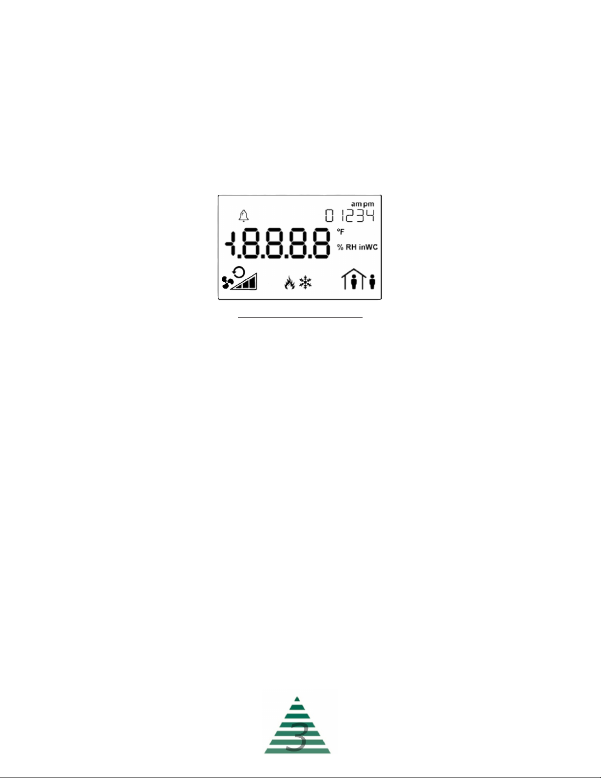
Occupancy status is indicated by the occupancy icon in the lower right
corner of the HMI screen. A steady icon indicates the system is following
the standard 7-day schedule, while a blinking icon indicates the system is
following a day programmed as a special event.
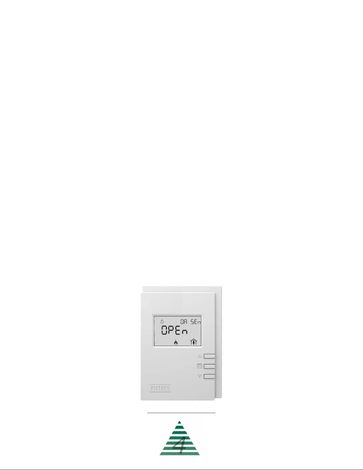
To program the 7-day schedule, press the “menu” button until
“SCHEDULE” appears in the top right of the display. Press the “up arrow”
to enter the schedule.
The first section is the “WEEKLY SCHEDULE”. Press the “up arrow” to
enter the weekly schedule. Select the “DAY OF WEEK” to be programmed,
with Monday being Day 1. Press “menu” to navigate to “OCC HOUR”. Use
the up/down arrows to select the occupied hour, in 24-hour format, and
press “menu” to confirm. Press “menu” again to navigate to “OCC MINUTE”
and use the up/down arrows to select the occupied minute and press
“menu” to confirm. Continue to set the “UNOC HOUR” and “UNOC
MINUTE” for this day, then select the next day to program. Leaving the
hours and minutes set to “0” for a day will leave that day un-programmed
and the system will assume an occupied status for that day.
When finished with the WEEKLY SCHEDULE select “BACK” to return to
the menu and program SPECIAL EVENTS if desired.

Special events are used to override the weekly schedule and either keep a
facility occupied for an event such as inventory or an important meeting, or
to keep a facility unoccupied on a holiday when the building will remain
empty.
To program special events, press the “menu” button until “SCHEDULE”
appears in the top right of the display. Press the “up arrow” to enter the
schedule.
Press “menu” until “SPECIAL EVENTS” appears in the top right of the
display. Press the “up arrow” to enter the special event programming menu.
Special events are programmed based on the month and day of the month
you wish to program as a special event. Leaving a month and day set to “0”
will leave that event un-programmed.
The first option will be the “EVENT NUMBER”. Select the event desired
event number (1 - 5) and press “menu” to navigate to “EVENT MONTH”.
Select the desired month (1 - 12) and press “menu” to confirm. Press
“menu” to navigate to “EVENT DAY”. Select the desired day of the month
(1 - 28/29/30/31 as allowed) and press “menu” to confirm.
Press “menu” to navigate to “OCC HOUR”. Select the occupied hour/
minutes as well as the unoccupied hours/minutes in the same fashion as
programming the weekly schedule.
When finished, either select the next event number to be programmed, or
select “BACK” to return to the previous menu.
To remove a special event, set the event month and day to “0”.
Once the schedule is set, the unit will follow the occupied and unoccupied
temperature set points for each day as well as any special events.

Menu Tree
Main Display
Space Temp [AV33] R
– Current space temperature at the User
Interface (or remote space temperature sensor if equipped).
Quick Access
Fan Command [MSV51] R/W
– This is accessed by pressing the “up
arrow” from the main screen and is used to turn the unit ON and OFF. The
unit will cycle on and offto maintain space temperature by supplying the
temperature of air defined in the CONFIG menu.
Set Points
Mode [MSV53] R/W
– This is the mode of operation. Select “Heat” or
“Vent” as desired (if the unit has cooling installed the choices will be “Heat/
Cool/Air”)
Occ Set Point [AV51] R/W
– Occupied Heat Set Point.
Unoc Set Point [AV52] R/W
– Unoccupied Heat Set Point (only
available if the unit has scheduling as an option).
Burner Reset [MSV54] R/W
– Burner reset command for use during
a burner lockout alarm. This is an “on/_on_” toggle selectable via the “up
arrow” button.
Status
Space Temp [AV33] R
– Current space temperature at the User
Interface (or remote space temperature sensor if equipped).
Outside Temp [AV34] R
– Current outside air temperature.
Discharge Temp [AV35] R
– Current discharge air temperature.
Heat Command [AV32] R
– Current command (0% - 100%) issued
to the burner for heat.
010622
When viewing menu tree options, the standard convention is:
Point Name
(as listed on the HMI)
[BACnet ID] R
or
R/W
(read only or
read/write).
Example:
Space Temp [AV33] R

Schedule
(only visible if the unit has scheduling)
Manual Occupancy
- Allows the ability to force Occupied or
Unoccupied modes, or to have the system follow the programmed
schedule.
Weekly Schedule
Day of Week
– Schedule day to be programmed.
Occ Hour
– Occupied hour to be programmed. This is the hour (in 24
hour format) that the unit will assume occupied status.
Occ Minute
– Occupied minute to be programmed. This is the minute
of the hour the unit will assume occupied status.
Unoc Hour
– Unoccupied hour to be programmed. This is the hour
(in 24 hour format) that the unit will assume unoccupied status.
Unoc Minute
– Unoccupied minute to be programmed. This is the
minute of the hour the unit will assume unoccupied status.
Special Events
Event Number
- The schedule supports up to five special events.
This is the event number to be programmed
Event Month
- Month of the year the special event is in.
Event Day
- Day of the month the special event is on.
Occ Hour
– Occupied hour for the special event. This is the hour (in
24 hour format) that the unit will assume occupied status.
Occ Minute
– Occupied minute for the special event. This is the
minute of the hour the unit will assume occupied status.
Unoc Hour
– Unoccupied hour for the special event. This is the hour
(in 24 hour format) that the unit will assume unoccupied status.
Unoc Minute
– Unoccupied minute for the special event. This is the
minute of the hour the unit will assume unoccupied status.
010622

Alarms
(alarm menu is only visible if an alarm is present)
Space Sensor [MSV8] R
– Space sensor alarm status. Enumerated
“no-fault/open/short”. Check sensor wiring.
Outside Sensor [MSV9] R
– Outside sensor alarm status.
Enumerated “no-fault/open/short”. Check sensor wiring.
Discharge Sensor [MSV10] R
– Discharge sensor alarm status.
Enumerated “no-fault/open/short”. Check sensor wiring.
Burner Lockout [MSV12] R
– Burner lockout alarm status. Indicates
the burner failed to light when requested. Enumerated “normal/lockout”.
Low Temp Alarm [MSV14] R
– Low temperature lockout alarm. This
is an indication that the unit was discharging air colder than the “Low Temp
Alarm” setting in the “Config” menu for greater than “Low Temp Time”
minutes. Check the burner for proper operation.
Dirty Filter [MSV13] R
– Dirty filter indication (only available if the
unit has dirty filter monitoring as an option).
Motor Alarm [MSV11] R
– Motor not responding alarm status. This
indicates the unit was enabled and the supply fan motor failed to start
within two minutes. Check VFD or overload (as available), OA damper limit
switch and wiring, and power.
Burner Response [MSV6] R
- Indicates the burner was commanded
to light and the controller did not receive confirmation.
Burner Watchdog [MSV7] R
- Indicates the burner did not reach the
requested discharge temperature within 5 minutes. Possible problem with
gas pressure or gas valves.
Hardware Override [MSV1 - MSV5] R
- Indicates a hardware point
was overridden by the building management system. As all control points
are available to the network, overrides are unnecessary. Remove the
override to clear the alarm.
010622

010622
Config
Heat Lockout [AV59] R/W
– Heating mild weather stat setting. When
the outside or mixed air temperature is above this setting the burner will be
automatically disabled (only available if the unit has mild weather stat as an
option).
Control Deadband [AV58] R/W
- Space temperature deadband for
cycle on/offcontrol.
Discharge Set Pt [AV53] R/W
- Discharge temperature set point for
heating mode.
Min Discharge [AV54] R/W
– The units minimum allowable
discharge temperature.
Max Discharge [AV55] R/W
– The units maximum allowable
discharge temperature.
Low Temp Set Pt [AV56] R/W
– If the unit discharges air below this
temperature set point for “Low Temp Time” minutes it will shut down and
close the isolation dampers (Only available if LTL is available).
Low Temp Minutes [AV57] R/W
– The time delay (in minutes) for the
“Low Temp Alarm” (Only available if LTL is available).
Advanced Menu
(Press and hold “menu” button for 5 seconds to enter)
Date Time
Year
– Set the real time clock year.
Date
– Set the real time clock date.
Time
– Set the real time clock time.

010622
The controller in this unit can easily be integrated into a BACnet MS/TP
Building Management System. The controller will automatically detect the
baud rate of the network it is connected to after a power cycle, and will
automatically begin communications.
The MAC Address is set via the dip switches on the front of the controller.
When shipped, each unit will have a factory default MAC address with
multiple units for the same project having incremented MAC addresses.
The dip switches are numbered 1 through 8, with 1 being the LSB. The
numbering is standard binary format (switches 1 and 3 ON equals an
address of 5).
The Network Instance Number (device instance) is automatically
configured based on the MAC Address setting. The network instance
number will always be 3640+(MAC Address). For example, if the MAC
address is set to 25 the network instance number would be 364025. In the
event of a duplicate instance number on the network, simply change the
MAC address to change the instance number.
The following page has a complete listing of the BACnet points with their
descriptions.
Network Integration

010622

(This page intentionally left blank for notes)
010622
Other manuals for UC-3
1
Table of contents
Popular Thermostat manuals by other brands

Habitat
Habitat HTE-01 Installation & Pairing Manual

Honeywell
Honeywell Prestige 2.0 IAQ installation instructions

Uponor
Uponor Smatrix Move Installation and operation manual

EUROSTER
EUROSTER 4040TXC6 Installation and operation manual

Venstar
Venstar Residential T7900 Owner's manual & installation guide

PSG
PSG FP700 Owner's instructions