Abstract Data ADE-60 User manual

© Abstract Data Ltd. http://www.abstractdata.biz Version 1.1.0
ADE-60 4:4 MIX UTILITY
4-Channel, Cascading, Mix & CV Utility with user-configurable
options for Attenuversion, Gain, Biasing & CV.
USER GUIDE

INTRODUCTION:
1) Module Overview Main module features in brief
2) Front Panel Front panel hardware controls and connections
3) Rear Connections Rear panel power connectivity and precautions
4) Quick Start Your first patch
OPERATION:
5) Inputs & Outputs Sockets and input/output cascading functionality
6) Knobs Knob functions
7) Jumper Connections Activating per-channel user settings
FEATURES:
8.1) User Settings: Attenuversion Attenuversion activation and functionality
8.2) User Settings: Gain Gain activation and functionality
8.3) User Settings: Bias & CV Bias and CV output activation and functionality
9.1) Patch Example 1 Basic 4-input / 1-output mixer
9.2) Patch Example 2 Attenuator, attenuverter & sub-mixer
9.3) Patch Example 3 Dual bias/offset & attenuator
9.4) Patch Example 4 Multi-function mix and voltage utility
SPECIFICATIONS:
10) Specs Hardware and power spec, credits and version info
Contents
© Abstract Data Ltd. Version 1.1.0

• The ADE-60 is a user-configurable, signal mixing and Control Voltage (CV) utility module.
• The signal path is Direct Current (DC) coupled so it will work in the same way with all signals
in the Eurorack environment including CV, Gates, Low Frequency Oscillators (LFO),
Envelope Generators (EG) and audio signals like Voltage Controlled Oscillators (VCO).
• Each channel has individual options for Attenuversion, Gain, Bias/Offset and manual CV output.
>> For more information on user settings see Sections 8.1, 8.2 and 8.3
• Each of these options can be turned on or off for each of the 4 channels, using simple, rear-panel
jumper connections, allowing users to create a module configuration that suits their own requirements.
>> For more information on jumper connections see Section 7
• The module can be used in any combination from a single 4-input / 1-output summing mixer to
4 individual 1-input / 1-output attenuators or as a mix of signal mixers, attenuators and voltage sources.
>> For more information on patch examples see Sections 9.1, 9.2, 9.3 and 9.4
• The mixer configuration is ‘cascading’ – plugging a patch cable into any output socket outputs
the summed mix of the signal at that channel and all previous channels without connected output
sockets and also removes those signals from all outputs that follow it.
>> For more information on inputs and outputs see Section 5
• Used in conjunction with the Attenuversion or Gain options – the Bias/Offset and CV option provides
a manual voltage output in the following ranges on any and/or all outputs: 0-5V; 0-10V; +/-5V; +/-10V.
>> For more information on user settings see Sections 8.1, 8.2 and 8.3
• The module is supplied with 2 sets of knobs – 4 grey and 4 blue to allow the user to visually identify
different configurations and combinations of functionality via the front panel.
• The ADE-60 is capable of outputting both high-gain audio signals and DC voltage signals – please take
care not to damage speakers, headphones – or ears! – with configurations that use these signal types.
© Abstract Data Ltd. Version 1.1.0
1) Module Overview
Page 1 of 15

Page 2 of 15
VOLUME: 1Sets the volume and the level of active user setting options for channel 1
IN: 1Signal input for channel 1
OUT: 1Signal output for channel 1
VOLUME: 2 Sets the volume and the level of active user setting options for channel 2
IN: 2Signal input for channel 2
OUT: 2Signal output for channel 2 and mix of signals from previous cascaded channels
VOLUME: 3Sets the volume and the level of active user setting options for channel 3
IN: 3Signal input for channel 3
OUT: 3Signal output for channel 3 and mix of signals from previous cascaded channels
VOLUME: 4Sets the volume and the level of active user setting options for channel 4
IN: 4Signal input for channel 4
OUT: 4 Signal output for channel 4 and mix of signals from previous cascaded channels
© Abstract Data Ltd. Version 1.1.0
2) Front Panel

Page 3 of 15
POWER CONNECTION: 10-16 pin Eurorack power connection
CH1 USER SETTING JUMPERS: On/Off jumpers for channel 1: Attenuversion Gain Bias
CH2 USER SETTING JUMPERS: On/Off jumpers for channel 2: Attenuversion Gain Bias
CH3 USER SETTING JUMPERS: On/Off jumpers for channel 3: Attenuversion Gain Bias
CH4 USER SETTING JUMPERS: On/Off jumpers for channel 4: Attenuversion Gain Bias
© Abstract Data Ltd. Version 1.1.0
3) Rear Connections
RED STRIPE
POWER CABLE
PRECAUTIONS: ONLY CONNECT THE POWER CABLE TO THE POWER CONNECTION AS SHOWN!
DO NOT CONNECT THE POWER CABLE TO ANY OTHER PORT!
The ADE-60 uses the Doepfer standard for power connection and cable orientation.
The RED stripe on the supplied power cable connects to the NEGATIVE (-12V) rail
on the ADE-60 with the RED stripe facing DOWN. This is marked on the back of
the ADE-60 PCB as “– RED”.
The ADE-60 has diode and polyfuse protection built in but an incorrectly connected
cable may still cause permanent damage to the module or the power supply.
The rear panel of the ADE-60 has exposed parts and connections. Please ensure
when handling the ADE-60 that the unit is held by the sides of the front panel or
the sides of the PCB (Printed Circuit Board).
-RED

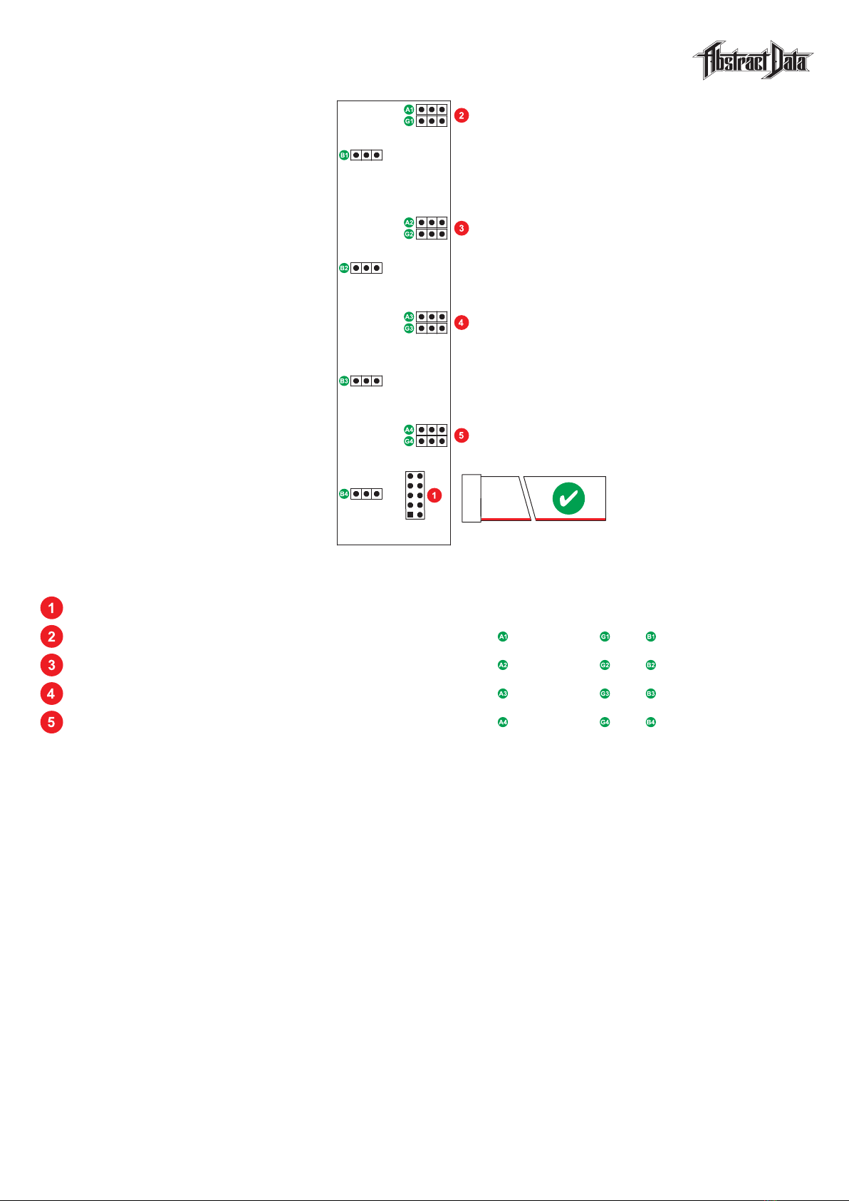
1) BEFORE INSTALLATION
Looking at the back of the module, check that all 12 (4 sets of 3) black plastic jumper connectors
are fitted on the two left-hand pins of each of the 3-pin header connectors.
All 12 jumpers are now in the off position and none of the channels will have Attenuversion, Gain
or Bias/Offset and CV options active.
Once this has been checked – the module can be installed into your rig and powered up as normal.
>> For more information on jumper connections see Section 7
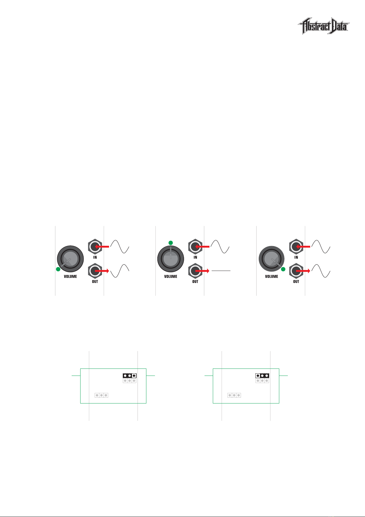
2) SET UP A 1-INPUT / 1-OUTPUT ATTENUATOR
Turn all 4 knobs fully counter-clockwise (fully left).
Connect a Eurorack audio signal, e.g. the output of a VCO, to IN:1 and connect OUT:1 to a device
that will let you safely listen to the signal using speakers or headphones.
Turn the VOLUME:1 knob clockwise (towards the right). You should hear the volume of the output
signal increase from silence (100% attenuation) at the fully counter-clockwise position to ‘unity gain’,
where the output signal is the same volume as the input, at the fully clockwise (fully right) position.
>> For more information on knob functionality see Section 6
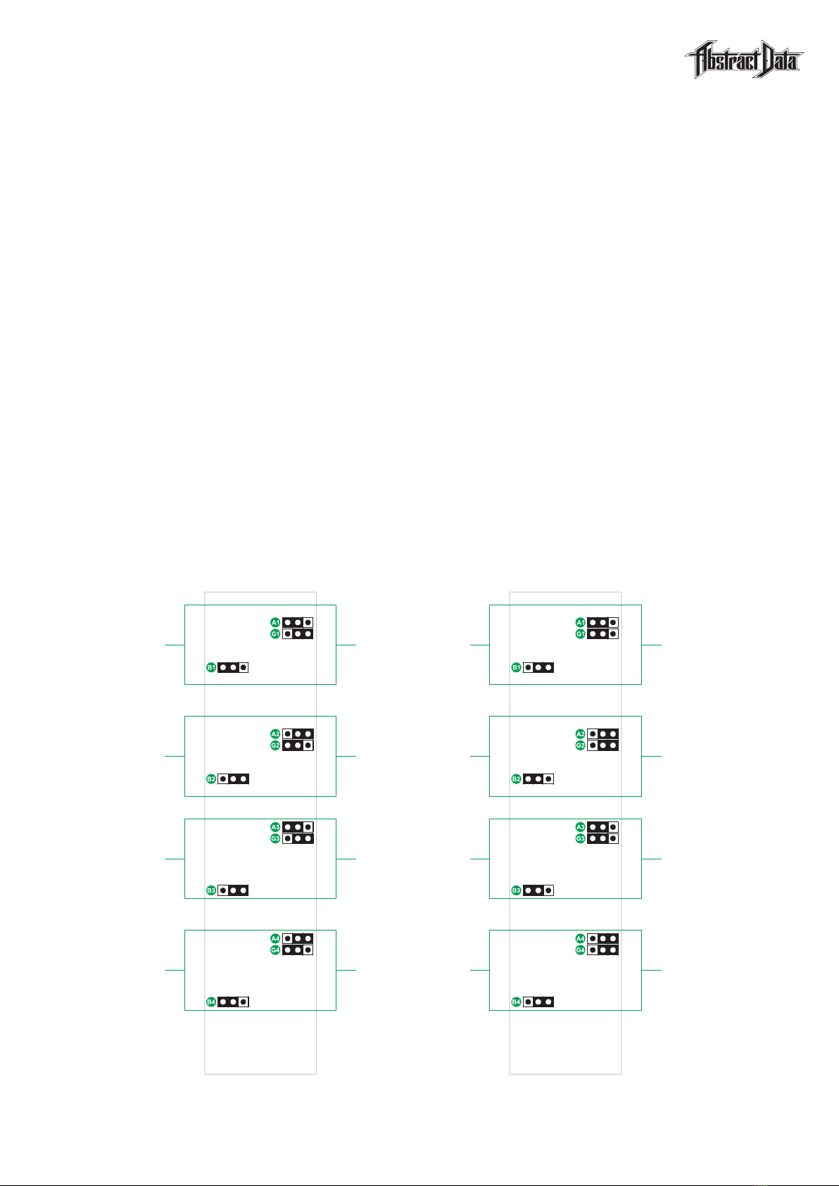
3) SET UP A MULTI-INPUT / 1-OUTPUT MIXER
Turn all 4 knobs fully counter-clockwise.
Connect a Eurorack audio signal (as described in Step 2) to IN:1, connect a different audio signal
to IN:2 and connect OUT:2 to an output device (as described in Step 2).
Turn the VOLUME:1 knob towards the 12 o’clock position (centre) – you should now hear the input
signal at IN:1.
Turn the VOLUME:2 knob towards the 12 o’clock position – you should now hear a mix of the input
signals at IN:1 and IN:2.
Leave the two volume knobs where they are, disconnect the patch cable at OUT:2, re-connect
it at OUT:3 and now patch from OUT:2 to IN:3.
This configuration gives you independent control of the mix level of the input signals via VOLUME:1
and VOLUME:2 but also gives you a ‘master volume’ control of the entire mix via VOLUME:3.
>> For more information on patch examples see Sections 9.1, 9.2, 9.3 and 9.4
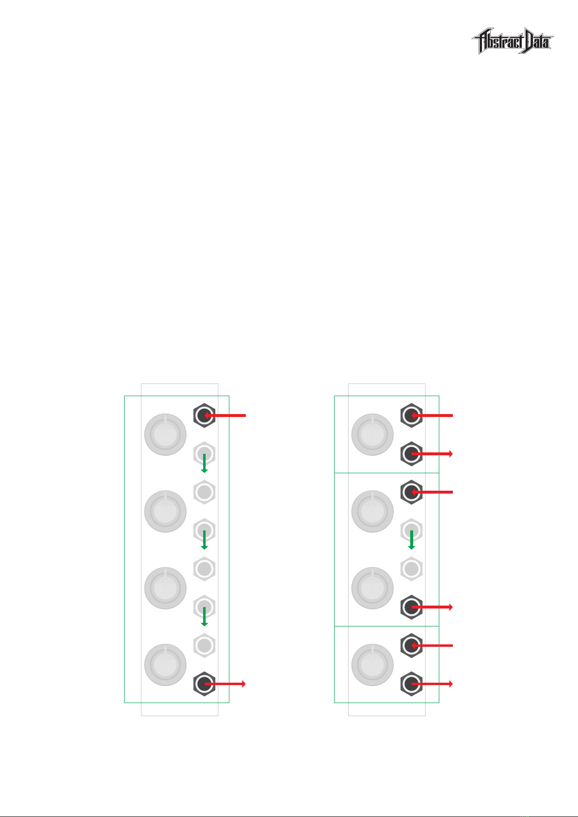
4) ACTIVATE ONE OF THE USER SETTING OPTIONS
Power down the module and carefully remove it from the case it’s installed in – trying, where possible,
to handle the module by the front panel rather than the PCB.
Each ADE-60 channel has options for Attenuversion, Gain and Bias/Offset and CV output and each
of these 3 options can be turned on or off individually using jumper connectors.
Holding the module so you’re looking at the rear PCB, carefully remove the top jumper (A1) from
the left 2 pins on the header connector and then carefully re-connect it over the right 2 pins.
By moving this jumper from the left off position to the right on position – you have turned on
Attenuversion on for channel 1.
Once the module is re-installed into your rig and powered up as normal – channel 1 will have
Attenuversion active and channels 2, 3 and 4 will continue to operate as normal attenuators.
>> For more information on user setting options see Sections 8.1, 8.2, 8.3
© Abstract Data Ltd. Version 1.1.0
4) Quick Start
Page 4 of 15

1) IN: 1-4
The ADE-60 has 4 inputs – 1 for each of the 4 mixer channels.
All inputs and the entire internal signal path is DC-coupled and will work with all standard signals
in the Eurorack environment from DC voltages and CV to audio signals.
2) OUT: 1-4
The ADE-60 has 4 outputs – 1 for each of the 4 mixer channels.
The module’s internal routing is cascaded – so an input signal at any channel (e.g. CH1) will appear
at that output and all outputs that follow it (e.g. CH2, 3, 4) until the signal reaches a channel that has
its output socket connected to a patch cable.
An output socket that is connected to a patch cable will output the summed signal of its own channel
and all previous channels with patched inputs but unpatched outputs.
This cascading design allows for any configuration from a single 1-input / 1-output summing mixer
to 4 individual 1-input / 1-output attenuators or any combination in between.
Cascading is also used in patches that require 2 channels to implement e.g. the bias and attenuation
combo that uses 1 channel (e.g. CH1) for the bias/offset and one (e.g. CH2) for attenuation.
>> For more information on patch examples see Sections 9.1, 9.2, 9.3 and 9.4
3) SIGNAL CASCADING
© Abstract Data Ltd. Version 1.1.0
5) Inputs & Outputs
Page 5 of 15
Signal 1: IN
Signal 1: OUT
Signal 3: IN
Signal 3: OUT
Internal signal cascading
example 2
Signal 2: IN
Signal 2: OUT
Signal 1: IN
Signal 1: OUT
Internal signal cascading
example 1

1) VOLUME: 1-4
Each knob provides manual control over the increase or decrease (attenuation) in volume
of the signal at that channel’s output.
This can be the input signal at that channel’s input e.g. for a 1-input / 1-output attenuator
or the summed signal of that channel’s input plus any previous inputs. e.g. for a 4-input / 1-output
summing mixer.
Each knob can also provide alternate functionality when any of the 3 user-configurable settings
are activated.
This functionality includes control over Attenuversion (non-inversion or inversion of input signals),
Gain (amplification of input signals), Bias/Offset (negative or positive offset of input signals) or CV
output (manual output of DC voltages).
>> For more information on user settings see Sections 8.1, 8.2, 8.3
© Abstract Data Ltd. Version 1.1.0
6) Knobs
Page 6 of 15

1) CONNECTORS 1-12
Each of the 4 channels of the ADE-60 have 3 user setting options: Attenuversion, Gain and Bias.
Each of these 3 user settings, per channel, can be turned on or off using the black plastic jumper
connector fitted to the 3-pin headers on the rear of the module. The jumpers operate independently
– moving 1 jumper only affects that 1 user setting.
Looking at the rear of the module you will see 4 sets of 3-pin headers – that’s 1 set of 3-pin headers
for each of the user setting options for each of the 4 mixer channels.
Each of the headers has a black plastic jumper connecting 2 of the 3 pins for each of the headers.
When a jumper connector is on the left-hand side of a 3-pin header – that user setting option
is off and when a jumper connector is on the right-hand side of a 3-pin header that user setting
option is on.
Individual user settings are turned on by carefully removing the black plastic jumper from the left side
of the header where it connects the left-hand and middle pins and replacing it on the right side so the
jumper connects the middle and right-hand pins.
You can turn as many user setting options on or off as you require, at any time and in any order and
you can combine multiple user settings across channels to create your own custom mixer configuration.
If you’re using individual channels e.g. as a single 1-input / 1-output attenuator – then the user setting
options will work only on that channel but if you’re using multiple channels then some user settings
e.g Bias – can be used to interact with other channels.
>> For more information on user settings see Sections 8.1, 8.2, 8.3
2) CONNECTION EXAMPLES
© Abstract Data Ltd. Version 1.1.0
7) Jumper Connections
Page 7 of 15
CH1
Attenuversion
Gain
Bias
CH2
Attenuversion
Gain
Bias
CH3
Attenuversion
Gain
Bias
CH4
Attenuversion
Gain
Bias
User settings example 1 User settings example 2
(A1) Off
(G1) On
(B1) Off
(A2) On
(G2) Off
(B2) On
(A3) Off
(G3) On
(B3) On
(A4) On
(G4) Off
(B4) Off
(A1) Off
(G1) Off
(B1) On
(A2) On
(G2) On
(B2) Off
(A3) Off
(G3) Off
(B3) Off
(A4) On
(G4) On
(B4) On

1) OVERVIEW
Attenuversion combines ‘Attenuation’ – the control of an input signal’s volume – and ‘Inversion’
– a reversal in the polarity of an Alternating Current (AC) waveform.
This user setting converts the functionality of a normal volume knob that controls the attenuation
of a single, non-inverted, waveform where fully counter-clockwise (fully left) outputs silence
(100% attenuation) and fully clockwise (fully right) outputs maximum volume – to one that controls
the attenuation of both a non-inverted and an inverted version of the waveform.
When this setting is activated the knob rotation starts at fully counter-clockwise with the inverted
version of the input signal output at full volume, then, as the knob rotates clockwise, it decreases
the volume of the inverted version of the input signal to silence (100% attenuation) once it reaches
the 12 o‘clock (middle) position.
As the knob continues to rotate past 12 o’clock it starts to increase the volume of the non-inverted
version of the input signal, reaching maximum volume at the fully clockwise position.
The Attenuversion user setting is activated via the 3-pin header on the rear PCB that is marked ‘Ax’
where ‘x’ is the channel number e.g. the header marked A1 is the Attenversion header for channel 1.
>> For more information on jumper connections see Section 7
2) KNOB SETTINGS
© Abstract Data Ltd. Version 1.1.0
8.1) User settings: Attenuversion
Page 8 of 15
(Ax)
Attenuversion
Jumper position
for Attenuversion (Off)
Knob at counter-clockwise
outputs inverted signal
Jumper position
for Attenuversion (On)
Left = Off Right = On
Knob at clockwise
outputs non-inverted signal
Knob at 12 o’clock
outputs silence
3) JUMPER SETTINGS

1) OVERVIEW
Gain is generally described as the ‘input volume’ of a signal going into a circuit like a mixer
or a pre-amplifier.
In the context of the ADE-60 this setting refers to the increase in volume, or the ‘gain’,
in amplitude of that signal between the input and the output.
This user setting can increase the output of a signal by up to 2x – i.e. up to 2x Gain.
When this setting is activated, at full volume, a +/-5V AC waveform will output at +/- 10V,
a +5V DC input will output at +10V and a -5V DC input will output at -10V.
When this setting is activated, the volume knob at the fully counter-clockwise (fully left) position outputs
silence (100% attenuation), rotating clockwise to the 12 o’clock (middle) position outputs ‘unity gain’
where the volume of the output equals the volume of the input and a fully clockwise (fully right) knob
position outputs a signal that is twice the amplitude (for AC waveforms) or twice the voltage
(for DC voltages) of the original input signal.
The Gain user setting is activated via the 3-pin header on the rear PCB that is marked ‘Gx’
where ‘x’ is the channel number e.g. the header marked G2 is the Gain header for channel 2.
>> For more information on jumper connections see Section 7
2) KNOB SETTINGS
© Abstract Data Ltd. Version 1.1.0
8.2) User settings: Gain
Page 9 of 15
(Gx)
Gain
Jumper position
for Gain (Off)
Jumper position
for Gain (On)
Left = Off Right = On
Knob at counter-clockwise
outputs silence
Knob at clockwise
outputs 2x gain
Knob at 12 o’clock
outputs unity gain
3) JUMPER SETTINGS

1) OVERVIEW
Bias or ‘offset’ refers to changing the voltage value at the point where a signal starts or resets.
In Eurorack, it is often used to change AC waveforms with positive and negative-going voltages
to DC waveforms for use as modulation sources for modules that require only positive voltages
as their CV input e.g. 0-5V.
Please note – this user setting changes functionality based on whether the input or the output
of an activated channel are connected or unconnected.
When this setting is activated, if the input socket is connected – the Bias functionalty is bypassed.
When this setting is activated, if both the input and output sockets are not connected – the volume
knob for this channel (e.g CH1) controls the amount of offset for all following channels (e.g CH2, 3, 4)
until the signal reaches a channel where an output socket is connected.
When this setting is activated, if the input socket is not connected and the output socket is connected
– the volume knob will control the output of a DC voltage at that output between 0-5V.
When this setting is activated in conjunction with the Attenuversion user setting it provides both
positive (≤ +5V) and negative (≥ -5V) offsets or output voltages.
When this setting is activated in conjunction with the Gain user setting it provides offsets or output
voltages of up to 10V.
The Bias user setting is activated via the 3-pin header on the rear PCB that is marked ‘Bx’
where ‘x’ is the channel number e.g. the header marked B3 is the Bias header for channel 3.
>> For more information on jumper connections see Section 7
2) KNOB SETTINGS
© Abstract Data Ltd. Version 1.1.0
8.3) User settings: Bias & CV
Page 10 of 15
3) JUMPER SETTINGS
(Bx)
Bias
Jumper position
or Bias (Off)
Jumper position
for Bias (On)
Left = Off Right = On
Knob at counter-clockwise
outputs 0V
Knob at clockwise
outputs 5V
Knob at 12 o’clock
outputs 2.5V

© Abstract Data Ltd. Version 1.1.0
9.1) Patch Example 1
Page 11 of 15
1) BASIC 4-INPUT / 1-OUTPUT MIXER
2) PATCH EXPLANATION
This patch example shows a basic, multiple input, single output summing mixer.
The rear panel user settings have all been turned off but adding e.g. Attenuversion to any combination
of channels could be implemented by moving the relevant jumpers to their on position as required.
Input signals 1-4 enter the module via the input sockets for each channel and in this configuration,
any combination of input channels can be used or left unplugged with no change in basic functionality.
Input signals 1-3 do not have their outputs connected so those input signals cascade to the final output.
The final mix is taken from the output of channel 4 and consists of the summed mix of all 4 inputs.
The volume knob for each channel controls the volume of the input signal at each channel.
This patch could be developed further by running it as a pair of 2-input / 2-output sub-mixers with
outputs taken from channel 2 and channel 4 or by activating the Attenuversion user settings for any
of the channels.
Signal 1: IN
Signal 1: VOL
Signal 2: VOL
Signal 3: VOL
Signal 4: VOL
[Section 1]
4CH Mixer
Signal 2: IN
Signal 3: IN
Signal 4: IN
Mix 1-4 : OUT
Rear panel jumper positions
for patch example 1
Front panel connections
for patch example 1
(A1) Off
(G1) Off
(B1) Off
(A2) Off
(G2) Off
(B2) Off
(A3) Off
(G3) Off
(B3) Off
(A4) Off
(G4) Off
(B4) Off

1) ATTENUATOR, ATTENUVERTER & SUB-MIXER
© Abstract Data Ltd. Version 1.1.0
9.2) Patch Example 2
Page 12 of 15
2) PATCH EXPLANATION
This patch example shows the module split into 3 sections that include a 1-channel attenuator,
a 1-channel attenuverter and a 2-channel sub-mixer with input gain on both channels.
The rear panel user settings are shown on the left and include Attenuversion for channel 2 (A2)
and Gain for channels 3 and 4 (G3) and (G4).
Input signals 1-4 enter the module via the input sockets for those channels and in this configuration,
any combination of input channels can be used or left unplugged with no change in basic functionality.
Channel 3 (section 3) does not have its output connected so this signal cascades to the output
of channel 4.
The sub-mix output for section 3 is taken from channel 4 and consists of the summed inputs 3 and 4.
The volume knob for channel 1 controls volume for section 1, channel 2 controls attenuversion
for section 2 and the volume knobs for channels 3 and 4 controls the volume of the input signals
at those 2 channels for section 3.
This patch could be developed further by adding Attenuversion to section 1 or Gain to sections
1 and 2 and taking a single output from channel 4 would give you a 4-input / 1-output sub-mixer.
Signal 1: IN
Signal 1: OUT
[Section 1]
Attenuator
[Section 2]
Attenuverter
[Section 3]
Sub-Mixer
w/- Gain
Signal 3: IN
Signal 4: IN
Mix 3-4: OUT
Rear panel jumper positions
for patch example 2
Front panel connections
for patch example 2
(A1) Off
(G1) Off
(B1) Off
(A2) On
(G2) Off
(B2) Off
(A3) Off
(G3) On
(B3) Off
(A4) Off
(G4) On
(B4) Off
Signal 1: VOL
Signal 2: IN
Signal 2: OUT
Signal 2: VOL
Signal 3: VOL (2x)
Signal 4: VOL (2x)

1) DUAL BIAS/OFFSET & ATTENUATOR
© Abstract Data Ltd. Version 1.1.0
9.3) Patch Example 3
Page 13 of 15
2) PATCH EXPLANATION
This patch example shows the module split into 2 1-input / 1-output sections. The first has unipolar
0-5V bias/offset and standard attenuation and the second has unipolar +/- 5V bias/offset
and attenuversion.
The rear-panel user settings are shown on the left and includes Bias for channels 1 (B1) and 3 (B3)
and Attenuversion for channels 3 (A3) and 4 (A4).
Channels 1 and 3 do not have their outputs connected – these are used to control the bias/offset
of the channels that follow them. The DC voltage that these channels produce cascades to the
next channel with a connected output (Channels 2 and 4).
Input signals 1 and 2 (Channels 2 and 4) enter the module via the input sockets for those channels
as per previous examples.
The output for each section is taken from channel 2 and channel 4 and is a summed signal that
includes the input signals (Channels 2 and 4) plus any bias/offset voltage (Channels 1 and 3) .
The volume knobs for channels 1 and 3 controls the bias/offset amount for the input signals at channels
2 and 4 and the volume knobs for channels 2 and 4 controls the volume of the signal at those channels.
This patch could be developed further by activating Attenuversion for both bias/offset channels
or increasing the potential bias/offset amount by activating Gain for both bias/offset channels.
[Section 1]
0-5V Bias
& Attenuator
[Section 2]
+/-5V Bias
& Attenuversion
Signal 1: IN
Signal 1: OUT
Signal 2: IN
Signal 2: OUT
Rear panel jumper positions
for patch example 3
Front panel connections
for patch example 3
(A1) Off
(G1) Off
(B1) On
(A2) Off
(G2) Off
(B2) Off
(A3) On
(G3) Off
(B3) On
(A4) On
(G4) Off
(B4) Off
Signal 1: BIAS (+)
Signal 1: VOL
Signal 2: BIAS (+/-)
Signal 2: VOL

1) MULTI-FUNCTION MIX & VOLTAGE UTILITY
© Abstract Data Ltd. Version 1.1.0
9.3) Patch Example 4
Page 14 of 15
2) PATCH EXPLANATION
This patch example is intended to show some ideas for using the module as a multi-function mix
and voltage utility.
As with the previous patch examples, the rear panel user settings are shown on the left and are
turned on by moving the black plastic jumper from the left position to the right position as required.
The input signals for sections 1 and 3 are shown on the right.
Section 2 (Channel 3) does not have an input signal as it is being used in this patch example
as a manual, output-only, voltage source.
Connecting an input signal to this channel bypasses the CV user setting and returns that channel
to its function as a single channel attenuverter.
The volume knobs for the first section controls bias/offset (Channel 1) and attenuation (Channel 2),
the knob for section 2 (Channel 3) controls the amount of DC voltage at that channel’s output and
the knob for section 3 (Channel 4) controls the attenuversion of the input at that channel.
This patch could be developed further by removing the output from channel 3 and using that channel
as a bias/offset source for channel 4 and the user configuration settings could be changed to adjust
the order of the 3 sections.
[Section 1]
0-5V Bias
& Attenuator Signal 1: IN
Signal 1: OUT
Rear panel jumper positions
for example 4
Front panel connections
for example 4
(A1) Off
(G1) Off
(B1) On
(A2) Off
(G2) Off
(B2) Off
(A3) On
(G3) Off
(B3) On
(A4) On
(G4) Off
(B4) Off
Signal 1: BIAS (+)
Signal 1: VOL
[Section 2]
+/-5V Voltage
Voltage: OUT (+/-)
Voltage: VOL
[Section 3]
Attenuverter
Signal 2: IN
Signal 2: OUT
Signal 2: VOL

HARDWARE: Inputs (Signal): 4x @ +/- 12V maximum
Outputs (Signal): 4x @ +/- 12V maximum
Power Requirements: +/-12V: 10-16-pin IDC connector
Current Draw: +12V: Approx. 55mA average
-12V: Approx. 45mA average
+5V: NA
Dimensions: Width: 6HP
Depth: 28mm [Panel to IDC connector]
Supplied Accessories: Cable: 1x 10-16-pin, IDC
Screws: 2x M3
Jumpers: 2x spare connectors
Knobs: 2x Blue / 2x Grey
CREDITS: Concept & Hardware: Justin Owen
Thanks & Gratitude: Radek Rudnicki
Ben Wilson
VERSIONS: Manuals: v1.0.0 10/2017
v1.0.2 03/2018
v1.1.0 06/2020
© Abstract Data Ltd. Version 1.1.0
10) Specs
Page 15 of 15
Other manuals for ADE-60
1
Table of contents
Other Abstract Data Music Equipment manuals
Popular Music Equipment manuals by other brands

Mesa/Boogie
Mesa/Boogie Basis M-2000 quick start guide

Roland
Roland Aerophone AE-10 user manual

Roland
Roland EXR-7 owner's manual

The Guitammer Company
The Guitammer Company BK-CT user guide

Dave Smith Instruments
Dave Smith Instruments Poly Evolver Operation manual

Yamaha
Yamaha NUAGE I/O Nio500-A8D8 Supplementary manual