acam-messelectronic gmbh - Am Hasenbiel 27 - D-76297 Stutensee-Blankenloch - Germany - www.acam.de
2-2
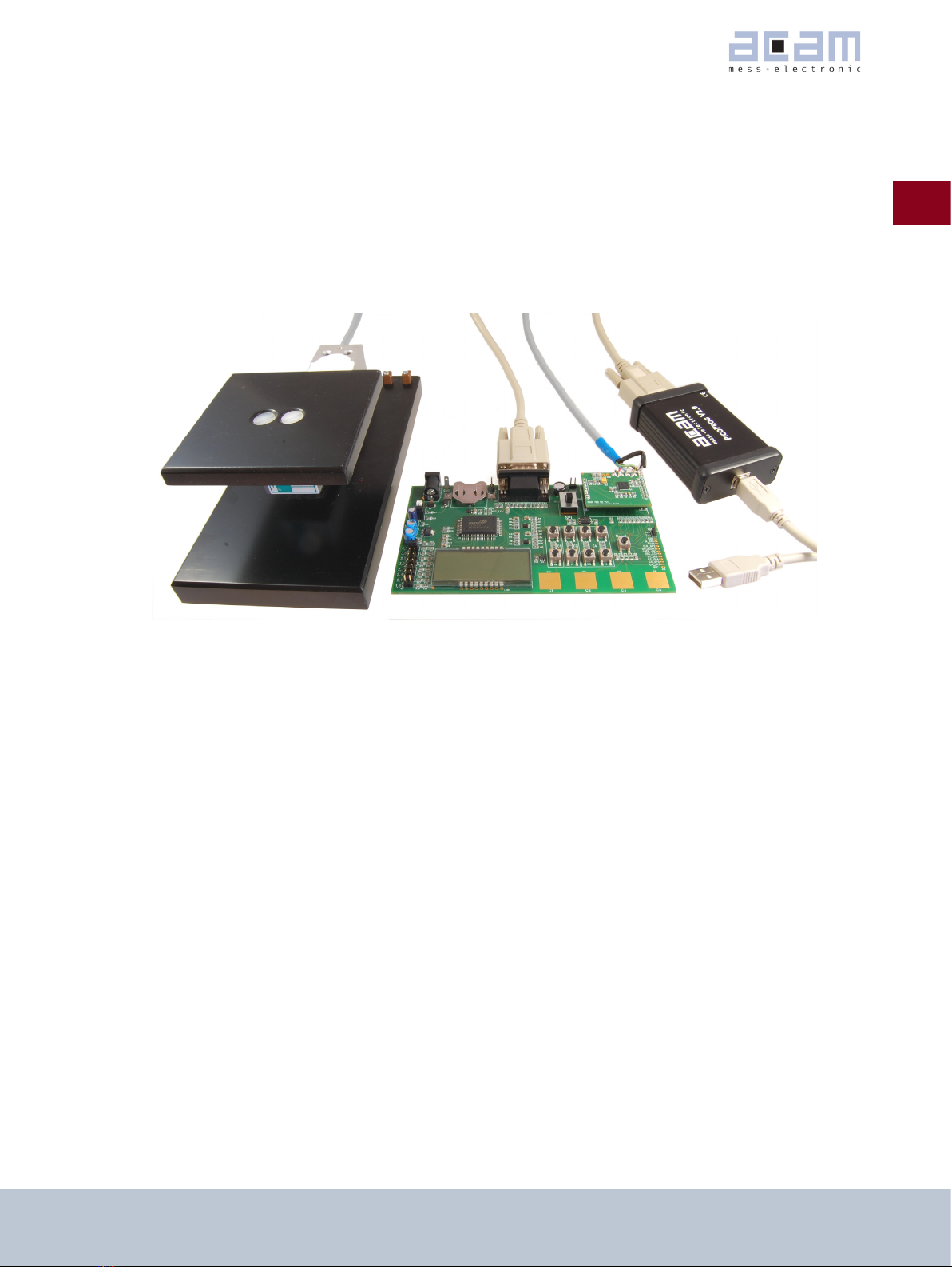
1PSØ9-EVA
2 Connecting Strain Gauges
The evaluation system comes with the load cell already connected to the plug-in module.
In the following we will explain how a user can apply his own load cell. In case of sensors with other than 350 Ohm
resistance the discharge capacitor Cload has to be adapted.
The 2 different plug-in modules are designed to support various applications of PSØ9. For high resolution and solar
applications, for up to 100,000 stable scale divisions, the external bipolar comparator circuit is used. For applica-
tions with lower current consumption and low resolution requirement, the LC variant is used, running with the inter-
nal comparator. The LC module has minimum components and is the ‘low-cost’ variant therefore; however resolution
will be clearly lesser than with the HR module.
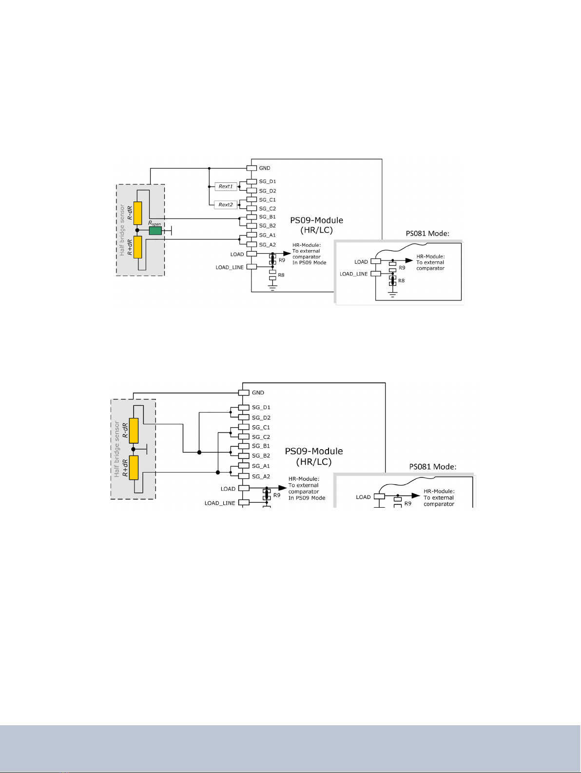
2.1 HR - High Resolution Module
The HR module is targeted for high resolution and solar applications, for up to 100,000 stable scale divisions. The
external bipolar comparator circuit is used in this module.
It is possible to measure up to 4 half bridges. Due to the PICOSTRAIN measurement principle the system does not
need a full bridge. Two resistors, in the following called half bridge, are sufficient.
Figure 2-1: High Resolution Module
2.2 LC – Low Cost module
This is a low-cost version of the High resolution module, with minimum necessary components for operation. The
following are the distinct features that differentiate the LC module from the HR module:
1. No external comparator. This makes the LC module suitable for applications with high, but not the highest
resolution. The internal comparator is used. This reduces the base resolution by 0.8 bit compared to the external
comparator.
2. The 4 MHz ceramic crystal oscillator is not present and there is no possibility to connect an external RC
oscillator to PSØ9. Thus the PSØ9 can be operated only with the built in RC-oscillator. Operating the PSØ9 with the