Accusys ACS-61100 User manual

Preface
1
Preface
Notice
Product features and specifications described in this manual are subject to change without
notice.
The manufacturer shall not be liable for any damage, or for the loss of information resulting
from the performance or use of the information contained herein.
Trademarks
Accusys and the names of Accusys products and logos referenced herein are trademarks
and/or service marks or registered trademarks and/or service marks of Accusys, Inc.
Microsoft, Windows, Windows NT, Windows 2000, Windows 2003, Windows XP, Windows
Vista and MS-DOS are either trademarks or registered trademarks of Microsoft Corporation.
Intel and Pentium are registered trademarks of Intel Corporation. Mac, Mac OS, and
Macintosh are either registered trademarks or trademarks of Apple. Other product and
company names mentioned herein may be trademarks and/or service marks of their
respective owners.
All contents of this manual are copyrighted by Accusys, Inc.
The information contained herein is the exclusive property of Accusys, Inc. and shall not be
copied, transferred, photocopied, translated on paper, film, electronic media, or computer-
readable form, or otherwise reproduced in any way, without the express written permission of
Accusys Inc.
Manual version 1.0
© Copyright 2008 Accusys, Inc.
All rights reserved.

ACS-61100 User’s Manual
About this manual
Congratulations on your selection of the ACS-61100. The card is monitored by a Java-based
RAID GUI.
INTENDED USER
This manual is designed and written for users installing and using RAID GUI. The intended
user should have working knowledge of RAID planning and data storage.
ORGANIZATION OF THE MANUAL
PART ONE: Introduction
Chapter 1: Introduction provides an overview of the card and its features.
PART TWO: Installing the card
Chapter 2: Setting up RAID GUI provides details of how to setting up your card and
connecting to the RAID GUI.
PART THREE: Card Configurations
Chapter 3: Card Connections provides details of the connectors on the RAID card.
PART FOUR: Card BIOS and EFI
Chapter 4: The Card BIOS and EFI allows users to configure a RAID array without
using the RAIDGuard X GUI.
Chapter 5: The optional LCD panel provides another way to configure the card BIOS
and EFI.
PART FIVE: Appendices
Appendix A: Specifications lists the technical details of the ACS-61100 RAID card.
Appendix B: Contact Us lists contact details of Accusys business units around the
world.
Guide to conventions
Important information that users should be aware of is indicated with the following icons:
This icon indicates the existence of a potential hazard that could result in
personal injury, damage to your equipment or loss of data if the safety
instruction is not observed.
This icon indicates useful tips on getting the most from your RAID card.
Important terms, commands and programs are put in Boldface font.
2

Table of Contents
3
Table of Contents
P
REFACE
............................................................................................ 1
Notice................................................................................................................... 1
Trademarks .......................................................................................................... 1
About this manual................................................................................................ 2
INTENDED USER.......................................................................................2
ORGANIZATION OF THE MANUAL.........................................................2
Guide to conventions ........................................................................................... 2
T
ABLE OF
C
ONTENTS
........................................................................ 3
PART ONE - ..................................................5INTRODUCTION
CHAPTER
1
-
........................................................ 6I
NTRODUCTION
Overview.............................................................................................................. 6
Key Features ........................................................................................................ 7
SERIAL ATA (Serial advanced technology attachment).............................. 8
PCI-EXPRESS X 8....................................................................................... 8
FIRMWARE.................................................................................................8
BIOS and EFI .............................................................................................. 8
SGPIO .........................................................................................................8
Before you begin.................................................................................................. 9
WHAT’S IN THE BOX.................................................................................9
OPTIONAL ITEMS....................................................................................10
WHAT ELSE YOU NEED..........................................................................10
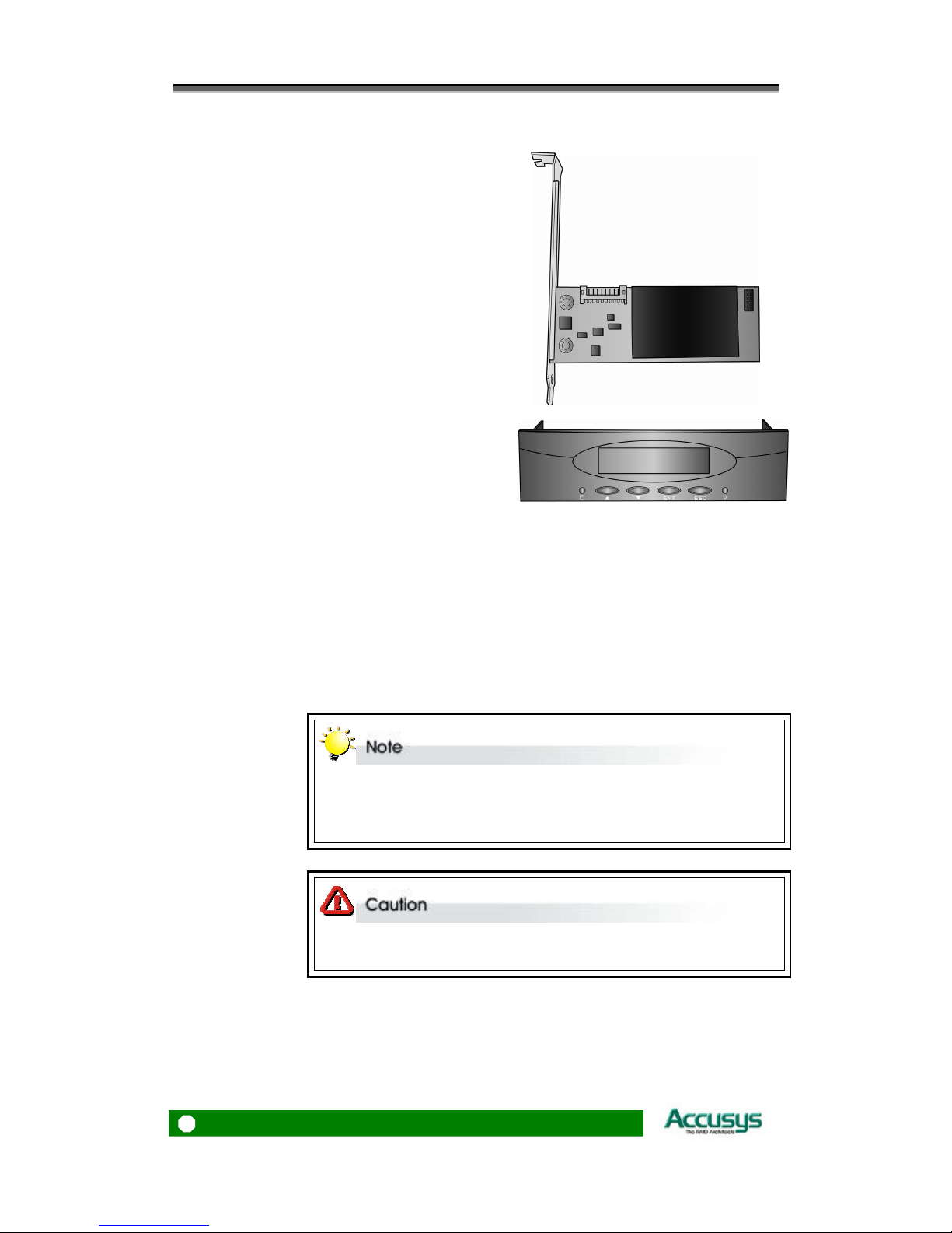
Familiarizing yourself with the RAID card ....................................................... 11
OVERVIEW ...............................................................................................11
PIN SETTINGS.......................................................................................... 12
I2C Connector (2)......................................................................................12
Disk Access LED Connector (4)................................................................12
Disk fault LED Connector (5) ...................................................................13
Serial Port Connector (7)..........................................................................14
Button Port Connector (8).........................................................................14
LCD Panel Connector (9)..........................................................................15
Battery Module Connector (10).................................................................15

ACS-61100 User’s Manual
PART TWO - ...............................16INSTALLING THE CARD
CHAPTER
2
-
....................................................... 17I
NSTALLATION
Installation flowchart ......................................................................................... 17
Pre-installation notices....................................................................................... 18
Card Installation................................................................................................. 19
Hard Drive Connection...................................................................................... 19
LCD Panel (optional) Installation...................................................................... 20
Battery Backup Module (Optional) Installation................................................. 20
PART THREE - ........................21CARD CONFIGURATIONS
CHAPTER
3
-
............................................. 22C
ARD
C
ONNECTIONS
DDRII MEMORY CONNECTOR (1).........................................................23
MINI SAS CONNECTORS (3) ................................................................... 23
DISK ACCESS LED CONNECTOR (4) ....................................................23
DISK FAULT LED CONNECTOR (5) ......................................................23
PCI-EXPRESS X 8 CONNECTOR (6)....................................................... 23
SERIAL PORT CONNECTOR (7) .............................................................23
LCD PANEL CONNECTOR (9) ................................................................ 24
BATTERY MODULE CONNECTOR (10) .................................................24
PART FOUR - .....................................25CARD BIOS AND EFI
CHAPTER
4
-
...................................... 26C
ONFIGURING THE
BIOS
QUICK ARRAY CONFIGURATION ......................................................... 27
BIOS Menu Structure ................................................................................29
CHAPTER
5
-
............................ 33C
ONFIGURING THE
LCD
M
ENU
PART FIVE - .....................................................35APPENDICES
APPENDIX
A
-
.................................................. 36S
PECIFICATIONS
APPENDIX
B
-
........................................................ 37C
ONTACT
U
S
Taiwan - Accusys, Inc. ...................................................................................... 37
America - Accusys U.S.A., Inc.......................................................................... 37
Korea - Accusys Korea, Inc. .............................................................................. 37
China Beijing- Accusys China, Inc.................................................................... 37
Europe - Accusys EU B.V ................................................................................. 37
4

5
Introduction

ACS-61100 User’s Manual
Chapter 1
Introduction
This chapter introduces the features and capabilities of
ACS-61100. You will find:
ÖA full introduction to your RAID card
ÖDetails of key features
ÖA checklist of package contents
ÖA checklist of what else you need to start installation
ÖAn overview of the RAID card
Overview
The ACS 61100 PCI Express to SATA II RAID adaptors provide the latest functionality and
performance for Windows, Linux and MAC operating systems. And with a Java based GUI the
RAIDGuard X server and client software offers improved functionality and manageability.
Using the latest Intel XScale®64-bit RISC processor the eXpeRAID family of adaptors
supports up to 24 x SATA I/II disk drives making it ideal for applications that require high
storage capacity and fast access such as video editing, digital surveillance, file servers and
shared storage.
Using intelligent I/O processing and elaborate algorithms the card bypasses slow disk drives
and rebuilds the data by sustaining a stable throughput and streamlining the data transfer
therefore enabling the smooth handling of heavy loaded and time critical applications.
Data protection is one of the key features of the eXpeRAID adaptors. Not only do they protect
against disk failure but also bad sectors using online recovery and reallocation. Disk
scrubbing is available to fix the bad sectors and online data and parity refresh protects against
data loss caused by media aging.
The RAIDGuard X management software supports the online changing of RAID
configurations; quick configuration on any Java enabled platform; and with the next
generation BIOS and Windows Storport driver its future is guaranteed.
6

Chapter 1 – Introduction
Key Features
ACS-61100 features the following:
zMultiple RAID levels: 0,1, 0+1, 5, 6, and JBOD
zUp to 4 independent disk arrays
zSupport 12~24 x SATA I/II drives
zRAID capacity partitioning: up to 16 slices
zSupport up to 64 LUNs
zVariable stripe sizes, up to 256KB
zSelective initialization method with on-the-fly background initialization and performance
evaluation
zSupport over-2TB volumes
zOnline RAID group expansion
zOnline RAID level migration
zOn-the-fly RAID initialization
zSnapshot for fast backup and restore
zSupport write-back and write-through caching
zSelective and adaptive read/write optimization policies
zFast read response by intelligently bypass slow drive
zAutomatic drive insertion/removal detection and fast disk rebuilding
zOnline bad block data recovery and reallocation
zOnline disk scrubbing with data refresh and parity regeneration
zDisk health monitoring by S.M.A.R.T.
zNVRAM-based transaction log and auto parity resynchronization
zArray roaming and drive traveling with redundant on-disk meta data
zArray recovery to restore RAID configurations
zDual firmware images for firmware recovery
zSupport boot from RAID
zEnclosure components monitoring and control
zOptimized for multiple-stream video processing
zSupport for Windows, Mac OS, and Linux
zJava-based GUI for remote management
zReliable multi-lane SATA connectors
zRoHS compliant
7

ACS-61100 User’s Manual
SERIAL ATA (Serial advanced technology attachment)
The ACS-61100 is designed for use with the latest Serial ATA II hard disk drives. Serial ATA
(often abbreviated as SATA or S-ATA) allows data transfer up to 3 Gbps and is compatible
with older Parallel ATA standards. It has additional advantages over parallel ATA regarding the
cables used: they are thinner, so airflow within computer cases is less impeded, and they can
be up to one meter in length (compared to only 40 cm for parallel ATA).
PCI-EXPRESS X 8
Developed by Intel in 2002, PCI-Express has been developed to match the speed of CPUs. It
provides a serial communications channel of up to 2.5 Gbits/sec in each direction of a pair of
wires. The 8 refers to the number of pairs of wires, so PCI-Express X 8 therefore allows a
maximum of 20 Gbits/sec transfer.
FIRMWARE
Appropriate firmware must be loaded into the card for it to function. The ACS-61100 is
shipped with firmware preloaded. Check the installation disk that came with the package to
find a backup firmware copy. You can also periodically check the vendor’s web site to find the
latest firmware version for use with the card.
BIOS and EFI
The ACS-61100 contains an internal BIOS and EFI which can be used to configure a RAID
Array instead of using the RAIDGuard X GUI. The BIOS and EFI are accessed as the card
boots up and contains all the functionality of the RAIDGuard X GUI. The BIOS and EFI may
be upgraded using the RAIDGuard X GUI. See www.accusys.com.tw for upgrades.
SGPIO
The ACS-61100 uses the SGPIO (Serial General Purpose Input Output) bus to monitor drive
status and control LEDs efficiently. The SGPIO standard is maintained by the SFF Committee.
8

Chapter 1 – Introduction
Before you begin
WHAT’S IN THE BOX
Some vendors may ship certain components as standard, while other vendors treat the same
components as optional. In its most basic configuration, your package should include the
following:
z1 x ACS-61100 PCI-Express to
SATA RAID Card
z6 x Mini Multi-Lane iPass cables
(50cm), including SGPIO connector.
zQuick Start Guide
zInstallation CD (includes Application
Software and Hardware user
manuals)
9

ACS-61100 User’s Manual
OPTIONAL ITEMS
zBattery Backup Module (BBM) – the
BBM stores the cached data in the event
of power supply failure.
zLCD Control panel for card status
checking and advanced configuration.
WHAT ELSE YOU NEED
zLBA 48 bit Hard disk drives (HDDs) (different RAID levels require different
numbers of HDDs. See the RAIDGuard X User Manual to determine how many
HDDs you require).
zDisk enclosure / disk storage locations and power connection for each disk drive.
zHost computer with spare PCI-e slot.
zStatic grounding strap or electrostatic discharge (ESD) safe work area.
The hard drives in a RAID should match in size and speed. All drives in any
array should be identical models with the same firmware versions. Arrays
can use a minimum of 1GB HDDs, however, the smallest drive will determine
the size of the array.
The PCI-e slot on some motherboards is for graphics cards only. Check with
the motherboards vendor for compatibility.
10

Chapter 1 – Introduction
Familiarizing yourself with the RAID card
OVERVIEW
1. DDRII memory connector
2. I2C connector
3. Mini SAS connectors
4. Disk access LED connector
5. Disk fault LED connector
6. PCI-Express x 8 connector
7. Serial port connector
8. Button port connector
9. LCD panel connector
10. Battery module connector
11

ACS-61100 User’s Manual
PIN SETTINGS
The pin settings on the card are as follows:
I2C Connector (2)
Pin 1 SCL
Pin 2 SDA
Pin 3 NC
Pin definition:
Pin 4 GND
Disk Access LED Connector (4)
Pin 1 GND
Pin 2 GND
Pin 3 HD_ACC_LED#0
Pin 4 HD_ACC_LED#1
Pin 5 HD_ACC_LED#2
Pin 6 HD_ACC_LED#3
Pin 7 HD_ACC_LED#4
Pin 8 HD_ACC_LED#5
Pin 9 HD_ACC_LED#6
Pin 10 HD_ACC_LED#7
Pin 11 HD_ACC_LED#8
Pin 12 HD_ACC_LED#9
Pin 13 HD_ACC_LED#10
Pin 14 HD_ACC_LED#11
Pin 15 HD_ACC_LED#12
Pin 16 HD_ACC_LED#13
Pin 17 HD_ACC_LED#14
Pin definition:
Pin 18 HD_ACC_LED#15
12

Chapter 1 – Introduction
Pin 19 HD_ACC_LED#16
Pin 20 HD_ACC_LED#17
Pin 21 HD_ACC_LED#18
Pin 22 HD_ACC_LED#19
Pin 23 HD_ACC_LED#20
Pin 24 HD_ACC_LED#21
Pin 25 HD_ACC_LED#22
Pin 26 HD_ACC_LED#23
Disk fault LED Connector (5)
Pin 1 GND
Pin 2 GND
Pin 3 HD_FAULT_LED#0
Pin 4 HD_FAULT_LED#1
Pin 5 HD_FAULT_LED#2
Pin 6 HD_FAULT_LED#3
Pin 7 HD_FAULT_LED#4
Pin 8 HD_FAULT_LED#5
Pin 9 HD_FAULT_LED#6
Pin 10 HD_FAULT_LED#7
Pin 11 HD_FAULT_LED#8
Pin 12 HD_FAULT_LED#9
Pin 13 HD_FAULT_LED#10
Pin 14 HD_FAULT_LED#11
Pin 15 HD_FAULT_LED#12
Pin 16 HD_FAULT_LED#13
Pin 17 HD_FAULT_LED#14
Pin 18 HD_FAULT_LED#15
Pin 19 HD_FAULT_LED#16
Pin 20 HD_FAULT_LED#17
Pin 21 HD_FAULT_LED#18
Pin 22 HD_FAULT_LED#19
Pin 23 HD_FAULT_LED#20
Pin 24 HD_FAULT_LED#21
Pin 25 HD_FAULT_LED#22
Pin definition:
Pin 26 HD_FAULT_LED#23
13

ACS-61100 User’s Manual
Serial Port Connector (7)
Pin 1 U0_RXD
Pin 2 U1_RXD
Pin 3 U0_TXD
Pin 4 U1_TXD
Pin 5 GND
Pin definition:
Pin 6 GND
Button Port Connector (8)
1
2
9
10
Pin 1 VCC
Pin 2 GND
Pin 3 PAN3
Pin 4 PAN1
Pin 5 PAN4
Pin 6 PAN2
Pin 7 NC
Pin 8 GND
Pin 9 NC
Pin definition:
Pin 10 GND
14

Chapter 1 – Introduction
LCD Panel Connector (9)
Pin 1 GND
Pin 2 VCC
Pin 3 LCD_RS
Pin 4 LCD_VO
Pin 5 LCD_E
Pin 6 LCD_RW
Pin 7 LCD_D1
Pin 8 LCD_D0
Pin 9 LCD_D3
Pin 10 LCD_D2
Pin 11 LCD_D5
Pin 12 LCD_D4
Pin 13 LCD_D7
Pin definition:
Pin 14 LCD_D6
Battery Module Connector (10)
Pin 1 BAT_V
Pin 2 NC
Pin 3 BAT_DETECT#
Pin 4 SDA
Pin 5 SCL
Pin 6 +12V
Pin 7 GND
Pin 8 GND
Pin 9 GND
Pin definition:
Pin 10 +12V
15

ACS-61100 User’s Manual
16
Installing the Card

Chapter 2 – Installation
Chapter 2
Installation
This chapter presents:
ÖInstructions on installing the card in the host system.
ÖInstructions on installing hard drives.
Installation flowchart
Installation of ACS-61100 is simple. This chapter will lead you though the steps:
zInstall the card in a host system.
Install
card
17
zConnect a Mini SAS cable from each hard disk drive in the
intended array to one of the connectors on the card.
zConnect power cables to each of the hard drives.
Connect
hard drives
zHardware installation is complete.
Turn on!
This manual provides full installation and setup instructions for the
ACS-61100 RAID card.

ACS-61100 User’s Manual
Pre-installation notices
Before starting any kind of hardware installation, please ensure that all
power switches have been turned off and all power cords disconnected to
prevent personal injury and damage to the hardware.
To avoid overheating, ACS-61100 should be installed in a well-ventilated
area and in such a way that sufficient airflow is maintained across the card
chips.
Static electricity can damage electronic components. To guard against such
damage:
Work in a static-free environment
Wear a grounded anti-static wrist strap
Store uninstalled components in anti-static bags
Handle PCBs by their edges and avoid touching chips and connectors.
Environmental requirements
Operating Temperature: 5°C to 50°C (41°F to 122°F)
Storage Temperature: -40°C to 70°C (-40°F to 158°F)
Operating Humidity: 5%-85%, non-condensing
Storage Humidity:5%-95%, non-condensing
18

Chapter 2 – Installation
Card Installation
Read the pre-installation notices earlier in this chapter before proceeding.
1. Remove the blanking plate from the
PCI-e slot.
2. Position the connector of the card over
the expansion slot.
3. Press the connector of the card gently
but firmly into the expansion slot until it
is correctly and securely seated.
4. Secure the metal bracket of the card to
the system case with a screw.
5. Go to the Hard drive connection.
Many mother boards only come with one PCI-Express interface. Before
installation ensure there is one free.
Hard Drive Connection
1. Attach Mini SAS cables to the
connectors on the card. One cable can
control a maximum of 4 HDDs.
2. Install the disks in the desired location,
for example within the system case or
within an independent disk rack.
3. Connect the other end of each cable to
the connectors on each of the hard
drives.
4. Attach a power connector to each drive,
either from the host system or from an
independent power source.
19

ACS-61100 User’s Manual
LCD Panel (optional) Installation
Read the pre-installation notices earlier in this chapter before proceeding.
1. Remove or open the system case to
allow access to the 51/4”drive bay you
are going to use for the LCD panel.
2. Remove the blanking plate from this
slot.
3. With the cables connected to the back
of the LCD panel, slide the panel into
the system case.
4. Secure the LCD panel using screws on
either side.
5. Connect the cables to the card.
6. Go to the Card Installation.
Battery Backup Module (Optional) Installation
1. Open the case of the host computer
and remove a blanking plate from the
rear.
2. Connect the cables of the BBM to the
61100 card, as shown.
3. Secure the BBM to the space left by the
blanking plate.
4. Close the case.
The BBM is approximately 2cm high; ensure that your computer case has
sufficient room.
20
Other manuals for ACS-61100
1
Table of contents
Other Accusys PCI Card manuals