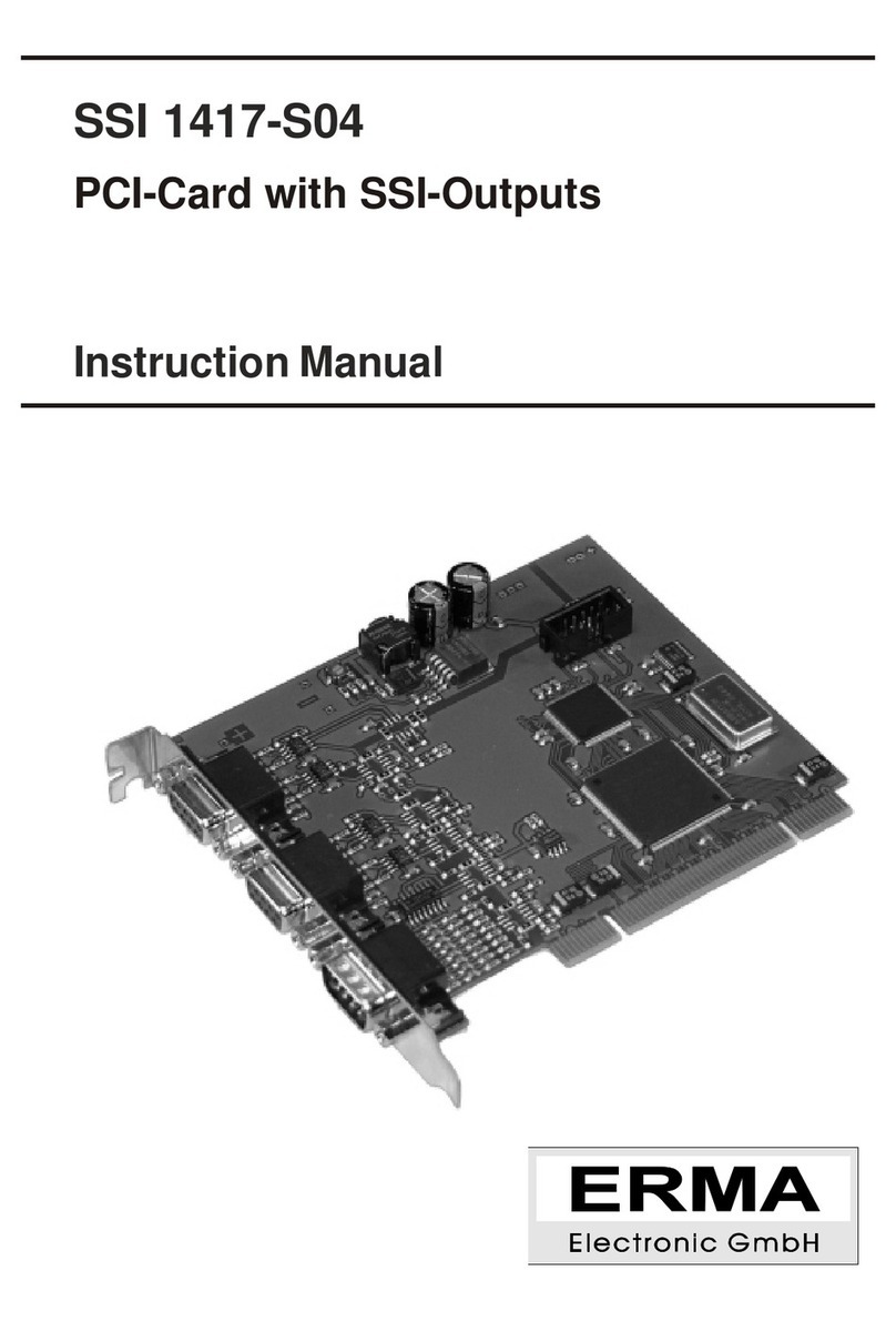
ERMA SSI 1417 User manual

SSI 1417
PCI-Card for SSI-Encoder
Instruction Manual

Warranty
For delivered products our "Allgemeine Lieferungs- und Zahlungsbedingungen" are effective. In no event
ERMA-Electronicoritssuppliersshallbeliableforanyotherdamageswhatsoever(including,withoutlimi-
tation, damages forloss of business profits, business interruption orother pecuniary loss) arising outof or
inability to use this product.
AllproductsfromERMA-Electronicarewarrantedagainstdefectivematerialandworkmanshipforaperiod
oftwo(2)yearsfrom dateofdelivery.IfitisnecessarytoreturntheproducttoERMA, thesenderisrespon-
sibleforshippingcharges,freight,insuranceandproperpackagingtopreventbreakageintransit.ERMA's
warranty does not apply to defects resulting from action of thebuyer, such mishandling, improper interfa-
cing, operation outside of design limits, improper repair or unauthorized modification.
Trademarks
Turbo Pascal, Delphi are registered trademarks of Borland International, INC.
MS-DOS, Windows, Visual Basic are registered trademarks of Microsoft Corporation.
IBM,PCXT/AT,OS/2areregisteredtrademarksinoftheInternationalBusinessMachinesCorporation.
All other trademarks named or portrayed in the text are registered trademarks of its ownwer and are re-
cognized by ERMA-Electronic.

CONTENTS
1. Safety Instructions .......................4
1.1. Symbol Explanation ....................4
2. General .............................5
3. Function.............................5
4. Block diagram .........................6
5. Hints against noisy environment ...............6
6. Installation ...........................7
6.1. Hardware configuration ..................7
6.1.1. Component layout ...................8
6.1.2. Connection of encoders ................9
6.1.3. Connection of inputs..................10
6.2. Open PC..........................10
6.3. Card insertion .......................11
6.4. Close PC..........................11
6.5. Driver installation .....................11
6.5.1. Windows 95 / 98 / ME .................11
6.5.2. Windows NT4.0 ....................11
6.5.3. Windows 2000 .....................12
6.5.4. Windows XP ......................12
6.6. Configure software.....................12
ERMA-Electronic GmbH 2

6.7. Test of the card ......................12
7. Programming ..........................12
7.1. Programming under Windows ...............12
7.2. Programming with ERMA_SSI-DLL ............13
7.2.1. Functions .......................13
7.3. Usage within own applications ..............18
7.3.1. Visual Basic ......................18
7.3.2. Visual C++/ LabWindowsCVI .............18
7.3.3. Delphi .........................19
7.4. Direct programming ....................19
7.4.1. Registers of SSI 1417 .................20
7.4.2. Tips and Tricks.....................22
8. Troubleshooting ........................22
9. Technical datas.........................23
10. Ordering information......................24
11. Notices .............................25
3ERMA-Electronic GmbH
Stand : 03.2010
ssi1417_man_en.vp
Technical subjects to change

1. Safety Instructions
This instrument is produced in accordance with Class II of IEC 348 and VDE
0411.Whendeliveredtheintrumenthasbeentestedtomeetallfunctionsdescri-
bed. Before installing the instrument please read the mounting and servicing in-
structions.Wehavenoliabilityorresponsibilitytocustomeroranyotherpersonor
entity with respect to any liablity, loss or damage caused or alleged to be caused
directlyorindirectlybyequipmentorsoftwaresoldorfurnishedbyus.Readthein-
stallationinstructioncarefully.Noliabilitywillbeassumedforanydamagecaused
by improper installation.
Inspecttheinstrumentmodulecarton for obvious damage.Beshurethereareno
shipping and handling damages on the module before processing. Do not apply
power to the instrument if it has damaged.
The warranty does not apply to defects resulting from action of buyer, such as
mishandling,improperinterfacing,operationoutsideofdesignlimits,improperre-
pair or unauthorized modifications.
1.1. Symbol Explanation
Caution Attention Instruction Tip
Caution: Will be used at dangerous for life and health !
Attention: Will cause damage.
Instruction: If not noticed, Trouble may occur.
Tip: Useful hints for better operation.
ERMA-Electronic GmbH 4
1. Safety Instructions

2. General
The SSI 1417 is a PCI-card for evaluation of 2 SSI-encoders. Additionally there
are2inputstosettheencoderstozeroand2inputsfortriggereddataaquisition.
The card also contains a timer for time driven data aquisition.
Available options:
•Opto-isolation
3. Function
The SSI 1417 will use one PCI-slot within the pc. Because the PCI-bus supports
plugandplay,therearenojumpersorswitchestochangeconfiguration.Thecard
will use 8 x 32-bit-IO-addresses for the function and 16 x 32-bit-IO-adresses for
thePCI-target-controller.YoucanuseanynumberofSSI1417withinonepc(de-
pends on number of PCI-slots). The standard drivers supports up to 4 cards. If
more than 4 cards should be used, you can ask for a driver for more cards. The
cardhasone9-pinSUB-Dmaleconnectorfortheinputsandtwo 9-pinSUB-Dfe-
male connectors for the encoders.
The functions of the card will be handled in a FPGA. This free pro-
gramable device makes it possible to support customer specific
functions without changing the hardware. It is possible to imple-
ment additional special functions or fast controllers within the
FPGA.
5ERMA-Electronic GmbH
2. General

4. Block diagram
5. Hints against noisy environment
All inputs and outputs are protected against noisy environment and high voltage
spikes.Neverthelessthe locationshouldbeselected toensurethatno capacitive
orinductiveinterferencecanhaveaneffectontheinstrumentorconnectionlines.
It is advisable:
•To use shielded, twisted pair cables.
•The wiring of shields and ground (0V) should be star-shaped.
•The distance to interference sources should be as far as possible. If necessa-
ry, protective screen or metal enclosures must be provided.
•Coils of relays must be supplied with filters.
•Parallel wiring of input signals and AC power lines should be avoided.
ERMA-Electronic GmbH 6
4. Block diagram
FPGA
PCI-Target-
Controller
Input-
and
Output-
Logic
SSI-Interface
SSI-Interface
PCI-Bus
2 Triggerinputs+
2 Zeroinputs
Optional
Isolation

6. Installation
The installation of the card should only be done by qualified personal
only.Before installationallcomponentshavetobedisconnectedfrom
powersupply.BecausewithinPC’sandtheperipheralsarehighvolta-
ges it is dangerous to life!
6.1. Hardware configuration
The SSI 1417 uses plug and play and so there is no need for any settings.
7ERMA-Electronic GmbH
6. Installation

6.1.1. Component layout
ERMA-Electronic GmbH 8
6. Installation
male female female
SV1
SV2
SV3
SSI0
SSI1
Trig/Zero
component layout

6.1.2. Connection of encoders
If external encoder supply is used, don’t connect +Vs!
Configured cable for external encoder suppl KA 1417
9ERMA-Electronic GmbH
6. Installation
UBat
+Vs
0V
NSSIDATA
SSIDATA
+Vs
NSSITAKT
SSITAKT
0V
Encoder
Illustration 1Connection with
onboard encoder supply
UBat
+Vs
0V
NSSIDATA
SSIDATA
+Vs
NSSITAKT
SSITAKT
0V
Encoder
Encoder supply
+-
Illustration 2Connection for
external encoder supply
12
UEncoder -
Encoder +
U
SSI 1417
Encoder
UBat
+Vs
0V
NSSIDATA
SSIDATA
+Vs
NSSICLOCK
SSICLOCK
0V
SUB-D 9-pol.
female
User designation
Illustration 3Pinning of
SSI-female-connector

6.1.3. Connection of inputs
TheSSI1417contains2trigger-and2zero-inputs.Theseinputsaredesignedas
EIA RS422, but can also be used as high- or low-side inputs.
ERMA-Electronic GmbH 10
6. Installation
Trigger 1 1
Trigger 2 6
Zero 1 3
Zero 2 8
5
5V +
-
high-side inputs
Trigger 1 2
Trigger 2 7
Zero 1 4
Zero 2 9
5
low-side inputs
0V
NSetZero_2
NSetZero_1
SetZero_2
SetZero_1
NTrig_2
NTrig_1
Trig_2
Trig_1
SUB-D 9-pol.
male
User designation
Illustration 4
Trigger 1 1
2
Trigger 2 6
7
Zero 1 3
4
Zero 2 8
9
differential inputs (RS422)
1
Trigger 1 2
6
Trigger 2 7
3
Zero 1 4
8
Zero 2 9
5V +
-
differential inputs (RS422)

6.2. Open PC
Before opening the pc-case disconnect power supply! The case should be ope-
ned as described by the manufacturer of the PC.
6.3. Card insertion
While nserting the card you could be hurt. This is because all components on the
cardsandinthePChavesharppins.Sothisworkhavetobedonecarefully.Thee
SSI 1417 should be placed in a free PCI-Slot.The card should be installed verti-
cally from above. Afterwards the slot plate of the card have to be screwed to the
backside of the PC-case.
The slot plate is used for mounting and also for shielding. Keep in
mindthat removal of theplate will result in loss ofshieldingandcard
and PC will be more sensitive to EMC. Additionaly the card won’t be
held in slot-position when external force will happen to the connec-
tedcables.Thenthecardcouldmove withintheslotandthatcan re-
sultindamagetotheSSI1417andthePC!So,don’tremovetheslot
plate!
6.4. Close PC
The case should be closed as described by the manufacturer of the PC.
6.5. Driver installation
On most Windows-versions you must have administrator rights to install
drivers.
6.5.1. Windows 95 / 98 / ME
Windows will recognize the new card and ask for the driver. The driver is on the
disc within the directory Driver\Win9x.
ATTENTION: Windows 95 does not support PCI-SubvendorID. So
you can’t use different cards with AMCC S5920Q. If that happens,
please use Windows 98 instead.
11 ERMA-Electronic GmbH
6. Installation

6.5.2. Windows NT4.0
YouhavetostarttheprogramSETUP.EXE.Theprogramisonthedisc withinthe
directory Driver\WINNT40. The program will install the driver and the DLL.
6.5.3. Windows 2000
Windows will recognize the new card and ask for the driver. The driver is on the
disc within the directory Driver\Win2000.
6.5.4. Windows XP
Windows will recognize the new card and ask for the driver. The driver is on the
disc within the directory Driver\WinXP.
6.6. Configure software
All example-programs are shipped as executable and source-code. With the
“Conf”-button you can assign encoder-numbers to each encoder. All example-
programs will only work with encoders 1 and 2.
6.7. Test of the card
After installation the card could be tested.
Therefor you can use the example-programs on the disc.
7. Programming
7.1. Programming under Windows
To build applications for Windows the disc includes different drivers for all Win-
dows-versions.TokeeptheprogrammingoftheSSI1417aseasyaspossible,all
functions of the drivers are handled within one DLL. So all programming of the
card is done by using the DLL.
ThefileERMA_SSI.DLLshouldbecopiedtotheWindowssystemdirectoryorthe
application directory.
ERMA-Electronic GmbH 12
7. Programming

7.2. Programming with ERMA_SSI-DLL
The DLL ERMA_SSI.DLL includes all functions necessary for the work with the
SSI 1417.
The return value of all functions reports an error-code. A return value of
SSI_ERR_OK will show successful execution. Otherwise the code will show the
type of error.
The encoder numbers are bitwise coded. So it is possible to call some special
functionsformorethanoneencoderatatime.Forexampleitispossibletotrigger
allencoderswithonefunctioncall.Allencodersofonecardwillbetriggeredatthe
sametime,encodersondifferentcardswillbetriggerredafteraverysmalltime.
The position values can be up to 44-bit. Therefore all programming languages
shouldhave64-bitintegertypes.Butthatisnotpossiblesoastructureof2x32-bit
integer is used. The structure is devided into a multiturn-part (number of revoluti-
ons) and a signleturn-part (position within one revolution).
Programs written for use with ERMA_SSI-DLL will run under Windows 9x / ME,
WindowsNT 4.0 / 2000 / XP.Thereforonly theDLL and the corresponding driver
is necessary.
7.2.1. Functions
General functions
SSIInit
The function SSIInit must be called once at the beginning of the program. The
function initialises the DLL and the drivers and afterwards all connected encoder
will be searched (AutoConf).
13 ERMA-Electronic GmbH
7. Programming

SSIDeInit
ThefunctionSSIDeInitmustbecalledonceattheendoftheprogram.Allpending
datas will be erased and all interrupts closed.
SSISetLanguage
Thisfunctionsetsthelanguageoftheconfigurationdialogs.Youcanchooseger-
man,englishorautomatic.Automaticmeansthatthedialogswillapearingerman
on german operating systems and english on all other. The following parameters
were used:
•0 = Automatic
•1 = German
•2 = English
SSIConfEncoder
This function opens a dialog for easy configuration of all encoders. The encoder
numbers can be assigned to each encoder, the type of encoder can be set ma-
nually and the encoders can be completely configured. The input parameter
should be 0 for future functions.
SSIAutoConf
This function will try to identify the selected encoders and get all parameters of
them.Theinputparameterisasingleencodernumberorasummed/oredvalueof
multipleencodernumbers.ThefunctionSSIInitusesthisfunctionwithallpossible
encoder numbers to find all encoders.
Example: SSIAutoConf (EncoderNr2)
SSIAutoConf (EncoderNr1 or EncoderNr2 or EncoderNr10)
SSIGetEncoderType
This function is used to get the type ofan encoder. There are the following return
values:
•NO_ENCODER
There is no encoder connected.
•GENERIC_SSI
Connected encoder is a generic SSI-encoder
SSISetEncoderType
Thisfunctionshouldbeusedtomanuallysetthetypeofanencoder.Thepossible
parametersaredescribedinSSIGetEncoderType.Keepinmind,thatallchanges
are lost with the next start of the program.
ERMA-Electronic GmbH 14
7. Programming

SSIGetStatus
This function returns the status of one encoder. The status is bitwise coded. The
following bits are used:
•PRESENT
Ifthisbitisset,anencoderis connectedtotheportcorrespondingtotheenco-
der number.
•STARTED
Thedataaquisitionforthatencoderisstartedwhenset.Datawillonlybesaved
if trigger-modes are set.
•STOPPED
If set, data aquisition for that encoder is stopped.
•SSIVALUES
Ifset,thisbitindicatessaveddatainFIFO.UseSSIGetSSIValuestogettheva-
lues.
•SSIOV
ThisbitindicatesanoverflowintheFIFOforSSI-values.Dataswillbelost.This
happens if the data is read to slowly with the function SSIGetSSIValues (too
fewcallstoSSIGetSSIValuesortoosmallbuffer)orthetriggerspeedistohigh.
The maximum trigger speed depends on the used operating system, running
threads and speed of the PC.
•ZEROED
Not used at the moment.
SSIGetResolution
Thisfunctionreturnstheresolutionofanencoder.Thestructurecontainssepara-
te bitcounts for revolutions (MT) and position (ST).
Expl.: Resolution.MT = 0, Resolution.ST = 17 -> 17-Bit-Singleturn-Encoder
Resolution.MT = 12, Resolution.ST = 13 -> 25-Bit-Multiturn-Encoder
SSISetResolution
Thisfunctionwillsettheresolutionofoneencoder(seedatasheetofencoder).
SSILatch
With this function one or more encoders where triggered. The software trigger
must be set (SSISetTrigger). Get the values with SSIGetSSIValues when trans-
mission is ready.
SSIStop
This function will stop data aquisition of one or more encoders. All encoders con-
nectedtoonecardarestoppedatthesametime,encodersondifferentcardswith
a little delay.
15 ERMA-Electronic GmbH
7. Programming

SSIStart
Thisfunctionwill startdataaquisitionofoneormoreencoders.All encoders con-
nected to one card are started at the same time, encoders on different cards with
a little delay.
SSIGetSSIClock
ThisfunctionreturnsthedivideroftheSSI-clockgenerator.Thefrequencycanbe
calculated as:
Frequency = 5 MHz / Divider
SSISetSSIClock
This function will set th divider for the SSI-clock generator. The divider can be
calculated as:
Divider = Frequency / 5 MHz
Only integer values are possible. Not all values are possible for each encoder.
See the datasheet of the encoders for possible clock rates.
SSIGetTrigger
Thisfunctionreturnsthetriggermodesofanencoder.Themodeisbitwisecoded,
so multiple trigger are possible. Bits are coded as follows:
•TRIGGERSOFT
This is the software trigger. Is this bit set, the encoder can be triggered using
the function SSILatch.
•TRIGGERTIME
Ifthisbitisset,theencoderistriggeredbythecard’stimer.Sotimeddataaqui-
sition is possible.
•TRIGGEREXT1
TRIGGEREXT2
These bits activate triggering with digital inputs Trig1 and/or Trig2. So data
aquisition on external events is possible.
•TRIGGERNULL1
TRIGGERNULL2
These bits activate the zero inputs.
ERMA-Electronic GmbH 16
7. Programming

SSISetTrigger
This function will set the trigger modes for one encoder. Remember, on generic
SSI-encoders the external zero setting is impossible. The bits are coded as seen
at SSIGetTrigger.
SSIGetTimer
Thisfunctionreturnsthedividerofthetimer.Thefrequencycanbecalculatedas:
Frequency = 1 / (Divider * 5 µs)
SSISetTimer
This function will set the divider for the timer of one encoder. The divider can be
calculated as:
Divider = 1 / (Frequency * 5 µs)
Only integer values are possible. Care should be taken that the time between 2
transmissions has to be shorter than the timer frequency or you will loose some
trigger events.
SSIGetMfTime
This function returns the monofloptime of one encoder. Possible values are 2 to
63 µs):
•MFTIME2US = Monofloptime 2 µs
•MFTIME3US = Monofloptime 3 µs
•...
•MFTIME62US = Monofloptime 62 µs
•MFTIME63US = Monofloptime 63 µs
SSISetMfTime
Thisfunctionwillsetthemonofloptimeofoneencoder.OngenericSSI-encoders
the monofloptime will only be set in the SSI 1417. Possible Values are shown in
SSIGetMfTime.
SSIGetSSIValues
With this function saved position values of an encoders could be read out of the
FIFO blockwise. .
17 ERMA-Electronic GmbH
7. Programming

SSIGetConversion
Thisfunctionreturnstheconversionmodeofoneencoder.Possiblevaluesare:
•0 = no conversion
•1 = conversion gray to binary
SSISetConversion
This function will set the conversion mode of one encoder. Possible values are
shown at SSIGetConversion.
SSIGetMasterSlave
This function returns the mode of operation. Possible values are:
•MASTERMODE
•SLAVEMODE
SSISetMasterSlave
Thisfunctionwillsetthemodeofoneencoder.Possiblevaluesareshownabove.
7.3. Usage within own applications
7.3.1. Visual Basic
WithindirectoryInclude\VBonthecdthereisthefileERMA_SSI.BAS.Ifthisfileis
includedwithinaVisualBasic-project,allDLLfunctionsforSSI1417are available
in the project.
7.3.2. Visual C++/ LabWindowsCVI
For C/C++ applications there are an import library ERMA_SSI.LIB and an hea-
der-file ERMA_SSI.H. The library has to be inserted in the linker-options of the
project-settings(seedocumentationofVisualC++/LabWindowsCVI). Includethe
header-file in all source-files where SSI 1417 functions are needed.
An additional method is to use the Windows-function LoadLibrary to connect the
application to the DLL. See documentation of VisualC++ / LabWindowsCVI for
further information.
ERMA-Electronic GmbH 18
7. Programming

7.3.3. Delphi
In the directory Include\Delphi of the cd there is a Delphi unit source file
ERMA_SSI.PAS.Ifthisfileisinserted within a Delphi-project all DLL-functions of
theSSI1417areavailable.Insertthisunittoalluses-declarationswhereSSI1417
functions are needed.
7.4. Direct programming
ForuseoftheSSI1417onotheropertingsystemsortogetfasterreactiontimesor
special reactions other drivers should be implemented. Therefore all needed in-
formation follows.
Addresses and interrupts of the card
The SSI 1417 uses 2 IO-addressranges and 1 interrupt. Because of the plug-
and-play of the PCI-bus these data should be found out. Therefore functions of
the BIOS has to be used like described in “PCI BIOS SPECIFICATION Revision
2.1".
The SSI 1417 uses a configuration space header type 00h. The datas could be
found in the PCI-configuration space on BaseAddress0, BaseAddress1 and In-
terruptLine. With BIOS-function the data could be read out of the configuration
space.BaseAddress0isusedforthe PCI-targetcontroller,BaseAddress1forthe
SSI-functions of the card.
For the BIOS-functions the following informations are necessary:
•VendorID = 0x10E8 (AMCC)
•DeviceID = 0x5920 (S5920Q)
•SubVendorID = 0x1485 (ERMA - Electronic GmbH)
•SubSystemID = 0x0005 (SSI 1417)
Functions of the PCI-target
Initialisation of the PCI-target
Write value 0x87878787 to address BaseAddr0 + 0x60
19 ERMA-Electronic GmbH
7. Programming
Table of contents
Other ERMA PCI Card manuals