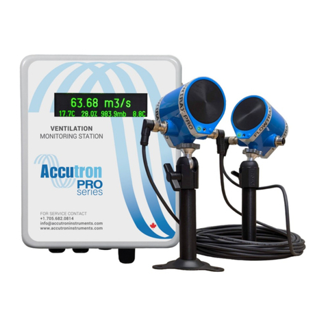
Accutron FlowTrax IS User manual

FlowTrax IS
Technical Operations Manual
Visit www.accutroninstruments.com
Email [email protected]
Phone 1.705.682.0814
V2022.06.21
ACCIS-SYS-002-DR (Drift)
ACCIS-SYS-002-FN (Fan)


i | Page
Important Notice
The ACCUTRON IS line of products is the exclusive copyright property of Accutron Instruments INC.
We reserve the right to make changes to the Accutron products and manuals without further notice to
improve reliability, function or design. Accutron Instruments INC does not assume any liability arising
out of the application or use of any product described herein, nor does it convey any license under its
patent rights, nor the rights of others.
The documentation found within this manual is to provide users of our products with technical
information pertaining to the installation, maintenance and setup of the product.
It is forbidden to use any Accutron documentation for any other purpose which may be detrimental to
the interests of Accutron Instruments INC.
PLEASE NOTE: The newest revision of this manual will be available online at accutroninstruments.com. If
you require any assistance in configuring your new Accutron Pro Device, please call our technicians at
+1-705-628-0814 or email at info@accutroninstruments.com.

ii | Page
Table of Contents
Important Notice ........................................................................................................................................... i
Section 1: General Information..................................................................................................................... 1
1.1 The Manual ......................................................................................................................................... 1
1.1 Safety Guidelines ................................................................................................................................ 2
1.2 Information about your system .......................................................................................................... 2
1.3 Accutron IS Series Specifications ........................................................................................................ 3
Section 2: Installation.................................................................................................................................... 4
2.1 System Explanation............................................................................................................................. 4
2.2 Choosing a Location ............................................................................................................................ 5
2.3 Mounting the Display.......................................................................................................................... 5
2.4 Mounting the Sensors......................................................................................................................... 6
2.5 Connecting the Sensor Cables............................................................................................................. 6
Section 3: Programming................................................................................................................................ 7
3.1 Navigation Buttons ............................................................................................................................. 7
3.2 Programming Datasheet ..................................................................................................................... 8
3.3 Auto Range Feature ............................................................................................................................ 9
3.4 Menu Flow Chart............................................................................................................................... 10
Section 4: Modbus ......................................................................................................................................18
4.1 Modbus Register ............................................................................................................................... 18
4.2 Modbus Connection.......................................................................................................................... 19
Section 5: Troubleshooting......................................................................................................................... 20
5.1 Frequently Asked Questions .............................................................................................................20
5.2 Troubleshooting Flowchart............................................................................................................... 22
Appendix A .................................................................................................................................................. 24
Glossary...................................................................................................................................................24
Equations ................................................................................................................................................25
Accutron IS Drift Replacement Parts List – Mine Drift Airflow Sensor ................................................... 26
Accutron IS Fan Replacement Parts List – Mine Fan Airflow Sensor ...................................................... 27
Accutron IS Drift component checklist ................................................................................................... 28
Accutron IS Fan component checklist..................................................................................................... 28
Appendix B – Diagrams ............................................................................................................................... 29

1 | Page
Section 1: General Information
1.1 The Manual
Refer to this manual for proper installation, operation, setup and maintenance of the Accutron IS
Instrument.
Special attention must be followed to warnings and notices highlighted from the rest of the text to
ensure it will stand out.
Warning: Failure to oblige with the necessary precautions can result in death, serious injury, and/or
considerable damage to the product.
Note: Important information about the product or that part of the manual, helpful hints, and or
troubleshooting advice.
•These instructions do not claim to cover all details or variations in equipment, or to provide for
every possible contingency that may arise during installation, operation, setup and
maintenance.
•For further information or to resolve issues not covered in the manual, consult the Accutron
Technical Service Team.
•The contents of the manual shall not become part of or modify any prior or existing agreement,
commitment or relationship.
•The warranty contained in the contract between parties is the sole warranty of Accutron
Instruments INC.
IMPORTANT: All specifications are subject to change without notice. Ensure your manual is up to date,
the version number can be found on the front page of the manual. If you are unsure please consult the
Accutron Technical Service Team.

2 | Page
1.1 Safety Guidelines
Warning notices must be observed to ensure personal safety as well as that of others, and to protect the
product and the connected equipment.
This device should only be set up and operated in conjunction with this manual. Qualified personnel are
only authorized to install and operate this equipment in accordance with established safety practices
and standards.
Warning: This product can only function properly and safety if it is correctly transported, stored,
installed, setup, operated and maintained.
Note:Always use product in accordance with specifications.
1.2 Information about your system
When you first receive your Accutron IS unit, be sure to record the following.
Table: 1.0 – Accutron Pro System Information
Accutron IS
Part Number (located behind door):
Serial Number (located behind door):
Code Version (located behind door):
Note:If you need to contact Customer Service, this information will be beneficial.

3 | Page
1.3 Accutron IS Series Specifications
Connections: Screw terminal Block Type
Transducers: 3 ½” (Dia.) X 9 1/8” (L)
Display Readout: 16 Characters LCD display.
Each digit is 0.57” (H) X 0.24” (W)
Power Supply: 12.6VDC intrinsically safe power supply
Power Consumption: < 3.3 watts
Input Power: 12.6VDC
Display Units: M/S, CFM, KCFM, M**3/S, FPM
Temperature range: -40°to +60°Celsius
Accuracy: 2% FS or ±0.05 M/S (whichever is greater)
Output type: 4-20mA
Output modes: Normal, Reverse, or Split (used for bi-directional measurements)
Fault/Alarm Output: (Not available)
Sensor cables: 100 feet STD (sensor-to-box). Custom cables up to 500ft.
Connectors: Stainless Steel, with O-ring seals. IP68 rated.
Sensor Mounting: Industrial CATV pan and tilt mount (non-aluminum)
Tunnel sizes: Can accommodate a face-to-face distance of 70 feet.
Programming: User interface onboard using navigation buttons.
Max Airflow: 0 to 40 m/s and higher (essentially no practical upper limit)
Bi-directional
Enclosure Torque
Requirements: 4.5 nm (40 in-lb)
Power Supply port parameters (J1): Ui = 12.5V, Ii = 2.5A, Ci = 0uF, Li = 0uH
Isolated Modbus port parameters (J3): Ui = 5.88V, Ii = 3.25A / 0.5A thermal, Ci =0.3uF, Li = 0uH
Isolated 4-20mA Output port parameters (J2): Ui = 28V, Ii = 93mA / 106mA thermal, Ci = 1uF, Li = 5uH

4 | Page
Section 2: Installation
2.1 System Explanation
The Accutron airflow sensors are compact and reliable instruments, especially designed for measuring
airflows in mining environments. The Accutron IS Drift System is for airflow measurements in mine
drifts whereas the Accutron IS Fan System is for measuring the flow output of large mining fans. Each
system consists of an Indicating Transmitter, cabling and two “ultrasonic sensor” assemblies.
The ultrasonic sensor assemblies are installed in the drift diagonally (one further upstream than the
other) with an “imaginary line” between them intersecting the airflow at a typical angle of 120 degrees.
Ultrasonic pulses are sent back and forth between the transducers across the drift, traveling through the
air current. Let “TA-B” be the time taken for the signal to travel from Transducer Ato Transducer B, and
“TB-A” be the time taken for the pulse to travel from Transducer Bto A. The control unit accurately
measures the time-of-flight for each direction. The difference between the measured times (TA-B – TB-A)
is directly proportional to the airflow. In the case of no moving air, TA-B equals TB-A and there is no time
difference because there is no airflow.
The Accutron IS first internally computes the average velocity of the air in Meters/Sec. In order to
obtain air volumes, the area of the drift is entered into the settings menu (during programming), along
with your selection of measurement units. The system then displays air volumes in the units selected.
Common units used in mining applications are KCFM and M**3/S, other units may also be displayed to
measure the air velocity (Meters/ sec, Feet / Min).
After installation in the drift, measurements are made (area, baseline distance, Face-to-face distance).
Using the navigation buttons, these parameters are entered into the unit.
These parameters are retained in non-volatile Flash memory in the Accutron. Whenever the Accutron
powers up, this information is automatically reloaded.
The system can easily measure air velocities in excess of 1,000,000 cfm with a precision better than any
other conventional methods, as well as low velocity conditions (i.e., 1m/s). In addition, since the system
can sample across the entire drift, readings are more representative than “single point” measurements.
The Accutron considers that there is a “distribution profile” for the air in the drift, making it superior to
other types of measurement methods for fixed installations.

5 | Page
2.2 Choosing a Location
The best location to install the instrument is in a straight section of tunnel that is at least 3 tunnel widths
long. In such a section, the airflow distribution will be well behaved with a maximum airflow in the
center and minimum airflow on the sides (Figure A). We should try to avoid locations where the airflow
is concentrated in one of the corners (Figure B).
Figure BFigure A
The imaginary line between the Accutron sensors works like a “virtual pitot tube” and all flow
measurements occur along this line. In practice, best results are produced when this “imaginary line”
passes through the center of the tunnel, slicing through the airflow distribution profile in a
representative way.
It is also a good idea to carry out and record a 9-point manual airflow survey to verify the airflow
distribution and identify it as a suitable location.
Note: If we need to measure airflow in a less-ideal location. We may need to manually adjust the
calibration correction factor to give accurate flow readings. In this case, the instrument would be
calibrated against a handheld anemometer.
2.3 Mounting the Display
When planning to mount the control unit, you must take into consideration the availability of the power
source, the 4-20mA output signal (i.e., PLC connection), and the sensor cable lengths. In most cases the
control box is mounted on the wall in an electrical room. Extended sensor cable lengths are available for
distances greater than 100 feet.

6 | Page
2.4 Mounting the Sensors
When planning a mounting location for the wall mount sensors, we recommend mounting one sensor
near the top of the drift or duct and the other sensor located near the bottom downstream from the
first on the opposite side, with an “imaginary line” between them intersecting the airflow at a typical
angle of 120 degrees.
Airflow
Airflow
End View Plan View
Illustration of typical mine drift installation
Downstream
Sensor
Upstream
Sensor Upstream
Sensor
Downstream
Sensor
AIRFLOW
Baseline
120 degrees
90° 30°
Face to Face
Once the mounting brackets are installed, thread the sensors onto the mounts and align them at each
other using the pan/tilt adjustment on the bracket.
2.5 Connecting the Sensor Cables
A common mistake made is improperly installing the sensor cables. These must be threaded all the way
to ensure proper functionality.

7 | Page
Section 3: Programming
3.1 Navigation Buttons
NAV BUTTONS
PROG
RUN
RESET
•To program the settings the programming switch must be in the PROG position.
oAs of V.4.03.IS leave the switch in RUN position and just press the center button.
•The LED display will show CONFIG.
•There are 5 buttons. Up, down, left, right, and Select/Enter.
•Use the up and down buttons to select a specific menu or option.
•To change a value, press Select/Enter to enter Edit mode. Up/Down will increment or
decrement your value. Left/Right will let you shift the cursor to the side. The numbers cycle
through 0-9 including a period for decimal values. Press the Select/Enter button again to exit the
edit mode.
•To save and run, keep navigating through the menu until you reach the main menu. There, you
will be able to select either SAVE/RUN or UNDO/RUN. Press the Select/Enter button.
•The display will read SWTCHOFF. Return the programming switch into the RUN position.
Program Switch
Navigation Buttons
Run
Program
Select / Enter
Up
Down
Left
Right
1
45
3
2
3
2
1
4
5
Reset Button
(Bottom left of display board)

8 | Page
3.2 Programming Datasheet
Before programming the Accutron IS, it is a good idea to record the parameters in the following form.
The form should also be filed for future reference.
Menu Option
Default Setting
New Setting Entered
Configuration Menu
(1A)
Flow units
A (M/S)
(1B)
Linear units
A (Meters)
(1C)
Face to face distance
0.0
(1D)
Baseline distance
0.0
(1E)
Cross section area
0.0
(1F)
Air flow direction
A (Normal sign)
(1G)
Zero flow cut-off
0.0
(1H)
Instrument full scale
1000.0
(1I)
4-20mA over range
A (Saturate/Clipping)
(IJ)
Obstruction/fault
timeout in minutes
100 (disabled)
(1k)
4-20mA mode
A (0V 0% 2V 100%)
(1L)
Moving average
15
Advanced Menu
(2A)
Calibration Correction
1.0
*(2B)
Noise filter
0
*(2C)
Wave detection low
threshold
20
*(2D)
Wave detection high
threshold
70
*(2E)
Dynamic range limiting
factor
10
*(2F)
Hysteresis length
10
(2G)
XDUC Gain
D (4)
(2H)
Moving average type
B (First reading)
*(2I)
Alternate updates
B (Enabled)
*(2J)
Envelope Mask
0
Modbus Menu
(3A)
Address
1
(3B)
Baud Rate
B (19200)
(3C)
Parity
A (None)
(3D)
Stop Bits
A (1)
Note: Indicates parameters that should be left at default.

9 | Page
3.3 Auto Range Feature
The Accutron IS comes with a unique feature called auto ranging. It is a quick and easy way to install
your setup without measuring your face-to-face distance. To use this feature, you must do the
following:
1. Make sure that all cables and wires are attached and safely secured.
2. Power the Accutron IS.
3. To start the auto range function, enter a value of 0 in the face-to-face menu. This will force the
Accutron IS to begin auto ranging.
4. Save the settings and restart the system.
5. Upon restart, the display will read “Accutron”, followed by the software version.
6. The display will now read “RANGE0-0” while the transducer sensors receive and send signals
from one another. The display will change depending on the distance.
7. Once the distance has been determined, the display will now be displaying the airflow readings.
Note: The auto range feature works best in non-gusty conditions. To skip auto-range, power on or reset
the unit with the program switch in the PROG position to enter the configuration menu.

10 | Page
3.4 Menu Flow Chart
Config
Advanced
Diagnostics
Modbus
Save/Run
Undo/Run
Reset
Nav Menu
Press
Enter
Running Mode
(Airflow Display)
Settings reset to default
and exit menu
Changes not saved and
exit menu
Save changes and exit
menu
See sheet 2 of 2
See sheet 2 of 2
See sheet 2 of 2
See sheet 2 of 2
Sheet 1 of 2
= Up / Down Button
= Left / Right button
IS Menu Flowchart

11 | Page
1A Enter flow units:
A M/S B kcfm
C cfm D M**3/s
E fpm F usec
1B Linear Units:
A Meters
B Feet
1C Enter face to
face distance:
1D Enter baseline
distance:
1E Enter cross section
area:
1F Enter air flow
direction sense:
A Normal sign
B Reverse sign
1G Enter zero flow
cutoff:
1H Enter instrument
full scale:
1I Enter 4-20mA over
range mode:
A Saturate/Clipping
B Emit 3mA error
1J Obstruction/fault
timeout in minutes
(100 = disabled):
enter value 0-100
1K Enter 4-20mA mode:
A 4mA 0% 20mA 100%
B 4mA 100% 20mA 0%
C Split mode 12mA = 0
1L Enter moving
average (0-255):
enter value 0-255
2A Enter calibration
correction: (0 – 100)
2B Enter noise filter
level: (0 - 100)
2C Enter wave detection
low threshold: (0 - 100)
2D Enter wave detection
high threshold: (0 - 100)
2E Enter dynamic range
limiting factor: (0 - 1000)
2F Enter detection
Hysteresis length:
(0 – 1000)
Config Advanced
2G Enter XDUC Gain:
A 0 B 1 C 2
D 4 E 8 F 16
G 32 H 64
2H Enter moving
average type:
A Start at 0
B First reading
2I Enter alternate
updates:
A Disabled
B Enabled
2J Enter Envelope mask
suppression: (0 – 1000)
2K Enter Master gain:
enter value 0-127
2Q Accutron/J Freq
Tolerance:
0.250
2R Accutron/J Minimum
Sig. Duration (ms):
0.200
2S Accutron/J Sampling
Period (ms):
300.000
4A Select diagnostic
output:
A Envelope detect
B Filter
4B Test current output:
enter value between
4-20
Diagnostics
2N Accutron/J Signal
Filter:
A – Disabled
B – Enabled
2O Accutron/J Diag
Mode:
A – Bounding Box
B – Crossing Indexes
2P Accutron/J Min
Amplitude:
175.000
Modbus
3A Enter Modbus
address:
enter value 1-247
3B Select Modbus
baud rate:
A 9600 B 38400
C 57600 D 115200
3C Select Modbus
parity:
A None B Odd
C Even
3D Select Modbus
Stop Bits:
A 1 stop bits
B 2 stop bits
3E Select Modbus
TX delay:
A 0ms B 50ms
C 100ms
Note: Clicking the left button will back out
of Config, Advanced, Modbus and Diag
Menus.
*New as of V.4.03.IS
Sheet 2 of 2
IS Menu Flowchart

12 | Page
Enter Tag Number : Enter the Tag Number desired. This option is
mostly used if you want to identify which unit
you are working with. It is simply text
information.
[1A] Enter flow units :
A M/S B kcfm
C cfm D M**3/s
E fpm F usec
Press the letter that corresponds with the
desired unit. M/S (meters per second) is the
default.
[1B] Linear Units :
A Meters
B Feet
Choose the desired unit of measurement
“Meters” is selected by default. If “Feet” is
selected, then every option will be calculated
in feet.
[1C] Enter face to
face distance :
0.0
Feet
This is the distance between the faces of the
two sensors. By default, the distance is 0.0.
This causes the instrument to enter the “auto
range” mode when it is first powered on. This
value can also be physically measured and
entered manually.
[1D] Enter baseline
distance :
0.0
Feet
This is the horizontal distance between the
two sensors. By default, this value is the same
as the face-to-face. This value is physically
measured and will always be less than the
face to face distance.
[1E] Enter cross section
area :
0.0
Cubic Feet
Enter the cross sectional area of the section
between the two sensors.
[1F] Enter airflow
direction sense:
A Normal sign
B Reverse sign
Selecting the Reverse sign multiplies the
value on the display by –1. Use this option if
you would like to receive positive values
instead of negative values.

13 | Page
[1F] Enter airflow
direction sense:
A Normal sign
B Reverse sign
Selecting the Reverse sign multiplies the
value on the display by –1. Use this option if
you would like to receive positive values
instead of negative values.
[1G] Enter zero flow
cutoff :
0.0
kcfm
Zero flow cut off allows you to select a
specific range of measurements. For example
if you are working in kcfm and enter a value
of 100, and your full scale setting is 500, your
measurement range will now be 100-500
kcfm as opposed to 0-500 kcfm.
[1H] Enter instrument
full scale :
1000
kcfm
This is the full-scale reading of the instrument
in the units selected. Flow readings greater
than this will result in a “*” to appear in the
right most display indicating that you have
exceeded your full scale range.
[1I] Enter 4-20mA over
range mode:
A Saturate / Clipping
B Emit 3mA error
Selecting A,if the flow exceeds full-scale, the
mA output will saturate at 20mA. Selecting
B,if the flow exceeds full-scale, the
instrument will output 3mA indicating that
the full scale or max airflow has been
exceeded.
[1J] Obstruction/fault
timeout in minutes
(100 = disabled):
100
Obstruction/fault allows the instrument to
output the last known good reading in the
event there is something blocking the signal
between the two sensors for example a large
vehicle. The value can be selected from 0-99
minutes. Once the time has elapsed the unit
will output a 0.3V error.
[1K] Enter 4-20mA mode :
A 4mA 0% 20mA 100%
B 4mA 100% 20mA 0%
C Split mode 12mA 0%
A (Normal mode) 4mA corresponds to
minimum airflow. (20mA max)
B (Reverse mode) 4mA corresponds to
maximum airflow. (20mA min)
C (Split mode) 12mA corresponds to 0
airflow, 4mA to max negative, and 20mA to
max.

14 | Page
[1L] Enter moving
average (0 - 255) :
0
In most cases the measured airflow is slightly
turbulent, by averaging the readings, the
analog output will behave in a smoother rate
of change allowing for a better representation
of airflow in the measured area.
Advanced Menu
[2A] Enter calibration
correction:
1.0
The calibration correction allows for a
correction factor to be entered in the case of
difficult applications. It is calculated by
dividing the expected reading / actual reading.
[2B] Enter noise filter
level:
0
value (0-100)
The noise filter is a provision for dealing with
extreme noise. Normally it is set to 0.
[2C] Enter wave detection low
threshold:
20
value (0-100)
This option is used to specify the lower wave
detection threshold in order to properly detect
the ultrasonic signal. In almost all cases this
value should be left at 20.
[2D] Enter wave detection high
threshold:
70
value (0-100)
This option is used to specify the upper wave
detection threshold in order to properly detect
the ultrasonic signal. In most cases this value
should be left at 70.
[2E] Enter dynamic range limiting
factor:
10
value (0-1000)
Places a limit on how much weak signal noise
may be expanded (digitally amplified). It
prevents over amplification of noise in the
absence of a valid signal.
[2F] Enter detection hysteresis
length:
10
value (0-1000)
This option determines the minimum
acceptable length of the waveform. Default is
50 units.

15 | Page
[2G] Enter XDUC Gain:
A 0 B 1 C 2
D 4 E 8 F 16
G 32 H 64
This option sets the Transducer signal gain. In
cases where the two sensors are separated by
a long distance the gain should be set higher.
The default gain is 4 = 0-20ft separation, 8 =
20-30ft, 16 = 30-40ft, 32 = 40-50ft and 64 =
50-60ft.
[2H] Enter moving average type:
A – Start at 0
B – First Reading
Upon powering up this will select whether to
start the averaging at 0, (the airflow reading
will slowly ramp up to the actual reading) or
using the first reading registered by the
instrument
[2I] Enter alternate updates:
A – Disabled
B – Enabled
Consult an Accutron Representative before
changing. Default is Enabled.
[2J] Enter Envelope mask
suppression:
0
(0 – 1000)
Consult an Accutron Representative
[2N] Accutron/J Signal
Filter:
A – Disabled
B – Enabled
This option enables or disables different
signal processing. This can be used in noisy
environments.
[2O] Accutron/J Diag
Mode:
A – Bounding Box
B – Crossing Indexes
Diagnostics PC display option.
[2P] Accutron/J Min
Amplitude:
128.000 Filter amplitude adjustment (128 to 400)
[2Q] Accutron/J Freq
Tolerance:
0.250 Frequency tolerance adjustment.

16 | Page
[2R] Accutron/J Minimum
Sig. Duration (ms):
0.600 Minimum valid signal duration.
[2S] Accutron/J Sampling
Period (ms):
300.000 Signal sampling period.
Modbus Menu
[3A] Enter Modbus address:
Enter value 1-247 Enter a Modbus Slave address for this device.
[3B] Select Modbus port
baud rate:
A - 9600 B - 19200
C - 57600 D - 115200
Select the baud rate for RS485 output.
[3C] Select Modbus
parity:
A None B Odd
C Even
Set the Modbus parity for this device.
[3D] Select Modbus
Stop Bits:
A 1 stop bits
B 2 stop bits
Set the Modbus Stop bits for this device.
[3E] Select Modbus
TX delay:
A 0ms B 50ms
C 100ms
Delays the response time of this device to
Modbus request.
Table of contents
Other Accutron Measuring Instrument manuals