Ace AT Series Manual

Page | 0
Model AT Series Rotary
Accumulation Table
Installation and Maintenance Manual
REV 4-11-2019 Automated Cells & Equipment, Inc.
9699 Enterprise Drive
Painted Post, NY 14870
P: 607.936.1341 F: 607.936.1531

Section 1 - Introduction
Page | 0
Table of Contents
Section 1 - Introduction ................................................................................................................................1
Section 2 - How to Use This Manual.............................................................................................................1
Section 3 –Specifications..............................................................................................................................1
AT24 ..........................................................................................................................................................2
AT36 ..........................................................................................................................................................2
AT48 ..........................................................................................................................................................3
AT60 ..........................................................................................................................................................3
AT72 ..........................................................................................................................................................4
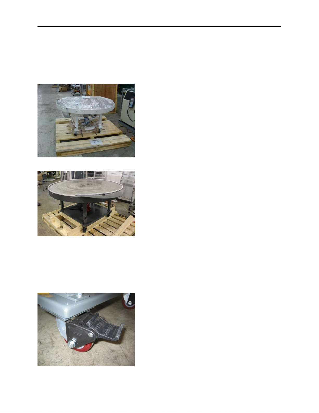
Section 4 –Unpack/Uncrate .........................................................................................................................5
Section 5 –Setup ..........................................................................................................................................5
Floor Locks ................................................................................................................................................5
Height Adjustment....................................................................................................................................6
Applying Power.........................................................................................................................................7
Section 6 –Operation ...................................................................................................................................7
Power On and Speed Adjustment.............................................................................................................7
Part Diverter Adjustment..........................................................................................................................8
Drip Tray conversion kit............................................................................................................................8
Section 7- Safety ...........................................................................................................................................8
Section 8 –Maintenance ..............................................................................................................................8
Cleaning the Unit ......................................................................................................................................8
Lubrication AT24, AT36.............................................................................................................................9
Lubrication AT48, AT60, AT72...................................................................................................................9
Manual Lift..............................................................................................................................................10
Turntable Top Removal...........................................................................................................................10
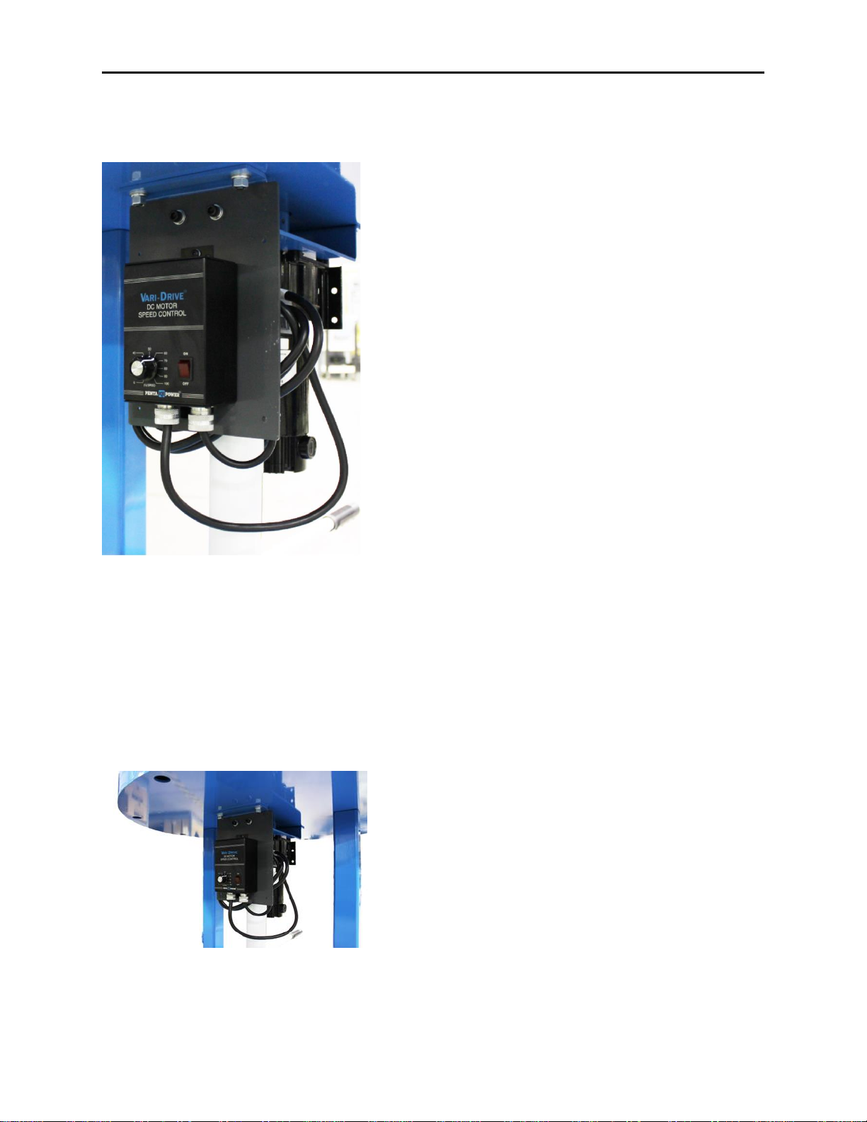
Variable Speed Controller (KBWM-120).................................................................................................11
MODEL NO. & VOLTAGE RATING........................................................................................................11
ELECTRICAL RATINGS ..........................................................................................................................12
PLUG-IN HORSEPOWER RESISTOR® CHART ........................................................................................12
AMATURE FUSE SELECTION CHART ....................................................................................................12
CONTROL LAYOUT...............................................................................................................................13

Section 1 - Introduction
Page | 1
AC LINE & ARMATURE CONNECTION..................................................................................................13
ACCEL TRIMPOT ADJUSTMENT ...........................................................................................................14
DECEL TRIMPOT ADJUSTMENT ...........................................................................................................14
Troubleshooting......................................................................................................................................15
Section 9 –Contact Information.................................................................................................................15

Section 1 - Introduction
Page | 1
Section 1 - Introduction
Congratulations on your purchase of the Model AT Rotary Accumulation Table. The Model AT Rotary
Accumulation Tables are designed to accumulate work-in-process or finished parts. The standard
turntable features variable speed rotation and a mild steel, stainless or UHMW plastic top. The
following information describes the proper operation and maintenance of the AT rotary accumulation
tables.
Section 2 - How to Use This Manual
This manual was created to assist qualitied application, programming and maintenance personnel in the
proper installation and maintenance of the Model AT Rotary Accumulation Tables. Guards are
sometimes shown removed to clarify components and procedures for maintaining the equipment. DO
NOT operate equipment without all guards in place. IMPORTANT: Please review this manual in its
entirety prior to setting up, installing and commissioning the Model AT Rotary Accumulation Tables.
CAUTION: As with any piece of automation equipment, always perform a risk assessment for the
specific application to determine the proper level of guarding and safeguards to protect all personnel
from injury.
Section 3 –Specifications
The Model AT Rotary Accumulation Table comes in five different sizes. Specifications for each size are
shown below. Model AT Rotary Accumulation Tables are available with three different top
configurations, MS- Mild Steel, SS- Stainless Steel, and MSU- UHMW plastic over a mild steel powder
coated top.

Section 3 –Specifications
Page | 2
AT24
Table top
24” Diameter x 11 Ga. reinforced top. Plain steel
top surface (no finish), powder coat on underside.
Adjustable part diverter included
Turntable support
Low-friction turntable support bearings
Drivetrain
Medium duty DC variable speed drive, 1-8 RPM
complete with 9 foot 120 VAC power cord
Capacity
75 lb. part handling capacity
Frame Construction
Mild steel 2 post design with powder coat finish
and brake casters for portability
Tabletop Height
Adjustable via hand operated hydraulic jack for
16” of vertical height adjustment 29” to 45” top of
table
AT36
Table top
36” Diameter x 11 Ga. reinforced top. Plain steel
top surface (no finish), powder coat on underside.
Adjustable part diverter included
Turntable support
Low-friction turntable support bearings
Drivetrain
Medium duty DC variable speed drive, 1-8 RPM
complete with 9 foot 120 VAC power cord
Capacity
75 lb. part handling capacity
Frame Construction
Mild steel 2 post design with powder coat finish
and brake casters for portability
Tabletop Height
Adjustable via hand operated hydraulic jack for
16” of vertical height adjustment 29” to 45” top of
table

Section 3 –Specifications
Page | 3
AT48
Table top
48” Diameter x 7 Ga. reinforced top. Plain steel top
surface (no finish), powder coat on underside.
Adjustable part diverter included
Turntable support
Low-friction turntable support bearings
Drivetrain
Medium duty DC variable speed drive, 1-6 RPM
complete with 9 foot 120 VAC power cord
Capacity
150 lb. part handling capacity
Frame Construction
Mild steel 4 post design with powder coat finish
and brake casters for portability
Tabletop Height
Adjustable via hand operated hydraulic jack for
10” of vertical height adjustment 29” to 39” top of
table
AT60
Table top
60” Diameter x 7 Ga. reinforced top. Plain steel top
surface (no finish), powder coat on underside.
Adjustable part diverter included
Turntable support
Low-friction turntable support bearings
Drivetrain
Heavy duty DC variable speed drive, 1-6 RPM
complete with 9 foot 120 VAC power cord
Capacity
200 lb. part handling capacity
Frame Construction
Mild steel 4 post design with powder coat finish
and brake casters for portability
Tabletop Height
Adjustable via hand operated hydraulic jack for
10” of vertical height adjustment 30” to 40” top of
table

Section 3 –Specifications
Page | 4
AT72
Table top
72” Diameter x 7 Ga. reinforced top. Plain steel top
surface (no finish), powder coat on underside.
Adjustable part diverter included
Turntable support
Low-friction turntable support bearings
Drivetrain
Heavy duty DC variable speed drive, 0.5-3 RPM
complete with 9 foot 120 VAC power cord
Capacity
500 lb. part handling capacity
Frame Construction
Mild steel 4 post design with powder coat finish
and brake casters for portability
Tabletop Height
Adjustable via hand operated hydraulic jack for
10” of vertical height adjustment 33” to 43” top of
table

Section 4 –Unpack/Uncrate
Page | 5
Section 4 –Unpack/Uncrate
After receiving your ACE Model AT Rotary Accumulation Table, carefully unpack the unit and check for
any damage. If unit is damaged, please contact the freight company. ACE can assist you with any
replacement parts you may require.
Your Model AT Rotary Accumulation Table will
arrive lagged and or strapped to a pallet and
stretch wrapped to protect the exterior finish. You
may remove the stretch wrap and the lag screws
or straps from the rotary table.
Next, remove your new Model AT Rotary
Accumulation Table from the pallet and cover case
and place it in its final location.
NOTE: Do not attempt to lift the entire unit with
the eye or damage may result.
The unit may be lifted with a fork truck from under
the base plate. Lift slowly and stabilize the table
during the process.
Section 5 –Setup
Floor Locks
Roll the Model AT Rotary Accumulation Table into
position on the factory floor and lock all four
swivel casters prior to use. To lock the swivel
caster, simply depress the foot pedal down until it
clicks. To release, push on the top of the pedal
until the pedal.

Section 5 –Setup
Page | 6
Height Adjustment
To adjust the working height of the Model AT upward:
1) Loosen the height adjustment locks.
2) Make sure the lift lowering valve is tight (rotate
clockwise to tighten). The manual lift handle is used
for tightening and loosening the lift lowering valve.
3) Place the handle with the notched end over the T-
shaped valve to loosen or tighten.
4) Place lift handle into receiver on lift and pump
handle up and down until the desired height is
reached.
5) Tighten all four height adjustment locks.
6) To lower the table, rotate the T-shaped lowering
valve counterclockwise with the lift handle.
CAUTION: Rotate the lowering valve slowly to provide a
smooth motion. If the table is lowered too rapidly, damage
may result.
After adjusting the table height, lock all telescoping legs in
position by rotating the levers clockwise until tight. To
loosen the height adjustment lock, rotate counter clockwise.
All height lock levers have a ratchet feature. To use the
ratchet feature, pull out on the lever and reposition the
handle where desired.

Section 6 –Operation
Page | 7
Applying Power
Uncoil the provided 9ft cord and plug into a
grounded 15 Amp outlet.
NOTE: Make sure the On/Off toggle switch on the
controller is in the off position prior to applying
power.
Section 6 –Operation
Power On and Speed Adjustment
To power up the Model AT Rotary Accumulation
Table place the POWER switch in the ON position.
The turntable speed may be adjusted by rotating
the SPEED CONTROL KNOB. Rotate clockwise to
increase speed and counterclockwise to reduce
speed.

Section 7- Safety
Page | 8
Part Diverter Adjustment
The part diverter rail moves accumulated parts to
the center of the rotary table, allowing room for
new parts to enter the table. The amount of
offset can be adjusted by loosening the hand knob
securing the diverter arm and sliding the diverter
to the desired position.
Drip Tray conversion kit
The optional Drip Tray Conversion Kit may be
used to collect run-off fluid from damp or wet
parts. The fluid will drain off the table top into
the turn table pan and collect. A central ½ NPTF
drain connection is provided for attachment of
customer supplied hose.
Section 7- Safety
The Model AT Rotary Accumulation Tables should have all four swivel casters locked prior to use. Be
sure to have all loose clothing and hair tied back before and during operation of the Model AT rotary
accumulation table.
Section 8 –Maintenance
Cleaning the Unit
For long life and proper operation, the Model AT Rotary Accumulation Table should be kept clean and
free of debris. The unit can be vacuumed off or wiped down with a multipurpose cleaner such as
Fantastic®. The table has holes under each com roller to allow debris to exit the bottom of the table.
NOTE: These holes are plugged with the Drip Tray Conversion Kit option.

Section 8 –Maintenance
Page | 9
Lubrication AT24, AT36
The gearbox utilized on the model AT24 and AT36 is lubricated-
for-life and does not require servicing of the lubricant.
Lubrication AT48, AT60, AT72
For optimum performance on the Model AT48,
AT60, AT72, the gearbox oil level should be
checked every month or 500 hours of operation.
To check the oil level, remove one of the upper oil
level plugs to verify the gearbox has a sufficient
level of oil. The oil should be drained and refilled
every six (6) months or 2500 hours with Mobil
600W Super Cylinder oil.
NOTE: Make sure to check the oil level on both
the primary and secondary gearboxes.

Section 8 –Maintenance
Page | 10
Manual Lift
The manual lift should not require servicing.
However, if the lift is not raising the turntable,
verify the lowering valve is tight. If it is still not
raising the turntable, verify there is oil in unit. If
low on oil, add good grade hydraulic jack oil. The
roller bearing support rollers are permanently
lubricated and do not require maintenance
however, zerk fittings are installed and accessible
from the outside of the rotary table. Apply one to
two pumps of moly grease to each unit as needed
for higher duty cycle environments.
Turntable Top Removal
On occasion, the turntable top may require
removal to properly clean the turntable support
pan. The top can be removed by backing out the
setscrew contained in the hub connecting the unit
to the shaft on the gearbox.
NOTE: The hub is located above the gearbox
mounting bracket and under the turntable pan.
The hub will be powder coated when a mild steel
top is provided and stainless steel when a
stainless steel top is provided.
A 3/8-16 tap is provided in the center of the
turntable top, allowing a lifting eye to be threaded
into the top for easy removal with a hoist. A set
screw is provided to keep the threads free and
clear of debris. Remove the set screw prior to
installing the lifting eye.

Section 8 –Maintenance
Page | 11
Use only a load-rated lifting eye rated at a
minimum of 1,000 lbs. for removal of the top.
WARNING: Lifting eye and hoist should be used
to remove the table top only. Do not attempt to
lift the entire unit with the eye or damage may
result.
Variable Speed Controller (KBWM-120)
The following controller specifications are provided for reference. For further information, please refer
to the attached controller documentation.
MODEL NO. & VOLTAGE RATING
Model Number
AC Line Voltage
VAC 50/60 Hz
Armature
Voltage (VDC)
KBWM –120
115
0 - 90

Section 8 –Maintenance
Page | 12
ELECTRICAL RATINGS
Model Number
Part No.
Input Voltage
(VAC -50/60Hz)
Max. AC
Load Current
(RMS Amps)
Armature
Voltage (VDC)
Max. DC
Load Current
(DC Amps)
Max.
Horsepower
HP, (kW)
KBWM –120
9380
115
5.0
0 - 90
3.5
1/3,(0.25)
PLUG-IN HORSEPOWER RESISTOR® CHART
90 VDC
Max Horsepower
Range
Approx.
Motor Current
(DC Amps)
Plug-in Horsepower
Resistor® Value
(OHMS)
Individual
Plug-in Horsepower®
Resistor Part No.
1/8
1.3
0.1
9838
1/4
2.5
0.05
9839
AMATURE FUSE SELECTION CHART
90 VDC
Max Horsepower
Range
Approx.
Motor Current
(DC Amps)
Fuse
Rating
(AC Amps)
1/8
1.3
2
1/4
2.5
4

Section 8 –Maintenance
Page | 13
CONTROL LAYOUT
AC LINE & ARMATURE CONNECTION

Section 8 –Maintenance
Page | 14
ACCEL TRIMPOT ADJUSTMENT
DECEL TRIMPOT ADJUSTMENT

Page | 15
Troubleshooting
Symptoms
Corrective Action
Turntable fails to Rotate
Plug power cord into an available 120VAC
outlet.
Turn power switch to ON position.
Rotate speed control knob clockwise to
increase speed.
Verify the 120VAC outlet is operating
property.
Check/ replace controller fuse.
Lift Fails to Raise
Verify height adjustment locks loosened.
Verify lift lowering valve is tight.
Verify lift has oil in it.
Turntable Drive is Turning
but top is Stationary
Verify setscrew in table top hub is tightly
secured.
Verify setscrew has not sheared. Replace
setscrew if required.
Verify setscrew is lined up with shaft keyway.
Section 9 –Contact Information
Michael Lucey
Business Unit Manager
Phone: (607) 936-1341
Email: [email protected]
Al Herzog
Service Manager
Phone: (607) 936-1341
Email: [email protected]
Jim Morris
President
Phone: (607) 936-1341

Section 10 Recommended Spare Parts list
Page | 16
If you experience a problem and need to reach a service technician:
During office hours: Monday thru Friday, 7:30am-5:00pm EST. 607-936-1341
In order to provide you with the most efficient assistance, please be prepared to provide the
information in the table below to the answering service personnel. The ACE identification information is
available from a nameplate located on the MT Series Drawer Cabinet
Telephone number + name for call back assistance
ACE Project #
(look at serial tag on machine)
Is this a down production situation?
What task does this equipment do?
Is this a mechanical or electrical problem?
Section 10 Recommended Spare Parts list
The following section provides a list of the recommended spare parts for the Model AT Series Rotary
Accumulation Table. Upon request, Automated Cells & Equipment would be happy to provide you a
quote on spare parts for your Model AT Series Rotary Accumulation Table.

Section 10 Recommended Spare Parts list
Page | 17
Common Spare Parts (All Models)
Recommended
spare Qty.
Item
Description
E4.04169.929.BRK2
Caster - 4" Swivel, Poly HiTech Wheel, Techlock Brake
CF-1 1/4-B
Cam Follower - 1 1/4" Diameter with 1/2-20 Male Stud
3/16 Lube Fitting, 3930 Lbs. Dynamic Rating Capacity
1728-B
Grease Fitting, #20100, 3/16"
2454K71
Hand Knob - Comfort Grip, 1/4-20 x 1" Stud
3014T471
Eye Bolt - Steel, with Shoulder, 3/8-16 Thread
1300 lb. Working Load, 1 1/4" Thread Length
6271K31
Adjustable Handle - Die Cast, 3/8-16 x 3/4" Stud
91259A574
Shoulder Screw - 5/16" Shoulder Dia, 1/4" L Shoulder,
1/4"-20 Thread, Alloy Steel
VG-P18CC-20
Guide Rail - 11/12Ga x 3/4" J Leg, 3/4" Face, 20Ft
Table of contents
Other Ace Indoor Furnishing manuals
Popular Indoor Furnishing manuals by other brands

J.Burrows
J.Burrows JB5TMTLSWE Assembly instructions

Wyndham Collection
Wyndham Collection WC-R4100-60-DBL Installation

Seconique
Seconique Wexford Assembly instructions

Mocka
Mocka Maisie Scalloped Desk Assembly instructions

IKEA
IKEA BILLY BYOM GLASS DOOR FOR HEIGHT EXT instructions

fantastic furniture
fantastic furniture Oslo Table manual