Ace 73-250 Mounting instructions

ACE INDUSTRIAL PRODUCTS
PORTABLE FUME EXTRACTOR
MODEL 73-250
SAFETY & INSTRUCTION MANUAL
CAUTION: This device is powered by rotating electrical machinery!! Careless or improper use may result in
personal injury. Read the Safety Precautions and Warnings contained within prior to operating this machine.
READ AND SAVE THESE INSTRUCTIONS.
SAFETY WARNINGS & CAUTIONS
FAILURE TO OBSERVE THE FOLLOWING
PRECAUTIONS COULD RESULT IN SERIOUS
INJURY, INCLUDING DEATH IN EXTREME CASES.
SAVE THESE INSTRUCTIONS.
WARNING: (EXPLOSION HAZARD)
This unit contains universal motors which spark during
normal operation. Do not use in areas contaminated
by volatile or flammable materials as these sparks may
ignite the contaminates and cause a dangerous
explosion.
WARNING: (VOC’s & Airborne Microbes)
The filters used in this unit will remove solid particulate
ONLY and will not eliminate Volatile Organic
Compounds (VOC’s) or airborne microbes (bacteria,
mold & viruses) that may be a health hazard. Failure
to observe the presence of such fumes could cause
serious illness or death.
CAUTION: (SHOCK HAZARD)
To insure continued protection against shock hazard,
connect A.C. cord only to properly grounded outlets.
Replace defective cords immediately. Don't expose to
moisture or liquid as this could defeat the electrical
insulation thus causing electrical shock.
CAUTION: (STRONG VACUUM)
Care must be taken to avoid personal injury by not
allowing hose inlet to contact any body area such as
eyes, ears, mouth, etc.
CAUTION: (LIFTING)
This unit weighs more than 40 lbs. with filters, improper
lifting or handling of this unit could cause back injury.
CAUTION: (AIR FLOW BLOCKAGE)
Since exhaust air leaves the bottom of this unit,
caution should be observed not to set unit down in
such a way as to block the exhaust.
MISCELLANEOUS CAUTIONS:
1. Use of any attachment not recommended or sold
by the air cleaner manufacturer may result in risk of
fire, electric shock, or injury to persons.
2. To reduce the risk of damage to the electric plug or
cord, disconnect by pulling plug rather than cord when
removing power form the air cleaner.
3. Make sure cord and hose are located so they will
not be stepped on, tripped over, or otherwise subjected
to damage or stress.
4. An extension cord should not be used unless
absolutely necessary. Use of improper extension cord
could result in risk of fire and electric shock. If
extension cord must be used, use only a grounded
cord and follow these recommendations:
25 ft. #14 AWG
50 ft. #12 AWG
100 ft. #10 AWG
5. Do not disassemble the air cleaner. Take it to a
qualified serviceman when service or repair is
required. Incorrect reassembly may result in risk of
electric shock or fire.
6. To reduce the risk of electric shock or bodily injury,
unplug the air cleaner from outlet before attempting
any maintenance or cleaning. Turning off the power
switch will not eliminate this risk.
1

THEORY OF OPERATION
This unit is a lightweight, portable air cleaner
employing two thermally protected, high performance,
flow through vacuum motors producing very high
velocity air flow through the unit. By utilizing a large (2
½") inlet plus a variety of collecting nozzles and
fittings, fine solid particulate material and smoke may
be removed from the air by the filter media.
An initial spark trap collects large particles before they
reach the filter. An easy to empty tray is attached to
the front cover to enable the removal of the large
particles collected by the spark trap without removing
the filter. This trap further isolates the filter from
sparks in the case of a welding operation.
A "clogged" filter light, actuated by a differential
pressure switch is an integral part of the unit. When
the filters become clogged, the light will illuminate. At
this point, the filter should be changed or cleaned.
GENERAL MAINTENANCE
ONLY QUALIFIED SERVICE TECHNICIANS
SHOULD MAKE REPAIRS TO THIS UNIT.
DO NOT REPLACE THESE MOTORS WITH
MOTORS OTHER THAN THOSE RECOMMENDED
BY THE MANUFACTURER
UNPACKING
Carefully inspect the unit for concealed damage that
may have occurred during shipping and handling. If
any damage is found, immediately contact the freight
company. Make sure that there are no dents in the
housing, as they might prevent the filter from sliding
into the unit smoothly. If there is no evidence of
damage, remove the end cover by releasing the two
rubber latches. Removal of the front cover will allow
inspection of the inside of the unit.
After unpacking the machine, check to see that the
following parts and accessories are present:
(1) 10' Flexible Hose
(1) Flexible Metal Hose/Magnetic Base
Component Parts. (See Figure 2 for Individual
Parts Included)
(1) Slot Nozzle
(1) Cartridge Filter
INSTALLATION (See Figure 1)
1. Insert the filter, gasket first, into the unit. Then
place washer over the threaded rod and tighten
the wing-nut down so that the filter is sealed and
will not rotate.
2. Replace the front cover/spark trap assembly and
re-latch the cover using the rubber latches.
3. Connect the unit to the power source and test the
operation of the unit by turning it ON with the
On/Off switch. Should the motors not start, or
should the machine make unusual noises,
immediately turn the machine off and seek trained
maintenance personnel. Once the test is
complete, turn the unit back OFF.
4. Attach the hose to the inlet.
5. Assemble the flexible metal hose and nozzle per
Figure 2.
6. Connect the hose/nozzle combination assembled
in Step 5 above to the machine with the 10' flexible
hose and the supplied coupling.
This completes the basic assembly of your unit.
Depending upon the accessories ordered and the
logistics of the work place, the installation configuration
may vary.
12
73
46
5
Figure 1
2

3
OPERATION
Your Ace Industrial Products machine is designed as a
source capture device, i.e., it is intended to eliminate
smoke and particulate at their point of origin. Keeping
this in mind, the machine should be operated in the
following manner:
Re-read the section on Safety Warnings & Cautions
before proceeding any further.
1. Place the machine on a flat, level surface. Pick a
location that will allow unrestricted flow of the
exhaust air to the atmosphere.
2. For units with wheels or casters, lock the wheels or
block the wheels.
3. Place the collection nozzle as close to the work as
practical without interfering with the operator.
Secure the nozzle if necessary.
4. Using the ON/OFF switch, turn the machine on.
Should the motor not start , or should the machine
make unusual noises, immediately turn the
machine off and seek a trained maintenance
personnel. Do not continue to use the unit.
5. Upon completion of the specific manufacturing or
welding operation, turn the machine off.
Continuous running of the unit will reduce the life
of the filter and the motor brushes as well as
increase utility cost.
6. When the "clogged" filter light indicates that the
filter is clogged, turn the machine off and remove
power cord from its power source.
See the section on installation and use the reverse
process to remove the dirty filters. Re-install the new
filter and reconnect the machine to its power source.
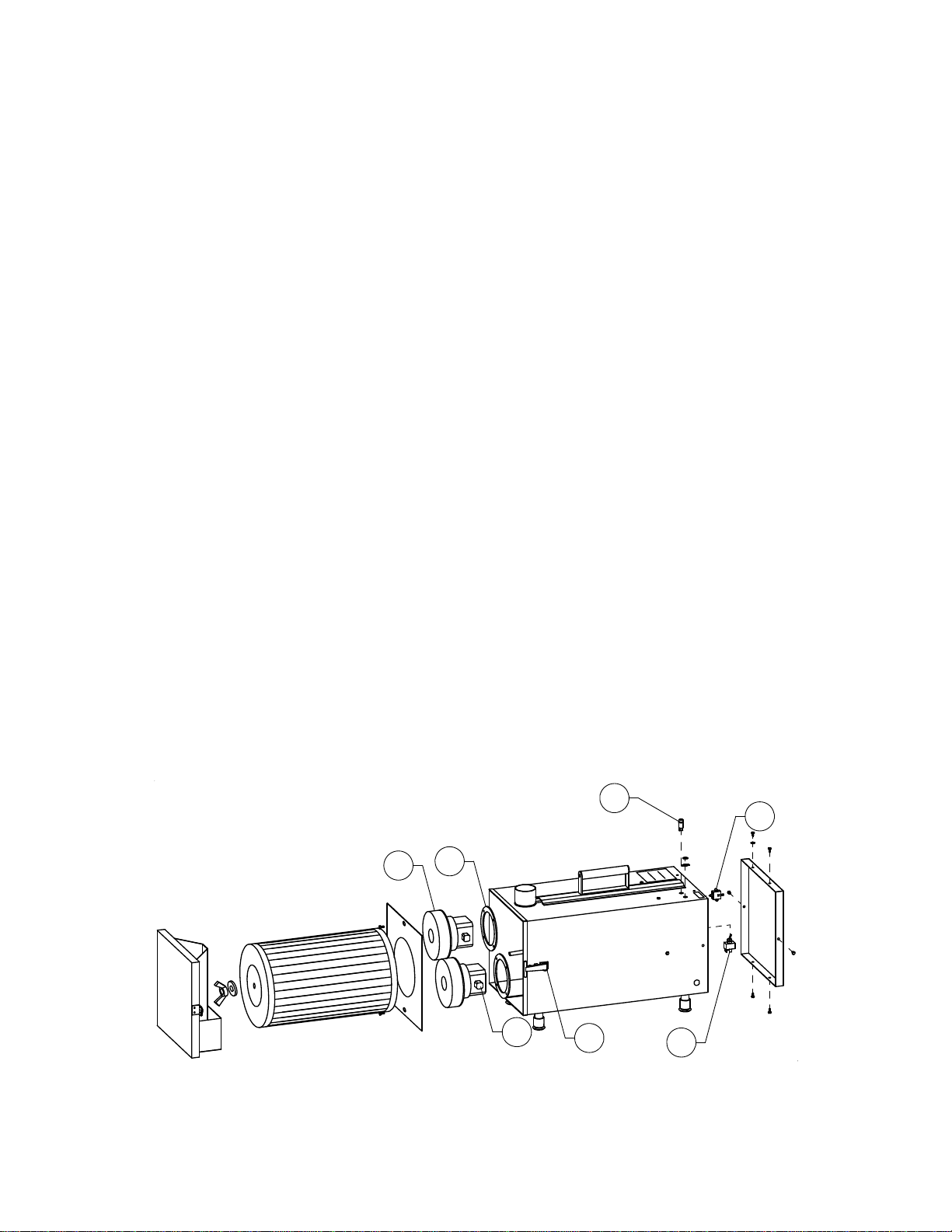
MAINTENANCE & REPLACEMENT PARTS:
WING NUT 1/4-20
(2 EA)
FLAT FIBER WASHER
(2 EA) FLEX TUBE ASSY
(1 EA)
HEX HEAD BOLT 1/4-20 X 3/4
(1 EA)
SPLIT-LOCK WASHER 1/4"
(2 EA)
BRACKET HOSE SUPPORT
(1 EA)
SUPPORT LEG
(1 EA)
MAGNETIC BASE
(1 EA)
STEEL FLAT WASHER 1/4"
(1 EA)
HEX NUT 1/4-20 KEPS
(1 EA)
RECTANGULAR NOZZLE
(1 EA)
Figure 2
FILTER:
As previously stated in the "Theory of Operation"
section of this manual, the "clogged" filter indicator
light will light whenever the differential pressure across
the filter indicates that the filter is clogged. When
opening the unit, there are no vacuum hoses to
disconnect since the pressure sensing is accomplished
by measuring at the inlet and inside the suction
chamber. The differential pressure trip point is preset
and is not field adjustable.
When the filter gets dirty, it needs to be replaced with a
new one or the filter can be cleaned. To clean, take the
filter out of the unit and hold the filter 2 to 3 inches
above a concrete floor and drop the filter and rotate it
until most of the dirt falls out of the filter or the filter can
be vacuumed with a portable air vac (If needed, order
80-201MD). To re-assemble, use reverse process to
remove filter and sweep up dirt that is on the floor.
REPLACEMENT FILTER
Cartridge Filter .....................................................65250
MAINTENANCE:
WARNING: MAINTENANCE ON THIS UNIT SHOULD
BE PERFORMED ONLY BY QUALIFIED, TRAINED
TECHNICIANS.
1. Motor Brushes- Motor brushes are available from
the company by ordering PART NUMBER 65007.
The use of high performance ball sleeve motors
provide about 500 hours of brush operation
(depending upon filter condition). Brushes should
be periodically checked after 500 hours use and if
worn, replace as a matter or preventative
maintenance.
2. Vacuum Motors- Motors are available from the
factory by ordering PART NUMBER 65001. These
motor are thermally protected by an automatic
reset thermal circuit breaker and will shut down if
they are overheated due to lack of air flow or
locked rotor condition.
DO NOT REPLACE THESE MOTORS WITH A
MOTOR THAT DOES NOT HAVE A THERMAL
OVERLOAD!

REPAIR PARTS
(1) Motor w/screws..........................................65001
(2) Motor Gasket..............................................65002
(3) Rubber Latch..............................................65003
(4) Clogged Filter Indictor Light.......................65004
(5) ON/OFF Toggle Switch..............................65005
(6) Differential Pressure Switch.......................65006
(7) Motor Brushes............................................65077
ACCESSORIES
The following accessories and attachments are
available from the factory of from your Ace dealer.
Flex Tube.............................................................65012
Magnetic Base .....................................................65014
10’ Extension Hose & Coupling ...........................65017
Slot Nozzle...........................................................65019
20” Slot Nozzle.....................................................65036
“T” Adapter...........................................................65040
Reducer, 1-1/4” (Smoke Extracting Gun).............65041
Reducer, 1-1/2” (Smoke Extracting Gun).............65043
Power-Matic Inductive Switch.............................99-800
R
M
M
OFF ON
VACUUM
SWITCH
VACUUM MOTOR #1
VACUUM MOTOR #2
"CLOGGED" FILTER
POWER SWITCH
Figure 3
SCHEMATIC WIRING DIAGRAM
ACE INDUSTRIAL PRODUCTS
By Associated Equipment Corporation
5043 Farlin Avenue
St. Louis, MO 63115
Tel. (314) 385-5178 Fax. (314) 385-3254
www.aceindustrialproducts.com
W2051 9199-0009 Rev. 20100202
4
Other Ace Ventilation Hood manuals