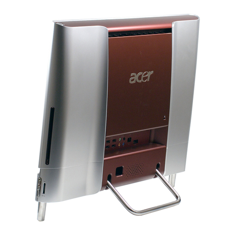
Acer Aspire Z1100 User manual

i
SERVICE GUIDE
Aspire Z1100

ii
Revision History
Refer to the following table for the updates made to this service guide.
Service guide files and updates are available on the ACER/CSD Website. For more
information, go to http://csd.acer.com.tw.The information in this guide is subject to change
without notice.
Copyright
Copyright © 2011 by Gateway Incorporated. All rights reserved. No part of this publication may
be reproduced, transmitted, transcribed, stored in a retrieval system, or translated into any
language or computer language, in any form or by any means, electronic, mechanical,
magnetic, optical, chemical, manual or otherwise, without the prior written permission of
Gateway Incorporated.
Disclaimer
The information in this guide is subject to change without notice.
There are no representations or warranties, either expressed or implied, with respect to the
contents hereof and specifically disclaims any warranties of merchantability or fitness for any
particular purpose. The software described in this manual is sold or licensed "as is". Should
the programs prove defective following their purchase, the buyer (not the manufacturer,
distributor, or its dealer) assumes the entire cost of all necessary servicing, repair, and any
incidental or consequential damages resulting from any defect in the software.
Date Chapter Updates

iii
Conventions
The following conventions are used in this manual:
WARNING:
!
Indicates a potential for personal injury.
CAUTION:
!
Indicates a potential loss of data or damage to equipment.
IMPORTANT:
+
Indicates information that is important to know for the proper completion of a
procedure, choice of an option, or completing a task.
IMPORTANT:
+
Follow local regulations for battery and circuit board disposal. Batteries and
Circuit Boards >10 cm² have been highlighted with a yellow rectangle.
The following typographical conventions are used in this document:
Book titles, directory names, file names, path names, and program/process names are
shown in italics.
Example:
the DRS5 User's Guide
/usr/local/bin/fd
the /TPH15spool_M program
Computer output (text that represents information displayed on a computer screen,
such as menus, prompts, responses to input, and error messages) are shown in
constant width.
Example:
[01] The server has been stopped
User input (text that represents information entered by a computer user, such as
command names, option letters, and words) are shown in constant width bold.
Variables contained within user input are shown in angle brackets (< >).
Example:
At the prompt, type run <file name> -m
Keyboard keys are shown in bold italics.
Example:
After entering data, press Enter.

iv
General Information 0
This service guide provides all technical information relating to the basic configuration for
Gateway global product offering. To better fit local market requirements and enhance product
competitiveness, your regional office may have decided to extend the functionality of a
machine (such as add-on cards, modems, or extra memory capabilities). These localized
features are not covered in this generic service guide. In such cases, contact your regional
offices or the responsible personnel/channel to provide further technical details.
When ordering FRU parts:
Check the most up-to-date information available on your regional Web or channel. If, for
whatever reason, a part number change is made, it may not be noted in this printed service
guide.
Acer-authorized Service Providers:
Your Acer office may have a different part number code than those given in the FRU list in this
service guide. The list provided by your regional Acer office must be used to order FRU parts
for repair and service of customer machines.

v
CHAPTER 1
Hardware Specifications
Features . . . . . . . . . . . . . . . . . . . . . . . . . . . . . . . . . . . . . . . . . . . . 1-5
Operating System. . . . . . . . . . . . . . . . . . . . . . . . . . . . . . . . . . 1-5
CPU and Chipset . . . . . . . . . . . . . . . . . . . . . . . . . . . . . . . . . . . 1-5
Memory. . . . . . . . . . . . . . . . . . . . . . . . . . . . . . . . . . . . . . . . . . 1-5
Graphics . . . . . . . . . . . . . . . . . . . . . . . . . . . . . . . . . . . . . . . . . 1-5
Display. . . . . . . . . . . . . . . . . . . . . . . . . . . . . . . . . . . . . . . . . . . 1-5
Audio. . . . . . . . . . . . . . . . . . . . . . . . . . . . . . . . . . . . . . . . . . . . 1-5
Storage . . . . . . . . . . . . . . . . . . . . . . . . . . . . . . . . . . . . . . . . . . 1-6
Optical Media Drive . . . . . . . . . . . . . . . . . . . . . . . . . . . . . . . . 1-6
Communication . . . . . . . . . . . . . . . . . . . . . . . . . . . . . . . . . . . 1-6
TV Tuner . . . . . . . . . . . . . . . . . . . . . . . . . . . . . . . . . . . . . . . . . 1-6
Card Reader . . . . . . . . . . . . . . . . . . . . . . . . . . . . . . . . . . . . . . 1-6
I/O Ports. . . . . . . . . . . . . . . . . . . . . . . . . . . . . . . . . . . . . . . . . . 1-7
Adapter . . . . . . . . . . . . . . . . . . . . . . . . . . . . . . . . . . . . . . . . . . 1-7
Dimension and Weight . . . . . . . . . . . . . . . . . . . . . . . . . . . . . 1-7
System compliance . . . . . . . . . . . . . . . . . . . . . . . . . . . . . . . . . 1-7
Certification . . . . . . . . . . . . . . . . . . . . . . . . . . . . . . . . . . . . . . 1-7
Environment . . . . . . . . . . . . . . . . . . . . . . . . . . . . . . . . . . . . . . 1-7
Accessories . . . . . . . . . . . . . . . . . . . . . . . . . . . . . . . . . . . . . . . 1-8
Software . . . . . . . . . . . . . . . . . . . . . . . . . . . . . . . . . . . . . . . . . 1-8
Computer Tour. . . . . . . . . . . . . . . . . . . . . . . . . . . . . . . . . . . . . . . 1-9
Front View . . . . . . . . . . . . . . . . . . . . . . . . . . . . . . . . . . . . . . . 1-9
Left View. . . . . . . . . . . . . . . . . . . . . . . . . . . . . . . . . . . . . . . . . 1-10
Right View . . . . . . . . . . . . . . . . . . . . . . . . . . . . . . . . . . . . . . . 1-11
Rear View . . . . . . . . . . . . . . . . . . . . . . . . . . . . . . . . . . . . . . . . 1-12
Using the Keyboard . . . . . . . . . . . . . . . . . . . . . . . . . . . . . . . . 1-13
Windows Keys. . . . . . . . . . . . . . . . . . . . . . . . . . . . . . . . . . . . . 1-14
Hotkeys . . . . . . . . . . . . . . . . . . . . . . . . . . . . . . . . . . . . . . . . . . 1-15
System Block Diagram . . . . . . . . . . . . . . . . . . . . . . . . . . . . . . . . . 1-17
Specification Tables . . . . . . . . . . . . . . . . . . . . . . . . . . . . . . . . . . . 1-18
Computer specifications . . . . . . . . . . . . . . . . . . . . . . . . . . . . . 1-18
System Board Major Chips . . . . . . . . . . . . . . . . . . . . . . . . . . . 1-19
Processor. . . . . . . . . . . . . . . . . . . . . . . . . . . . . . . . . . . . . . . . . 1-19
Processor Specifications . . . . . . . . . . . . . . . . . . . . . . . . . . . . . 1-19
CPU Fan True Value Table (Tj=90). . . . . . . . . . . . . . . . . . . . . 1-20
System Memory. . . . . . . . . . . . . . . . . . . . . . . . . . . . . . . . . . . . 1-20
Memory Combinations. . . . . . . . . . . . . . . . . . . . . . . . . . . . . . . 1-20
Video Interface. . . . . . . . . . . . . . . . . . . . . . . . . . . . . . . . . . . . . 1-21
BIOS . . . . . . . . . . . . . . . . . . . . . . . . . . . . . . . . . . . . . . . . . . . . 1-21
LAN Interface. . . . . . . . . . . . . . . . . . . . . . . . . . . . . . . . . . . . . . 1-21
Hard Disk Drive (AVL components). . . . . . . . . . . . . . . . . . . . . 1-22
Super-Multi Drive. . . . . . . . . . . . . . . . . . . . . . . . . . . . . . . . . . . 1-24

vi
LED 20” . . . . . . . . . . . . . . . . . . . . . . . . . . . . . . . . . . . . . . . . . . 1-25
LCD Inverter . . . . . . . . . . . . . . . . . . . . . . . . . . . . . . . . . . . . . . 1-26
Display Supported Resolution (LCD Supported Resolution). . 1-26
Graphics Controller . . . . . . . . . . . . . . . . . . . . . . . . . . . . . . . . . 1-26
Display Supported Resolution (GPU Supported Resolution). . 1-27
Camera . . . . . . . . . . . . . . . . . . . . . . . . . . . . . . . . . . . . . . . . . . 1-27
Mini Card . . . . . . . . . . . . . . . . . . . . . . . . . . . . . . . . . . . . . . . . . 1-27
Audio Codec and Amplifier . . . . . . . . . . . . . . . . . . . . . . . . . . . 1-28
Audio Interface. . . . . . . . . . . . . . . . . . . . . . . . . . . . . . . . . . . . . 1-28
Wireless Module - 802.11 b/g/n (optional). . . . . . . . . . . . . . . . 1-29
VRAM . . . . . . . . . . . . . . . . . . . . . . . . . . . . . . . . . . . . . . . . . . . 1-29
USB Port . . . . . . . . . . . . . . . . . . . . . . . . . . . . . . . . . . . . . . . . . 1-30
AC Adapter . . . . . . . . . . . . . . . . . . . . . . . . . . . . . . . . . . . . . . . 1-30
System Power Management . . . . . . . . . . . . . . . . . . . . . . . . . . 1-31
Card Reader . . . . . . . . . . . . . . . . . . . . . . . . . . . . . . . . . . . . . . 1-31
System LED Indicator . . . . . . . . . . . . . . . . . . . . . . . . . . . . . . . 1-31
CHAPTER 2
System Utilities
BIOS Setup Utility. . . . . . . . . . . . . . . . . . . . . . . . . . . . . . . . . . . . . 2-3
Navigating the BIOS Utility . . . . . . . . . . . . . . . . . . . . . . . . . . 2-3
BIOS . . . . . . . . . . . . . . . . . . . . . . . . . . . . . . . . . . . . . . . . . . . . . . . 2-4
Main . . . . . . . . . . . . . . . . . . . . . . . . . . . . . . . . . . . . . . . . . . . . 2-4
Advanced . . . . . . . . . . . . . . . . . . . . . . . . . . . . . . . . . . . . . . . . 2-6
Power . . . . . . . . . . . . . . . . . . . . . . . . . . . . . . . . . . . . . . . . . . . 2-7
Security . . . . . . . . . . . . . . . . . . . . . . . . . . . . . . . . . . . . . . . . . . 2-8
Boot Options. . . . . . . . . . . . . . . . . . . . . . . . . . . . . . . . . . . . . . 2-13
Exit. . . . . . . . . . . . . . . . . . . . . . . . . . . . . . . . . . . . . . . . . . . . . . 2-14
BIOS Flash Utilities . . . . . . . . . . . . . . . . . . . . . . . . . . . . . . . . . . . . 2-15
DOS Flash Utility. . . . . . . . . . . . . . . . . . . . . . . . . . . . . . . . . . . 2-16
Wflash4M Utility. . . . . . . . . . . . . . . . . . . . . . . . . . . . . . . . . . . 2-17
Clearing BIOS Passwords . . . . . . . . . . . . . . . . . . . . . . . . . . . . . . . 2-20
Using DMI Tools . . . . . . . . . . . . . . . . . . . . . . . . . . . . . . . . . . . . . . 2-22
Using the LAN MAC EEPROM Utility. . . . . . . . . . . . . . . . . . . . . . 2-24

vii
CHAPTER 3
Machine Maintenance Procedures
Introduction . . . . . . . . . . . . . . . . . . . . . . . . . . . . . . . . . . . . . . . . . 3-5
General Information . . . . . . . . . . . . . . . . . . . . . . . . . . . . . . . . . . 3-5
Recommended Equipment . . . . . . . . . . . . . . . . . . . . . . . . . . . . . 3-5
Screw Table . . . . . . . . . . . . . . . . . . . . . . . . . . . . . . . . . . . . . . . . . 3-6
Maintenance Flowchart. . . . . . . . . . . . . . . . . . . . . . . . . . . . . . . . 3-7
Getting Started . . . . . . . . . . . . . . . . . . . . . . . . . . . . . . . . . . . . . . 3-8
Dummy Card Removal . . . . . . . . . . . . . . . . . . . . . . . . . . . . . . 3-9
Dummy Card Installation . . . . . . . . . . . . . . . . . . . . . . . . . . . . 3-9
Rear Stand Removal . . . . . . . . . . . . . . . . . . . . . . . . . . . . . . . . 3-10
Rear Stand Installation. . . . . . . . . . . . . . . . . . . . . . . . . . . . . . 3-11
Back cover Removal . . . . . . . . . . . . . . . . . . . . . . . . . . . . . . . . 3-12
Back Cover Installation. . . . . . . . . . . . . . . . . . . . . . . . . . . . . . 3-13
Function board Removal . . . . . . . . . . . . . . . . . . . . . . . . . . . . 3-14
Function board Installation . . . . . . . . . . . . . . . . . . . . . . . . . . 3-15
Converter Board Removal . . . . . . . . . . . . . . . . . . . . . . . . . . . 3-16
Converter Board Installation . . . . . . . . . . . . . . . . . . . . . . . . . 3-16
Change Board Removal . . . . . . . . . . . . . . . . . . . . . . . . . . . . . 3-17
Change Board Installation . . . . . . . . . . . . . . . . . . . . . . . . . . . 3-17
Power Board Removal . . . . . . . . . . . . . . . . . . . . . . . . . . . . . . 3-18
Power Board Installation . . . . . . . . . . . . . . . . . . . . . . . . . . . . 3-18
Infrared Board Removal. . . . . . . . . . . . . . . . . . . . . . . . . . . . . 3-19
Infrared Board Installation . . . . . . . . . . . . . . . . . . . . . . . . . . 3-20
HDD Module Removal . . . . . . . . . . . . . . . . . . . . . . . . . . . . . . 3-21
HDD Module Installation . . . . . . . . . . . . . . . . . . . . . . . . . . . . 3-22
HDD Bracket Removal . . . . . . . . . . . . . . . . . . . . . . . . . . . . . . 3-23
HDD Bracket Installation . . . . . . . . . . . . . . . . . . . . . . . . . . . . 3-23
ODD Module Removal . . . . . . . . . . . . . . . . . . . . . . . . . . . . . . 3-24
ODD Module Installation. . . . . . . . . . . . . . . . . . . . . . . . . . . . 3-26
Button Board Removal. . . . . . . . . . . . . . . . . . . . . . . . . . . . . . 3-27
Button Board Installation . . . . . . . . . . . . . . . . . . . . . . . . . . . 3-28
Camera Module Removal. . . . . . . . . . . . . . . . . . . . . . . . . . . . 3-29
Camera Module Installation . . . . . . . . . . . . . . . . . . . . . . . . . 3-31
Mainboard Shielding Removal . . . . . . . . . . . . . . . . . . . . . . . 3-32
Mainboard Shielding Installation . . . . . . . . . . . . . . . . . . . . . 3-33
DIMM Module Removal. . . . . . . . . . . . . . . . . . . . . . . . . . . . . 3-34
DIMM Module Installation. . . . . . . . . . . . . . . . . . . . . . . . . . . 3-34
WLAN Module Removal. . . . . . . . . . . . . . . . . . . . . . . . . . . . . 3-35
WLAN Module Installation . . . . . . . . . . . . . . . . . . . . . . . . . . 3-35
TV Tuner Module Removal . . . . . . . . . . . . . . . . . . . . . . . . . . 3-36
TV Tuner Module Installation . . . . . . . . . . . . . . . . . . . . . . . . 3-36
RTC Battery Removal . . . . . . . . . . . . . . . . . . . . . . . . . . . . . . . 3-37
RTC Battery Installation . . . . . . . . . . . . . . . . . . . . . . . . . . . . . 3-37

viii
Fan Module Removal . . . . . . . . . . . . . . . . . . . . . . . . . . . . . . . 3-38
Fan Module Installation. . . . . . . . . . . . . . . . . . . . . . . . . . . . . 3-38
ODD Connector Removal . . . . . . . . . . . . . . . . . . . . . . . . . . . . 3-39
ODD Connector Installation. . . . . . . . . . . . . . . . . . . . . . . . . . 3-39
Thermal Module Removal . . . . . . . . . . . . . . . . . . . . . . . . . . . 3-40
Thermal Module Installation . . . . . . . . . . . . . . . . . . . . . . . . . 3-41
CPU Removal. . . . . . . . . . . . . . . . . . . . . . . . . . . . . . . . . . . . . . 3-42
CPU Installation . . . . . . . . . . . . . . . . . . . . . . . . . . . . . . . . . . . 3-43
Mainboard Removal. . . . . . . . . . . . . . . . . . . . . . . . . . . . . . . . 3-44
Mainboard Installation . . . . . . . . . . . . . . . . . . . . . . . . . . . . . 3-46
Middle Frame Removal . . . . . . . . . . . . . . . . . . . . . . . . . . . . . 3-48
Middle Frame Installation . . . . . . . . . . . . . . . . . . . . . . . . . . . 3-50
LCD Panel Removal. . . . . . . . . . . . . . . . . . . . . . . . . . . . . . . . . 3-51
LCD Panel Installation . . . . . . . . . . . . . . . . . . . . . . . . . . . . . . 3-53
Speaker Module Removal . . . . . . . . . . . . . . . . . . . . . . . . . . . 3-54
Speaker Module Installation . . . . . . . . . . . . . . . . . . . . . . . . . 3-54
LED Board Removal . . . . . . . . . . . . . . . . . . . . . . . . . . . . . . . . 3-55
LED Board Installation . . . . . . . . . . . . . . . . . . . . . . . . . . . . . . 3-55
CHAPTER 4
Troubleshooting
Introduction . . . . . . . . . . . . . . . . . . . . . . . . . . . . . . . . . . . . . . . . . 4-3
General Information . . . . . . . . . . . . . . . . . . . . . . . . . . . . . . . . . . 4-3
Common Problems . . . . . . . . . . . . . . . . . . . . . . . . . . . . . . . . . 4-4
LCD Failure . . . . . . . . . . . . . . . . . . . . . . . . . . . . . . . . . . . . . . . 4-5
Wireless Function Failure. . . . . . . . . . . . . . . . . . . . . . . . . . . . 4-8
Component Failure. . . . . . . . . . . . . . . . . . . . . . . . . . . . . . . . . 4-9
Other Functions Failure . . . . . . . . . . . . . . . . . . . . . . . . . . . . . 4-11
Intermittent Problems . . . . . . . . . . . . . . . . . . . . . . . . . . . . . . . . . 4-16
Undetermined Problems . . . . . . . . . . . . . . . . . . . . . . . . . . . . . . . 4-16
BIOS Post Codes . . . . . . . . . . . . . . . . . . . . . . . . . . . . . . . . . . . . . . 4-17
CHAPTER 5
Jumper and Connector Locations
Mainboard . . . . . . . . . . . . . . . . . . . . . . . . . . . . . . . . . . . . . . . . . . 5-3
Clearing Password and BIOS Recovery . . . . . . . . . . . . . . . . . . . . 5-5
Clearing Password . . . . . . . . . . . . . . . . . . . . . . . . . . . . . . . . . 5-5
BIOS Recovery by Crisis Disk. . . . . . . . . . . . . . . . . . . . . . . . . . 5-6

ix
CHAPTER 6
FRU (Field Replaceable Unit) List
Exploded Diagrams . . . . . . . . . . . . . . . . . . . . . . . . . . . . . . . . . . . 6-4
Main Assembly . . . . . . . . . . . . . . . . . . . . . . . . . . . . . . . . . . . . 6-4
FRU List . . . . . . . . . . . . . . . . . . . . . . . . . . . . . . . . . . . . . . . . . . . . . 6-6
Screw List . . . . . . . . . . . . . . . . . . . . . . . . . . . . . . . . . . . . . . . . . . . 6-13
CHAPTER 7
Online Support Information
Introduction . . . . . . . . . . . . . . . . . . . . . . . . . . . . . . . . . . . . . . . . . 7-3

x

CHAPTER 1
Hardware Specifications

1-2
Features . . . . . . . . . . . . . . . . . . . . . . . . . . . . . . . . . . . . . . . . . . . . 1-5
Operating System. . . . . . . . . . . . . . . . . . . . . . . . . . . . . . . . . . 1-5
CPU and Chipset . . . . . . . . . . . . . . . . . . . . . . . . . . . . . . . . . . . 1-5
Memory. . . . . . . . . . . . . . . . . . . . . . . . . . . . . . . . . . . . . . . . . . 1-5
Graphics . . . . . . . . . . . . . . . . . . . . . . . . . . . . . . . . . . . . . . . . . 1-5
Display. . . . . . . . . . . . . . . . . . . . . . . . . . . . . . . . . . . . . . . . . . . 1-5
Audio. . . . . . . . . . . . . . . . . . . . . . . . . . . . . . . . . . . . . . . . . . . . 1-5
Storage . . . . . . . . . . . . . . . . . . . . . . . . . . . . . . . . . . . . . . . . . . 1-6
Optical Media Drive . . . . . . . . . . . . . . . . . . . . . . . . . . . . . . . . 1-6
Communication . . . . . . . . . . . . . . . . . . . . . . . . . . . . . . . . . . . 1-6
TV Tuner . . . . . . . . . . . . . . . . . . . . . . . . . . . . . . . . . . . . . . . . . 1-6
Card Reader . . . . . . . . . . . . . . . . . . . . . . . . . . . . . . . . . . . . . . 1-6
I/O Ports. . . . . . . . . . . . . . . . . . . . . . . . . . . . . . . . . . . . . . . . . . 1-7
Adapter . . . . . . . . . . . . . . . . . . . . . . . . . . . . . . . . . . . . . . . . . . 1-7
Dimension and Weight . . . . . . . . . . . . . . . . . . . . . . . . . . . . . 1-7
System compliance . . . . . . . . . . . . . . . . . . . . . . . . . . . . . . . . . 1-7
Certification . . . . . . . . . . . . . . . . . . . . . . . . . . . . . . . . . . . . . . 1-7
Environment . . . . . . . . . . . . . . . . . . . . . . . . . . . . . . . . . . . . . . 1-7
Accessories . . . . . . . . . . . . . . . . . . . . . . . . . . . . . . . . . . . . . . . 1-8
Software . . . . . . . . . . . . . . . . . . . . . . . . . . . . . . . . . . . . . . . . . 1-8
Computer Tour. . . . . . . . . . . . . . . . . . . . . . . . . . . . . . . . . . . . . . . 1-9
Front View . . . . . . . . . . . . . . . . . . . . . . . . . . . . . . . . . . . . . . . 1-9
Left View. . . . . . . . . . . . . . . . . . . . . . . . . . . . . . . . . . . . . . . . . 1-10
Right View . . . . . . . . . . . . . . . . . . . . . . . . . . . . . . . . . . . . . . . 1-11
Rear View . . . . . . . . . . . . . . . . . . . . . . . . . . . . . . . . . . . . . . . . 1-12
Using the Keyboard . . . . . . . . . . . . . . . . . . . . . . . . . . . . . . . . 1-13
Windows Keys. . . . . . . . . . . . . . . . . . . . . . . . . . . . . . . . . . . . . 1-14
Hotkeys . . . . . . . . . . . . . . . . . . . . . . . . . . . . . . . . . . . . . . . . . . 1-15
System Block Diagram . . . . . . . . . . . . . . . . . . . . . . . . . . . . . . . . . 1-17
Specification Tables . . . . . . . . . . . . . . . . . . . . . . . . . . . . . . . . . . . 1-18
Computer specifications . . . . . . . . . . . . . . . . . . . . . . . . . . . . . 1-18
System Board Major Chips . . . . . . . . . . . . . . . . . . . . . . . . . . . 1-19
Processor. . . . . . . . . . . . . . . . . . . . . . . . . . . . . . . . . . . . . . . . . 1-19
Processor Specifications . . . . . . . . . . . . . . . . . . . . . . . . . . . . . 1-19
CPU Fan True Value Table (Tj=90). . . . . . . . . . . . . . . . . . . . . 1-20
System Memory. . . . . . . . . . . . . . . . . . . . . . . . . . . . . . . . . . . . 1-20
Memory Combinations. . . . . . . . . . . . . . . . . . . . . . . . . . . . . . . 1-20
Video Interface. . . . . . . . . . . . . . . . . . . . . . . . . . . . . . . . . . . . . 1-21
BIOS . . . . . . . . . . . . . . . . . . . . . . . . . . . . . . . . . . . . . . . . . . . . 1-21
LAN Interface. . . . . . . . . . . . . . . . . . . . . . . . . . . . . . . . . . . . . . 1-21
Hard Disk Drive (AVL components). . . . . . . . . . . . . . . . . . . . . 1-22
Super-Multi Drive. . . . . . . . . . . . . . . . . . . . . . . . . . . . . . . . . . . 1-24
LED 20” . . . . . . . . . . . . . . . . . . . . . . . . . . . . . . . . . . . . . . . . . . 1-25
LCD Inverter . . . . . . . . . . . . . . . . . . . . . . . . . . . . . . . . . . . . . . 1-26
Display Supported Resolution (LCD Supported Resolution). . 1-26
Graphics Controller . . . . . . . . . . . . . . . . . . . . . . . . . . . . . . . . . 1-26

1-3
Display Supported Resolution (GPU Supported Resolution). . 1-27
Camera . . . . . . . . . . . . . . . . . . . . . . . . . . . . . . . . . . . . . . . . . . 1-27
Mini Card . . . . . . . . . . . . . . . . . . . . . . . . . . . . . . . . . . . . . . . . . 1-27
Audio Codec and Amplifier . . . . . . . . . . . . . . . . . . . . . . . . . . . 1-28
Audio Interface. . . . . . . . . . . . . . . . . . . . . . . . . . . . . . . . . . . . . 1-28
Wireless Module - 802.11 b/g/n (optional). . . . . . . . . . . . . . . . 1-29
VRAM . . . . . . . . . . . . . . . . . . . . . . . . . . . . . . . . . . . . . . . . . . . 1-29
USB Port . . . . . . . . . . . . . . . . . . . . . . . . . . . . . . . . . . . . . . . . . 1-30
AC Adapter . . . . . . . . . . . . . . . . . . . . . . . . . . . . . . . . . . . . . . . 1-30
System Power Management . . . . . . . . . . . . . . . . . . . . . . . . . . 1-31
Card Reader . . . . . . . . . . . . . . . . . . . . . . . . . . . . . . . . . . . . . . 1-31
System LED Indicator . . . . . . . . . . . . . . . . . . . . . . . . . . . . . . . 1-31

1-4

Hardware Specifications and Configurations 1-5
Hardware Specifications and Configurations
Features 0
The following is a summary of the computer’s many features:
Operating System 0
Genuine Windows®7 Home Premium 64-bit
Genuine Windows®7 Home Basic 64-bit
CPU and Chipset 0
AMD E350 Fusion™ APU, dual-core (18 W)
AMD Hudson-D1 Chipset
Memory 0
Dual-channel 1333 MHz DDR3 SO-DIMM support:
Up to 2 GB per memory module
Upgrade option with 2 DIMM slots
Graphics 0
AMD Graphics technology
Microsoft®DirectX®11
Display 0
ZX4250/ZX4251 0
20" 1600 x 900 resolution
High brightness (250-nit)
LED backlight type
5 ms response time
16:9 aspect ratio
ZX4251 0
Optical touch solution
Audio 0
Creative®THX®TruStudio PC™, featuring TruStudio Surround, TruStudio Crystalizer,
TruStudio Speaker, TruStudio Dialog Plus, TruStudio Smart Volume
High-definition audio

1-6 Hardware Specifications and Configurations
Built-in microphone
Integrated 2 W stereo speaker system
Storage 0
Serial ATA hard disk up to 1.5 TB
Optical Media Drive 0
SuperMulti
Communication 0
WLAN:
802.11 b/g/n Wi-Fi CERTIFIED™
LAN:
Gigabit Ethernet
Webcam:
2.0 MP stand-alone webcam with 1600 x 1200 resolution
TV Tuner 0
Acer TV-tuner options:
Hybrid TV-tuner supporting worldwide analog/DVB-T (Digital Video
Broadcasting-Terrestrial)
Hybrid TV-tuner supporting worldwide analog and ATSC (Advanced Television
Systems Committee)
TV-tuner I/O:
RF-in jack for digital/TV antenna cable input
Card Reader 0
Multi-in-1 card reader, supporting:
MultiMediaCard (MMC)
Secure Digital™ (SD) Card
SDHC™ Card
Memory Stick™
Memory Stick PRO Duo™
Memory Stick PRO-HG Duo™

Hardware Specifications and Configurations 1-7
I/O Ports 0
Side:
Two USB 2.0 ports
Multi-in-1 card reader
Headphone and microphone line-out jack
Back:
Four USB 2.0 ports
One audio jack
Ethernet (RJ-45) port
TV-tuner (optional)
Adapter 0
90 W adapter with power cord
Dimension and Weight 0
Dimensions
485 (H) x 382 (W) x 70.1 (D) mm [19.09 (H) x 15.04 (W) x 2.76 (D) inch]
Weight
ZX4250 0
5.62 kg (12.39 lbs)
ZX4251 0
6.5 kg (14.33 lbs)
System compliance 0
PC 2001
Certification 0
CE, Nemko
Environment 0
Temperature:
Operating: +5°C to +35°C (+41°F to +95°F)
Non-operating: -20°C to +60°C (-4°F to +140°F)
Humidity (non-condensing):
Operating: 15% to 80% RH, non-condensing
Non-operating: 10% to 90% RH, non-condensing at 40°C (104°F)

1-8 Hardware Specifications and Configurations
Accessories 0
Gateway Wireless / USB keyboard and mouse
Software 0
Productivity
ZX4250/ZX4251 0
Adobe®Reader®
Microsoft®Office 2010 preloaded (purchase a product key to activate)
Windows Live™ Essentials
Norton™ Online Backup Trial
Adobe®Photoshop®Elements 9
ZX4251 0
Microsoft®Office Starter 2010
Internet
Adobe®Flash®Player
Bing™ Bar
Skype™
Multimedia
Nero®10 Essentials
Cyberlink®YouCam
Security
Norton Internet Security™ 2011 Gateway Edition
Entertainment
Wild Tangent WW Gateway Edition
Utilities
Gateway Recovery Management

Hardware Specifications and Configurations 1-9
Computer Tour 0
Front View 0
Figure 1-1. Front View
Table 1-1. Front View
# Icon ItemDescription
1 Integrated Webcam Web camera for video communication.
2 Display Screen Also called Liquid-Crystal Display (LCD), displays
computer output (configuration may vary by
model).
3 Power Button/Indicator Turns the computer on and off. Indicates the
computer's power status.

1-10 Hardware Specifications and Configurations
Left View 0
Figure 1-2. Left View
Table 1-2. Left View
#Icon Item Description
1 Multi-in-1 card reader Accepts Secure Digital (SD), MultiMediaCard
(MMC), Memory Stick PRO (MS PRO), xD-Picture
Card (xD).
NOTE:
Push to remove/install the card. Only one card
can operate at any time.
2 USB 2.0 Ports Connect to USB 2.0 devices (e.g., USB mouse,
USB camera, USB keyboard).
3 Headphones/Speaker
Jack Connects to audio devices (e.g., speakers,
headphones).
Microphone Jack Accepts inputs from external microphones.
1
2
3
Table of contents
Other Acer Desktop manuals

Acer
Acer Power FV Configuration guide

Acer
Acer Aspire SA80 User manual

Acer
Acer Predator Orion 5000 User manual

Acer
Acer ConceptD 300 User manual

Acer
Acer Aspire 6600 User manual

Acer
Acer Aspire T100 User manual

Acer
Acer VERITON 7200 User manual

Acer
Acer Aspire M3202 User manual

Acer
Acer Aspire XC-1760 I5202 User manual

Acer
Acer Aspire L series User manual

Acer
Acer AcerPower M4 User manual

Acer
Acer Aspire T300 User manual

Acer
Acer Veriton M678G Installation instructions

Acer
Acer Veriton 3600GT User manual

Acer
Acer Veriton S4660G User manual

Acer
Acer AcerPower F2 User manual

Acer
Acer Aspire T320 User manual

Acer
Acer AcerPower 8400 User manual

Acer
Acer Aspire T670 User manual

Acer
Acer Veriton Fpi User manual