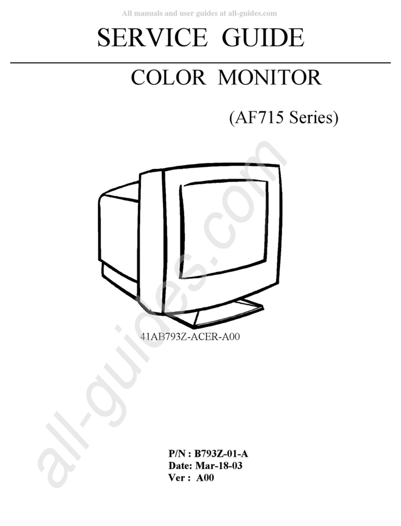
Acer AC501 User manual

1
WARNING............................................................................................................................2
1. ALGNMENT PROCEDURE.............................................................................................3
A. Conditions................................................................................................................................3
B. Functions Alignment................................................................................................................3
C. Preset Timing:..........................................................................................................................6
2. OPERATION THEOREM ...............................................................................................12
A. Power Supply (1)...................................................................................................................12
B. Deflection...............................................................................................................................12
C. Video......................................................................................................................................12
D. Digital Controllable...............................................................................................................12
E. Function Block Diagram........................................................................................................13
F. Power Supply..........................................................................................................................14
G. Under Voltage Protection.......................................................................................................15
H. Degaussing CKT....................................................................................................................15
I. Deflection................................................................................................................................16
J. Video AMP. Circuit.................................................................................................................18
J-2. Video AMPLIFIER..............................................................................................................18
K. Digit Control..........................................................................................................................20
3. CONTROL AND CONMECT LAYOUT ..........................................................................21
A.Main PCB ...............................................................................................................................21
B.CRT PCB................................................................................................................................22
4. TROUBLE SHOOTING..................................................................................................23
A.Power Supply Check ..............................................................................................................23
B.Monitor Check Flow Chart.....................................................................................................24
APPENDIX A: PARTS LISTS .....................…………………………………………………...27
APPENDIX B: DISPLAY UNIT ASSEMBLY…………………………………………………...82
PPENDIX C: P.C.B. ASSEMBLY………………………………………………………………..96
APPENDIX D: CRT& YOKE ASSEMBLY…………………………………………………….106

2
WARNING
1) This product contains components which are critical for X-radiation safety. Read the Service manual carefully for
proper replacement . Maximum 2nd anode vol tage use high impedance meter, connect (-) to chassis, use a high
voltage lead from (+) to 2nd anode.
2) Critical Components are marked with the symbol of in the material list. For continued protection against X-radiation,
replace only with same type and rating components.
3) Critical Components are marked with the symbol of # i n the material list. For continued protection against Low
Radiation, replace only with same part number.

3
1. ALGNMENT PROCEDURE
A. Conditions
A-1. Equipments
Signal generator: A chroma-2250 signal generator to be provided as standard signal source.
Color analyzer: A minolta CA-100 color analyzer to be provided as standard color analyzer.
A-2. Presetting
Preset all of the VRs on main board to it’s mechanical center, and set FBT’s G2 control VR to it’s
minimum position before to proceed al ignment.
CRT faces to east direction, connects monitor and generator, warm up 30 minut es at least before to
proceed alignment.
A-3. Magnetic Environment
Unless otherwise specified, all performance tests are performed in a controlled magnetic environment,
the magnitude of the horizontal magnetic fi eld component in any direction will be less than 1000
gamma, the magnitude of t he vertical magnetic field component is defined in table 1 of engineering
specification.
B. Functions Alignment
B-1. Power Adj ust
Select timing #7 (VESA 48K 1024x768)with crosshatch pattern, adjust both horizontal and vertical
size cont rols to get display size within 262x196±1mm.
Adjust VR901 to get a DC 13.0±0.1V to be obtained on plus of C510.
Double check and make sure test points are within speci fications as defined i n following
VC930 (+) = 7.5 ± 0.5 V DC
VC942 (+) = 7.5 ± 0.3 V DC
VC943 (-) = -12 ± 1 V DC
VC946 (+) = 60 ± 2 V DC
VC947 (+) = 73 ± 2 V DC
B-2. Adjust
Select timing #6 (VESA 64K 1280x1024)with crosshatch pattern, adjust both horizontal and vertical
OSD’s size control to get display size within 262x196±1mm.
Adjust VR501 to get a DC 145±0.3 V to be obtained on FBT’s pin3.
Double check and make sure test points are within speci fications as defined i n following
Timing Mode Volt age Tol erance
#1 31.5 KHz 66.7V ±3%
#6 68.677 KHz 145V ±3%

4
B-3. Picture Alignment
White balance alignment
Select timing #6(VESA 64K 1280x1024) with crosshatch pattern, adjust both horizontal and vertical
OSD’s size control to get di splay size within 262 x 196±1mm.
Disconnect R×G×B signal inputs, adjust OSD’s brightness control to i t’s maximum position then
adjust FBT’s G2 control VR to get a DC voltage t o be obtained on CRT socket pin #7 as defined in
following
CRT type G2 Voltage
SAMSUNG 550V+/-10V
LG 550V+/-10V
B-4. White Balance Aignment
B-5. Select timing 6 VESA 1280X1024 with full field raster pattern (cut off R, G, B) Adjust H-size 260mm V-size
195mm
B-6. Brightness and Contrast set to MAX adjust G2, has G2 Voltage to be 550V, then, adjust VR502 to get raster is
0.8fl.
Adjust G DC-bias has Y=0.8FL
BDC-biashasy=311+/-25
R DC-bias has x=281 +/- 25
Adjust Brightness to raster is 0.06fl.
B-7: Select 2 inch one-square pattern, adjust color temperature 9300Celsius degree.
Adjust GDC-GainhasY=50FL+/-2FL
BDC-biashasy=311+/-5
R DC-bias has x=281 +/- 5
B-8: Select white pattern,
Double check x=281 +/-2 5
y=311 +/-2 5
Adjust SUB-Bright to get full white pattern, Y is 105 +/-3 cd/mm
B-9:Same procedure, to get
Color temperature 6500 x=313 y=329
5000 x=345 y=359
B-10. Focus alignment
B-11. Select timing #6 (VESA 64k 1280x1024) with a 2 inch five-square pattern, adjust the OSD’ s brightness control
to get raster light output equial to 0.06 F-L then adjust OSD’ s contrast control to get 35F-L at the center of center of the
screen, select an alternating “me” pattern that fills the screen with letters that white on black then adjust FBT’ s G4
control VR to get best focus on quarter position of CRT screen

5
B-12. Double check focus performance the letters must be clear, legible and uniform, if not, repeat stape 2.3.2.1 to
obtain best focus performance.
B-13. Mi sconvergence alignment
B-14. Select crosshatch pattern and then input individually input R+B and R+G signals then measure and make sure
miscongence within Center = 0. 2 mm(max.)
Zone A = 0.3 mm(max.)
Zone B = 0.4 mm(max.)
, if not, readjust 4 P and 6P on the deflection yoke to get misconvergnce within specification. Preset modes alignment
B-15. Disconnect P103 before automatic alignment or connect P103 before manual
alignment.
B-16. Turn off monitor power and plug in P103 then turn on power again to get into factory mode.
B-17. Adjust H-size/ H-phase/V-size/V-center/ pincushion/trapezoid control s…. etc., to get geometric distortion within
specification as shown in engineering specification.
B-18. If raster center can’t be adjust to get properly, P801 may sometime be necessary to reconnect in reverse direction
and then repeat step 2, 3, 4, 3 to get geometric distortion within specification.
B-19. X-ray protection test
B-20. Short P502 for 1 second at least to verify X-ray protection circuit is working properly.
B-21. Burn-in mode and power saving check
B-22. Turn off power, disconnect I/O cable and plug in P103 then turn on the power again to get into burn-in mode.
B-23. Turn off the monitor power and unplug P103 then disconnect H or V sync, turn on the power again to get into
suspend mode (power LED should indicating amber color), disconnect both H and V sync to get into off mode (power
LED should indicating amber color)

6
C. Preset Timing:
C-1. Mode : 1
Horizontal Active 640 Pixels
Vertial Active 480 Pixels
Refresh 606 Hz
Sync Polarity -,- (HSync VSync)
HORIZONTAL CHAR PIX / CHAR PIX ACTUAL UNITS
Pixel Frequency 25.1750 MHz
Pixel Period 39.7219 ns
Active 640 25.4220
s
Border 1 X8= 8 0.3178
s
Front Porch 1 X8= 8 0.3178
s
Sync Width 12 X8= 96 3.8133
s
Back Porch 5 X8= 40 1.5889
s
Total 800 31.7776
s
Horizontal Frequency 31.4688 kHz
Bordered Video 656 26.0576
s
Blanking Interval 144 5.7200
s
Blank + 2*Border 160 6.3555
s
VERTICAL CHAR PIX / CHAR LINES ACTUAL UNITS
Active 480 15.2532 ms
Border 8 X1= 8 0.2542 ms
Front Porch 3 X1= 3 0.0953 ms
Sync Width 2 X1= 2 0.0636 ms
Back Porch 24 X1= 24 0.7627 ms
Total 525 16.6832 ms
Vertical Frequency 59.9405 Hz
Bordered Video 496 15.7617 ms
Blanking Interval 29 0.9215 ms
Blank + 2*Border 45 1.4300 ms

7
C-2. Mode : 2

8
C-3. Mode : 3

9
C-4. Mode : 4

10
C-5. Mode : 5

11
C-6. Mode : 6

12
2. OPERATION THEOREM
A. Power Supply (1)
Transfer AC source to DC source that supply all the circuit power. It includes:
!"+13V: For video pre-amp circuit, parts of horizontal and vertical deflection circuit.
!"+63V: For booster circuit.
!"+7.5V: For CRT heater and u-P power.
!"+73V: For video AMP. Circuit.
!"–11.7V: For vertical deflection negative power.
B. Deflection
Produce YOKE deflect ion current of horizontal and vertical, CRT H.V and bi as that makes screen
rast er.
C. Video
Amplify the video signal and add the signal to the cathode of CRT to produce video on the screen.
D. Digital Controllable
With the EEPROM and PROGRAM, the micro-processor(u-P) control all the picture performance.
From the key control, the user can change t he H-size, V-size, R-gain¡L¡Letc.

13
E. Function Block Diagram

14
F. Power Supply
F-1. Rectifier And Filter Ckt
The 90Vac-265Vac input line voltage is rectified by D901- D904, and smoothed by C906 to provide
DC operating voltage for the circuit.
F-2. Flyback And Pwm Ckt
When power is initially applied to the circuit, C909 charges through R903, Q902.When t he voltage across C909
reaches a level of 16V, U901 is enabled, turning on Q901 and turning off Q902 to complete start-up action. During the
On-time of Q901, energy is stored in T900. At t his time the polarity of the out put windings is such that all output
rectifiers are reverse biased and no energy is transferred. Primary current is sensed by R907 and compared to a DC level
that is determined by voltage feedback. When this level is reached, Q901 is turned off and the polarity of all T900
windings reverses , forward biasing the output rectifiers. All the energy stored is now transferred to the output capacitors.
Many cycles of this store/release action are needed to charge the outputs to their respective voltages. The feedback
voltage across R931, D909 is smoothed by C911 and through cross t he divider which assembled by R914, R916, R917
and VR901 to the error amplifier (U901 pin2) and compared to an internal 2.5V reference.
F-3. Snubber Ckt
Energy stored in the leakage inductance of T900 cause a voltage spike which be added to the normal reset voltage across
T900 when Q901 turn off. The clamp consisting of D905, R904 and C907 limits this voltage excursion from exceeding
the Vds rating of Q901. In addition, a turn off snubber made up of D906, R905 and C908 keeps power dissipation in
Q901 low by delaying the voltage rise until drain current has decreased from its peak value. This snubber also damps
out any ringing which may occur due to parasitic.
F-4. Synchronized Ckt
The oscillator frequency is defined by R912 , C912. The equation is approximately : Fosc =1.8/ (R912*C912). The
external signal “FBP”
that comes from horizontal circuit can synchronize the working frequency of power circuit by through
cross R919,R918 and D911.
F-5. Power Saving Ckt
The monitor has ON, Suspend/Standby and OFF states. The monitor enters the Suspend/Standby mode if either V-sync
or H-sync signals are removed. When the machine in the Suspend/Standby State, PS1 should be low to turn off +13Vs.
In this state, input power should be less than 15W and D960 LED illuminate amber. The monitor enters OFF mode if
both H-sync and V-sync are removed. When in the OFF State, PS1 and PS2 should be low simultaneously to turn off
+13Vs and +7.5Vs outputs. In this state, input power should be less than 5W and D960 LED illuminate amber. When
the monitor wakes up from the OFF mode to the ON mode , the +13Vs will provide power to heat the heater of CRT for
a time via Q970 and R971, that can make sure the recovery time less than 5 sec.

15
G. Under Voltage Protection
When the line input voltage is below 75~85Vac range, the DC voltage on R983 which through R981, R982 is below
4.3V. Then Q981, Q982 turn on, the U901 pin3 immediately be lower at 0.2V and shut down the U901 and power.
H. Degaussing CKT
The DEGU signal which comes from u-p to control degauss coil act or not. When DEGU is high, Q950 will be saturated
to make RL901 working, AC line provides a degaussing current to degauss coil.
H-1. Block Diagram

16
I. Deflection
I-1. Sync Rpocessor
H-sync & V-sync or H+V input to U2(u-P), t hen u-P output t he H-out & V-out to U401(TDA4858).
I-2. Hor. Processor & Vert. Pre-Amp
Fig. 3 is the block diagram of IC TDA4858.
1 .Block Diagram

17
2 .Hor. processor
The H-out that come from u-P will input to the pin 15 of U401,it will be compared with the oscillator sawtooth voltage
by the PLL1(pin 26) phase detect or, After that, it will be com-pared again with the fly back pulse (pin 1) by the PLL2.
The PLL2 detector thus compensates for the delay in the external horizontal deflection circuit by adjusting the phase of
the HDRV(pin 7) output pulse. 3 Vert. Pre-amp Vertical oscillator will be trigged by V-out (pin 14) .It is available to get
sawtooth waveform in pin 24. V-center, V-amp and V-linearity can be adjusted in pin 17, 18 and 19. The vertical output
driver is come from pin 12 and 13.
I-3. Verti cal Output
IC U601(TDA 8172) is the vertical amplifier IC, the output pin5 connect to the YOKE .The sawtooth current float
across the YOKE to make vertical deflection. Fig. 4 is the block diagram of IC TDA8172.
1. Block Diagram

18
I-4. Horizontal Driver Circuit
The driver pulse that come from U401 pin7 drive Q506,then transfomer T501 convert driver pulse to driver current to
drive horizontal output transistor Q801.
I-5. Horizontal Output Stage
There is different Cs value in different horizontal frequency.
Hf Cs
Hf < 40K C805 + C804 + C814
Hf < 58.5K C804 + C805
Hf > 58.5K C804
I-6. Flyback Transformer
In the primary of F, B, T, there is about 1103Vpp in the LC resonant interval, it convert to the secondary of F.B.T to
produce about 24.7KV for CRT anode voltage. The other bias for CRT is G4 (4~8KV), G2 (0~1000V) and G1 (-160V).
J. Video AMP. Circuit
J-1. Video PRE. AMP.
The video pre-amp IC is U301 (KA2143B). The input signal is 0.7Vpp, then pre-amp IC U301 amplify the video signal
to 4~5Vp. The WHITE BALANCE and CONTRAST shall be adjusted by adjustment the bias voltage of U301. Fig. 5 is
the block diagram.
J-2. Video AMPLIFIER
The video amplifier is U303 (LM2439), it amplify video signal to about 40Vpp. Video output signal
add to cathode by AC coupling. The DC bias is controlled by the output pwm of IC U302.
J-1. Video PRE. AMP.
The video pre-amp IC is U301(KA2143B). The input signal is 0.7Vpp, then pre-amp IC U301 amplify the video signal
to 4~5Vpp. The WHITE BALANCE and CONTRAST shall be adjusted by adjustment the bias voltage of U301. Fig. 5
is the block diagram.
J-2. Video AMPLIFIER
The video amplifier is U303 (LM2439), it amplify video signal to about 40Vpp. Video output signal add to cathode by
AC coupling. The DC bias is controlled by the output pwm of IC U302.

19
1. Block Diagram

20
K. Digit Control
Digit control circuit includes micro processor U2(UMC6861), EEPROM IC(24LC04). With t he program, u-P control
all the functions of the monitor. User can control t he functions and all the functions shows on the OSD. The u-P will
mute the video signal whenever the mode changes. There will be difference SW1/SW2 in difference horizontal
frequency, Table 5.1 is the switching table:
Hf < 40 KHz Hf < 58.5 KHz Hf > 58.5 KHz
SW1 L L H
SW2 L H H
Other manuals for AC501
1
Table of contents
Other Acer Monitor manuals

Acer
Acer X193HQL User manual

Acer
Acer V233H Series User manual

Acer
Acer G245H User manual

Acer
Acer EI491CR User manual

Acer
Acer S201HL User manual

Acer
Acer TCO03 User manual

Acer
Acer DV650C User manual

Acer
Acer V243PWL User manual

Acer
Acer B223W - Bdmr - 22" LCD Monitor User manual

Acer
Acer FP563 User manual
Popular Monitor manuals by other brands

Dell
Dell 2407WFP - UltraSharp - 24" LCD Monitor user manual

Metos
Metos DELI VRX1400-395 Installation and user manual

Philips
Philips 170P5EG/00 Service manual

NEC
NEC LCD2010 - MultiSync - 20.1" LCD Monitor user manual

Orion Technology
Orion Technology LS2600 instruction manual

Hanns.G
Hanns.G HH-181APB user guide