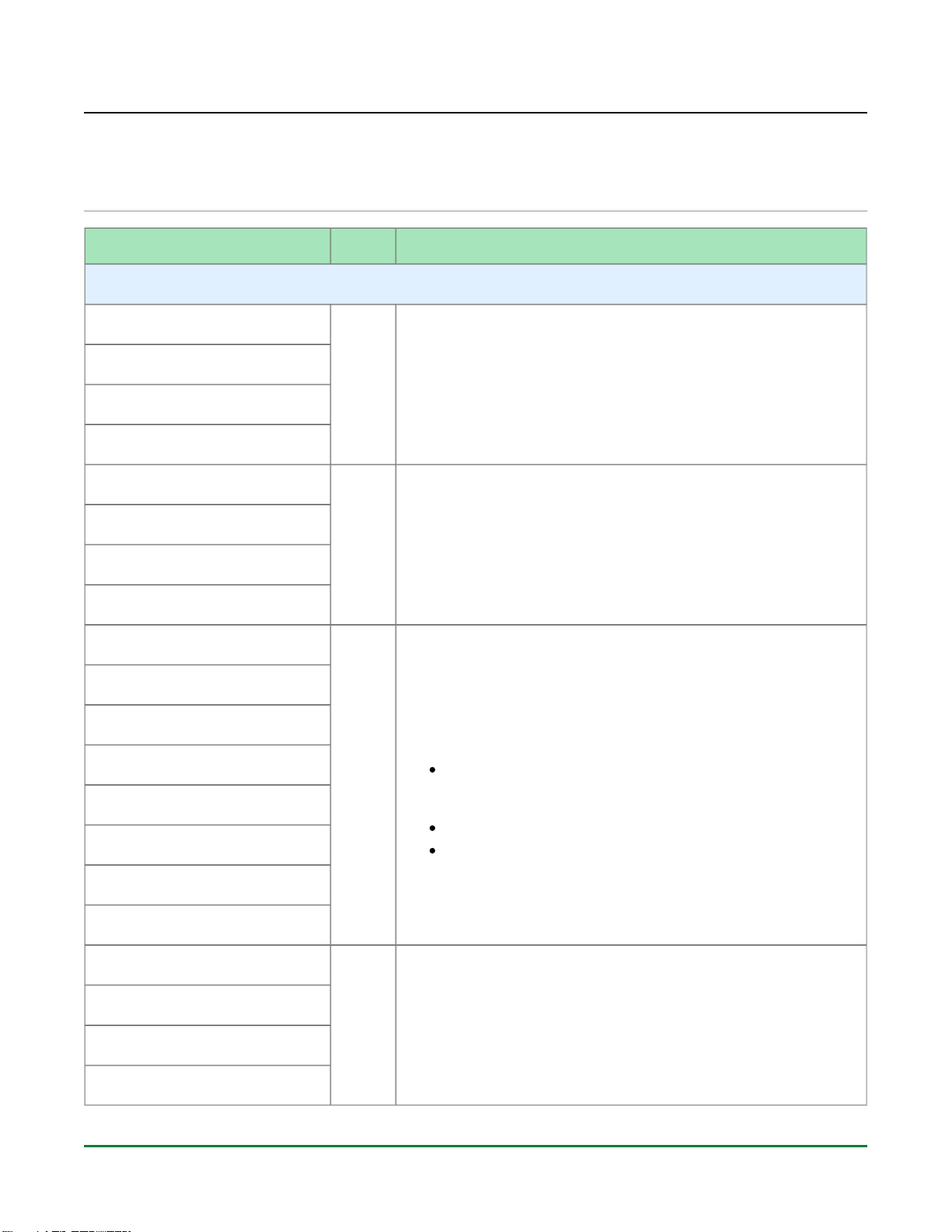
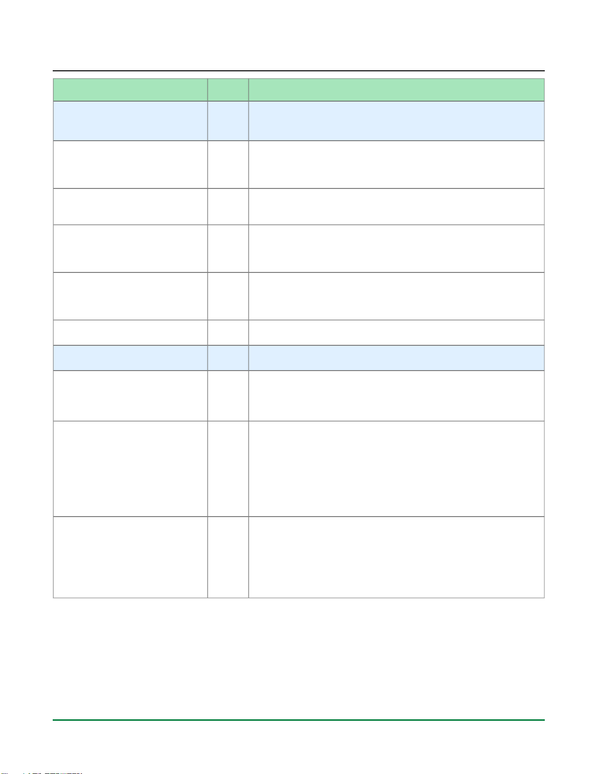
Pin Name Type Description and Connection Guidelines
FCU_STAP_SEL Input
When asserted high, this signal enables the JTAG interface pins to
be directly connected to the JTAG controller in the SerDes PMA
blocks allowing SerDes configuration, debug and performance
monitoring directly from the JTAG interface. For bitstream download
and design debug using the JTAG interface, this pin must be held
low. For SerDes PMA debug only mode, this pin must be held high.(2)
This input must be connected to a configurable input such as a DIP
switch to toggle between modes of operation for debug. If this pin is
not used then it should be tied to GND using a 10 kΩ pull-down
resistor
FCU_CONFIG_STATUS Output
Active-high configuration status output signal indicating that the FCU
has completed initial start-up and has cleared the CMEM and is
awaiting FCU commands for bitstream programming. Once high, it
stays asserted until the FCU is power cycled or reset for a re-
initialization sequence or a CRC error is seen during bitstream load.
This output is an open-drain signal. It is recommended to connect
this signal to an LED as an indicator on the board. In this case, use
an external 10 kΩ ±5% pull-up resistor to 3.0V/3.3V and drive a 1 kΩ
resistor to the input of a FET to turn on the LED. If LED usage is not
desired, this signal can be pulled-up to 1.8V (FCU_CB_VDDIO) using
the same 10 kΩ pull-up resistor.
FCU_CONFIG_SYSCLK_BYPASS Input
Active-high bypass configuration system clock setting. Along with
CFG_CLKSEL, this setting allows for clock selection during
programming (see Table: FCU Configuration Clock Selection Based
). This input should be connected to a configurable (see page 16)
input like a DIP switch to toggle between modes of operation for
debug. If this is not possible or desired, tie this off to 1.8V
(FCU_CB_VDDIO) or GND based on the desired clock for the
configuration mode.(2)
FCU_CONFIG_USER_MODE Output
Active-high output indicating that the device has transitioned into user
mode. Once high, it stays asserted until the FCU is power cycled or
reset for a re-initialization sequence. This signal is not an open drain
output, connect this pin directly to an indicator LED or configuration
controller.
FCU_CPU_CLK Input
Input clock from external CPU. The data/address bus is synchronous
to this clock. If the CPU_CLK is not used to source the FCU clock,
then pin should be tied to GND.
FCU_CPU_CSN Input
Active-low CPU mode chip select. Connect the CSN pin directly to
the configuration controller. If this pin is not used then this pin should
be pulled HIGH using a pull-up resistor.
FCU_CPU_DQ_IN_OUT[31:0] Input
/Output
Data input/output pins shared between the CPU and flash interfaces.
The CPU interface is inaccessible when the flash mode is in use and
vice-versa. If any pins are unused based on the configuration then
they should be connected to weak pull-up resistors.(3)