ACKme Networks AMW004-E02 Marlin User manual

AMW004 Evaluation
ARG-MW004E-105R •AMW004 Evaluation Guide February 27, 2015
©2014 ACKme Networks. http://ack.me
AMW004
Evaluation Guide
AMW004-E02
‘Marlin’
AMW004-E03
‘Mackerel’

AMW004 Evaluation
ARG-MW004E-105R •AMW004 Evaluation Guide Page | i Page | i
©2014 ACKme Networks. http://ack.me February 27, 2015 February 27, 2015
Disclaimer
While the information provided in this document is
believed to be accurate, it is under development and
ACKme Networks reserves the right to make changes
without further notice to the product described herein
to improve reliability, function, or design, and makes no
guarantee or warranty concerning the accuracy of said
information, nor shall it be responsible for any loss or
damage of whatever nature resulting from the use of,
or reliance upon, such information. ACKme Networks
makes no warranties of any kind, whether express,
implied or arising by custom or course of trade or
performance, and specifically disclaims the implied
warranties of title, non-infringement, merchantability,
or fitness for a particular purpose.
No part of this document may be copied, reproduced,
stored in a retrieval system, or transmitted, in any form
or by any means, electronic, mechanical, photographic,
or otherwise, or used as the basis for manufacture or
sale of any items without the prior written consent of
ACKme Networks.
Trademarks
ACKme Networks and the ACKme Networks logo are
trademarks of ACKme Networks. WICED™ is a
trademark of Broadcom® Corporation, Inc. Other
trademarks in this document belong to their respective
owners.
Copyright © 2014 ACKme Networks, Inc.
All rights reserved.
Document Number: ARG-MW004E-1xx
Release Date: February 27, 2015
Contact
http://ack.me/contact
About this User Guide
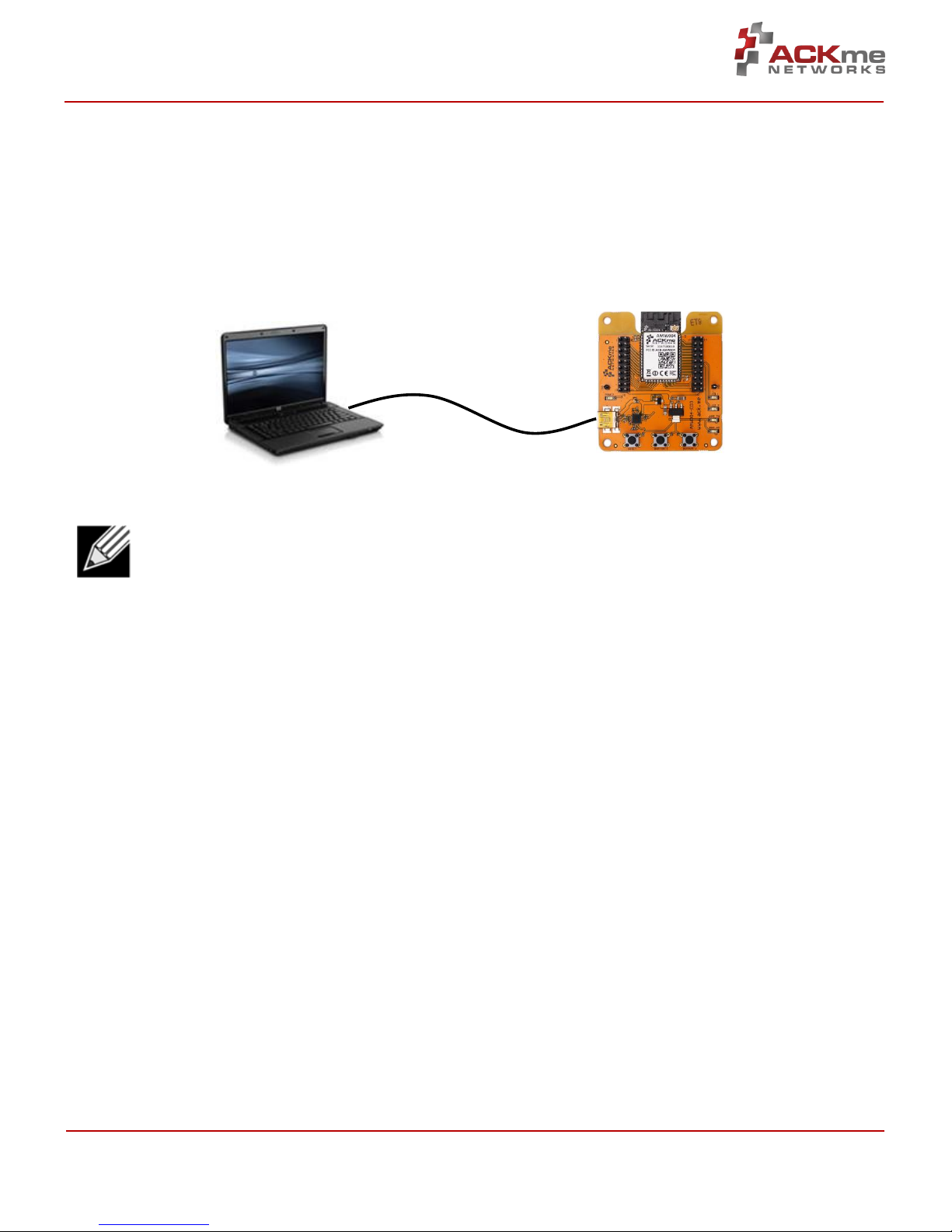
This guide provides information and basic usage
instructions for the WiConnect serial Wi-Fi application
and the AMW004 ‘Wallaby’ module available from
ACKme Networks.
Evaluation boards covered by this guide include:
AMW004-E02 ‘Marlin with Hornet’ (Revision 2)
AMW004-E03 ‘Mackerel’ (Revision 1)
Further information about WiConnect is available in the
WiConnect Reference manual online at:
http://wiconnect.ack.me
Organization
This document is organized into the following sections:
Introduction, Section 1
Feature Identification, Section 2
Using WiConnect, Section 3
Ordering Information, Section 4
Revision History & Glossary, Section 5
Appendix A –Setting up a Terminal Emulator
Appendix B –Evaluation Board Schematics

AMW004 Evaluation
ARG-MW004E-105R •AMW004 Evaluation Guide Page | ii Page | ii
©2014 ACKme Networks. http://ack.me February 27, 2015 February 27, 2015
Contents
1 Introduction ...........................................................1
2 Feature Identification ............................................2
2.1 AMW004-E02 ‘Marlin’ ....................................2
2.2 AMW004-E03 ‘Mackerel’................................4
3 Using WiConnect....................................................5
3.1 Getting Help....................................................5
3.2 System Indicator LEDs ....................................6
3.3 Scanning for Wi-Fi Networks ..........................6
3.4 Joining a Wi-Fi Network..................................6
Web Setup ..............................................6
Script Setup.............................................7
Manual Setup..........................................8
Wireless Protected Setup (WPS) ............9
3.5 Filesystem .......................................................9
3.6 UDP / TCP / TLS Clients .................................10
3.7 HTTP / HTTPS Clients ....................................11
3.8 Using GPIOs ..................................................11
3.9 Factory Reset ................................................12
3.10 Save & Reboot ..............................................12
3.11 Command vs. Stream Mode .........................13
Command Mode ...................................13
Stream Mode ........................................14
3.12 Want more?..................................................14
4 Ordering Information...........................................15
5 Revision History & Glossary .................................16
5.1 Revision History ............................................16
5.2 Glossary ........................................................16
APPENDIX A –Configuring a Terminal Application
APPENDIX B –Evaluation Board Schematics

AMW004 Evaluation
Introduction, Section 1
ARG-MW004E-105R •AMW004 Evaluation Guide Page | 1 Page | 1
©2014 ACKme Networks. http://ack.me February 27, 2015 February 27, 2015
1Introduction
The AMW004 ‘Wallaby’ module is a fully certified small form factor, low power WICED-based Wi-Fi networking
module perfectly suited to deeply embedded applications requiring medium/high data throughput in medium to
high volume.
The module runs WiConnect firmware, ACKme Networks easy-to-use and reliable serial Wi-Fi networking application
that includes an embedded TCP/IP networking stack with SSL/TLS/HTTPS security.
Evaluation of WiConnect and the AMW004 module is available with the AMW004-E02 ‘Marlin’ evaluation board, or
the AMW004-E03 ‘Mackerel’ evaluation board. The evaluation boards are shown in Figure 1 and a feature
comparison of the boards is provided in Table 1.
Figure 1. AMW004 Evaluation Boards
Table 1. AMW004 Evaluation Board Feature Comparison
Feature
AMW004-E02 ‘Marlin’
AMW004-E03 ‘Mackerel’
Product Number
AMW004-E02
(AAE001 + AMW004-A01)
AMW004-E03
Module style
Pluggable module adapter
Surface mount
Serial Interface
USB-UART
USB-UART
Power supply
from USB
from USB
User LEDs
2
2
User Buttons
2
2
Reset Button
Y
Y
Expansion Headers
2 x 10
2 x 20
Note! Customers that wish to evaluate the AMW004 module using Broadcom WICED should obtain an
alternate evaluation board that provides AMW004 program and debug capability. Information about the
AMW004-E01 ‘Snapper’ WICED eval board is available at http://ack.me/products/AMW004_E01_Snapper
AMW004-E02 ‘Marlin’
(with AMW004-A01 through-hole
module adapter)
AMW004-E03 ‘Mackerel’
(with AMW004 surface mount
module)

AMW004 Evaluation
Feature Identification, Section 2
ARG-MW004E-105R •AMW004 Evaluation Guide Page | 2 Page | 2
©2014 ACKme Networks. http://ack.me February 27, 2015 February 27, 2015
2Feature Identification
2.1 AMW004-E02 ‘Marlin’
The Marlin evaluation board assembly is in fact comprised of two separate boards that are plugged together. The
through-hole AMW004 module adapter (AMW004-A01) plugs directly into the bare evaluation board (AAE001).
Schematics for both boards are provided in Appendix B.
Figure 2. AMW004-E02 Features
Table 2. AMW004-E02 Expansion Header Connections
AMW004
Marlin V2
Marlin V3
Pin #
Pin #
AMW004
Marlin V2
Marlin V3
VDD_3V3
VDD_3V3
VDD_3V3
1
20
GPIO_28
LED_2
I2C_SDA
GPIO_14
USART1_TX
USART1_TX
2
19
GPIO_27
LED_1
I2C_SCL
GPIO_13
USART1_RX
USART1_RX
3
18
GPIO_171
GPIO_143
SPI_SCK
GPIO_191
GPIO_3
GPIO_3
4
17
GPIO_201
GPIO_13
SPI_CS
RESET_N
RESET_N
RESET_N
5
16
GPIO_15
USART1_RTS
USART1_RTS
GPIO_26
GPIO_4
BUTTON_2
6
15
GPIO_12
BUTTON_2
LED_1
GPIO_25
GPIO_5
LED_2
7
14
-2
-
-
GPIO_22
BUTTON_13
GPIO_6
8
13
GPIO_0
GPIO_10
BUTTON_1
GPIO_21
GPIO_7
THERM
9
12
GPIO_16
USART1_CTS
USART1_CTS
GND
GND
GND
10
11
GPIO_181
GPIO_8
SPI_MOSI
Notes
1Connection to AMW004 is via a 220R resistor
2Not connected to AMW004 by default. R8 must be populated with a 0R link to make the connection.
3The silkscreen is WRONG! Button 1 is actually connected to Pin 8 of the expansion header.
User LED 1
Header 2
User LED 2
USB UART Tx LED
User Button 2
User Button 1
Reset Button
Used to reset the AMW004 module ONLY
Power LED
Ground Hook
Header 1
USB Mini B Connector
Provides power to the board &
USB-Serial UART to computer
Ground Hook
USB UART Rx LED
AMW004-A01 ‘Hornet’ adaptor
,p
AMW004 Module
‘Hornet’

AMW004 Evaluation
Feature Identification, Section 2
ARG-MW004E-105R •AMW004 Evaluation Guide Page | 3 Page | 3
©2014 ACKme Networks. http://ack.me February 27, 2015 February 27, 2015
Table 3. AMW004-E02 Expansion Header Connections
AMW004
Hornet
Pin #
Pin #
AMW004
Hornet
VDD_3V3
VDD_3V3
1
20
GPIO_28
I2C0_SDA
GPIO_14
USART1_TX
2
19
GPIO_27
I2C0_SCL
GPIO_13
USART1_RX
3
18
GPIO_171
SPI_SCK
GPIO_191
SPI_MISO
4
17
GPIO_201
SPI_CS
RESET_N
RESET_N
5
16
GPIO_15
USART_RTS
GPIO_26
WAKE
6
15
GPIO_12
GPIO_12
GPIO_25
GPIO_25
7
14
-
-
GPIO_22
GPIO_22
8
13
GPIO_0
GPIO_0
GPIO_21
GPIO_21
9
12
GPIO_16
USART1_CTS
GND
GND
10
11
GPIO_181
SPI_MOSI
Notes
1Connection to AMW004 is via a 220R resistor

AMW004 Evaluation
Feature Identification, Section 2
ARG-MW004E-105R •AMW004 Evaluation Guide Page | 4 Page | 4
©2014 ACKme Networks. http://ack.me February 27, 2015 February 27, 2015
2.2 AMW004-E03 ‘Mackerel’
The Mackerel evaluation board comes complete with a surface mount AMW004 ‘Wallaby’ module. Each pin on the
Wallaby module is connected to the expansion header. Schematics for the board are provided in Appendix B.
Figure 3. AMW004-E03 Features
Table 4. AMW004-E03 Expansion Header Connections
AMW004
H1 Pin
AMW004
AMW004
H2 Pin
AMW004
VDD_3V3
1
2
GND
VDD_3V3
1
2
GND
GPIO_1
3
4
GPIO_0
GPIO_27
3
4
GPIO_28
OSC_32K_OUT
5
6
GPIO_2
GPIO_25
5
6
GPIO_26
GPIO_4
7
8
GPIO_3
GPIO_23
7
8
GPIO_24
GPIO_6
9
10
GPIO_5
GPIO_21
9
10
GPIO_22
GPIO_8
11
12
GPIO_7
GPIO_19
11
12
GPIO_20
GPIO_10
13
14
GPIO_9
GPIO_17
13
14
GPIO_18
GPIO_12
15
16
GPIO_11
USART1_CTS
15
16
USART1_RTS
RESET_N
17
18
-
USART1_TX
17
18
USART1_RX
GND
19
20
VDD_3V3
GND
19
20
VDD_3V3
Note: The H2 pin numbering shown here is for all versions after AMW004-E03.1.
In AMW004-E03.1, H2 pins were numbered in a different order, with pins 1 and 2 at the buttons end and pins 19 and
20 at the antenna end: E03.1 H2 pin 1 = E03.2+ H2 pin 19, E03.1 H2 pin 2 = E03.2+ H2 pin 20, and so on.
User LED 1
Header 2
User LED 2
USB UART Tx LED
User Button 2
User Button 1
Reset Button
Used to reset the AMW004 module ONLY
Power LED
Ground Hook
Header 1
USB Mini B Connector
Provides power to the board &
USB-Serial UART to computer
Ground Hook
USB UART Rx LED
AMW004 Module

AMW004 Evaluation
Using WiConnect, Section 3
ARG-MW004E-105R •AMW004 Evaluation Guide Page | 5 Page | 5
©2014 ACKme Networks. http://ack.me February 27, 2015 February 27, 2015
3Using WiConnect
To get started with WiConnect, plug the AMW004 evaluation board into the USB port of the computer and open a
terminal emulator as described in Appendix A. The USB cable provides the evaluation board with power and a serial
UART connection to the computer.
With the board connected to the computer, verify the power LED is illuminated. If the power LED is NOT illuminated,
try re-plugging the USB cable, or try a different USB cable.
Note! Be sure to use a quality USB cable. Inferior cables may result in reduced or intermittent operation
of the evaluation board.
3.1 Getting Help
WiConnect provides extensive help for each command and variable. To obtain a list of help options, type the help
command.
> help
The following help options are available ...
help all -> Print a list of all Commands and Variables
help commands -> Print a list of Commands
help variables -> Print a list of Variables
help <command> -> Print help for a specific Command
help <variable> -> Print help for a specific Variable
Additional help is available online at http://wiconnect.ack.me
To obtain help for a particular command or variable, type help <command> or help <variable>.
To obtain help for the wlan_scan variable, type help wlan_scan.
> help wlan_scan
Usage : wlan_scan [-v] [<channel> [ssid]]
Shortcut: scan
Brief : Initiate a Wi-Fi scan and return results; optionally specify
a channel and AP SSID to scan for. For verbose scans, -v must be the first argument
Computer with Terminal Emulator
WiConnect Evaluation Board
USB Serial

AMW004 Evaluation
Using WiConnect, Section 3
ARG-MW004E-105R •AMW004 Evaluation Guide Page | 6 Page | 6
©2014 ACKme Networks. http://ack.me February 27, 2015 February 27, 2015
3.2 System Indicator LEDs
The Mackerel evaluation board comes with three system indicator LEDs and two user LEDs. The LED functions are
configurable, using the WiConnect peripheral commands and variables. See http://wiconnect.ack.me for more
details., in particular the variables system.indicator.gpio and system.indicator.state.
By default the system indicator LEDs are configured as follows:
LED
Function
Behavior
Red
Soft AP Indicator
Off
Soft AP off
Fast blink
Soft AP error
Medium blink
Soft AP active
Slow blink
Client connected
Yellow
Network Indicator
Fast blink
No IP address
Medium blink
DHCP in progress
Slow blink
DHCP successful, IP address obtained
Green
WLAN indicator
Off
Wi-Fi off
Fast blink
Error
Medium blink
Connecting to AP
Slow blink
Joined to AP
Blink rates are as follows: Fast blink: 4Hz, Medium blink: 1Hz, Slow blink: 0.5 Hz
3.3 Scanning for Wi-Fi Networks
To scan for Wi-Fi networks in range, use the wlan_scan command. Each AP in range is listed on a separate line.
> wlan_scan -v
!3 found
! # Ch RSSI BSSID Rate Security Mode Len SSID
#00 06 -27 84:1B:5E:29:9D:F7 450.0 WPA2-Mixed Inf 17 YOUR_NETWORK_NAME
#01 11 -73 2C:B0:5D:31:6F:6A 300.0 WPA2-AES Inf 6 button
#02 11 -73 EC:1A:59:36:5B:6C 144.4 WPA2-Mixed Inf 5 REGIS
3.4 Joining a Wi-Fi Network
Several methods are available to configure and join the AMW004 module to a Wi-Fi network.
Web Setup
WiConnect provides the option to use a web browser running on a network client (such as a smartphone, tablet or
computer) to select the remote Wi-Fi network the AMW004 module should join, and to enter a password for the
remote network.
When web setup is used, it is helpful to think of the network client as the keyboard and display for the module as
shown in Figure 4.
To start web setup mode, enter the command setup web. WiConnect starts the local network and web server as
indicated by the final message: In progress.
> setup web
[Disassociated]
IPv4 address: 10.10.10.1

AMW004 Evaluation
Using WiConnect, Section 3
ARG-MW004E-105R •AMW004 Evaluation Guide Page | 7 Page | 7
©2014 ACKme Networks. http://ack.me February 27, 2015 February 27, 2015
Web setup started with the SSID: "WiConnect Web Setup"
In progress
Open the Wi-Fi settings on your smartphone, tablet or computer and join the network called Wiconnect Web
Setup. The password for the network is simply: password. The local network name and password, and the web
address may be customised to suit your needs, see the online WiConnect Reference Manual for further information.
After joining the local network, open a web browser on the network client and go to setup.com. The WiConnect web
page appears (see Figure 4), and a scan begins for Wi-Fi access points in range. Select the remote network you wish
to join, enter the network password then select Save & Exit and follow the prompts.
Once the settings are successfully saved, WiConnect prints Web Setup Mode exited to the terminal. Check that
the settings were successfully saved using get wlan.ssid and get wlan.passkey.
Web Setup Mode exited
> get wlan.ssid
YOUR_NETWORK_NAME
> get wlan.passkey
YOUR_NETWORK_PASSWORD
Figure 4. Web setup using a network client
Script Setup
If you prefer instead to enter configuration details for the Wi-Fi network, WiConnect provides a default setup script
to step you through the process. The setup script is provided as a file called default_setup.script on the
WiConnect file system. The setup script may be customised as required.
> setup cmd
> Enter Wi-Fi network name:
set wlan.ssid YOUR_NETWORK_NAME
Set OK
> Enter Wi-Fi network password:
set wlan.passkey YOUR_NETWORK_PASSWORD
Set OK
>
Remote Network
Name: YOUR_NETWORK_NAME
Local Network
Name: WiConnect Web Setup
Password: password

AMW004 Evaluation
Using WiConnect, Section 3
ARG-MW004E-105R •AMW004 Evaluation Guide Page | 8 Page | 8
©2014 ACKme Networks. http://ack.me February 27, 2015 February 27, 2015
set wlan.auto_join.enabled true
Set OK
> Saving settings
save
Saved
Success
>
network_up
[2014-05-17 | 11:48:31: Associating to YOUR_NETWORK_NAME]
In progress
> Security type from probe: WPA2-Mixed
Obtaining IPv4 address via DHCP
IPv4 address: 192.168.0.31
[2014-05-17 | 11:48:41: Associated]
> Exiting Cmd Setup Mode
Manual Setup
The network_up command has a –s option (scan) to simplify setup. It outputs a numbered list of available
networks and prompts for a selection, the prompts for the passkey.
> network_up -s
Scanning for networks...
! 3 networks found
! # Ch RSSI MAC (BSSID) Network (SSID)
# 0 6 -27 84:1B:5E:29:9D:F7 Take the blue pill
# 1 11 -68 EC:1A:59:36:5B:6C button_xt
# 2 11 -70 2C:B0:5D:31:6F:6A button
Type the number # that matches your Network: 0
Type the password for your Network : welcome-to-kansas
[Associating to Take the blue pill]
In progress
[Associated]
This procedure automatically sets the wlan.ssid and wlan.passkey values. Save after running network_up –s to
preserve the values through reset.
Alternatively, it is straight forward to manually enter the name and password for the network using the wlan.ssid
and wlan.passkey variables. Be sure to save afterwards, or the values will be lost when the module reboots. Any
subsequent command requiring network access, such as an ICMP (Internet Control Message Protocol) ping,
automatically results in the module attempting to join the network.

AMW004 Evaluation
Using WiConnect, Section 3
ARG-MW004E-105R •AMW004 Evaluation Guide Page | 9 Page | 9
©2014 ACKme Networks. http://ack.me February 27, 2015 February 27, 2015
> set wlan.ssid YOUR_NETWORK_NAME
Set OK
> set wlan.passkey YOUR_NETWORK_PASSWORD
Set OK
> save
Saved
Success
> ping -g
[Associating to YOUR_NETWORK_NAME]
Security type from probe: WPA2-Mixed
Obtaining IPv4 address via DHCP
IPv4 address: 192.168.0.31
[Associated]
Ping reply in 25ms
Wireless Protected Setup (WPS)
WPS is a Wi-Fi provisioning method originally intended to simplify the process of connecting Wi-Fi clients to Wi-Fi
Access Points. WPS offers both a push-button and PIN entry method for configuration. In reality, WPS push-button
(as opposed to PIN) is the only method that has gained some level of adoption in the industry, however WPS
naturally only works when the Wi-Fi AP supports WPS.
Many AP vendors choose not to test and certify APs with the Wi-Fi Alliance, and the lack of a standard WPS logo next
to the WPS button on an AP often means many users are unaware that WPS is available. The potential for equipment
incompatibility and added user confusion mean it is unwise to rely on WPS as the primary method of Wi-Fi
provisioning in the real world.
Incompatibility and confusion aside, WiConnect provides full support for WPS1.0 & WPS2.0 and the underlying WPS
engine has passed Wi-Fi certification. To use WPS in push-button mode, simply enter the wps command into
WiConnect, then press the WPS button on your router (if the router supports WPS, and it is enabled, and you can
find the button), and wait for the magic to happen.
3.5 Filesystem
ACKme Wi-Fi modules running WiConnect include a serial flash memory and a filesystem that provides users with the
ability to read and write files. A quick example showing how to create, manipulate then delete a file is provided
below.
> file_create hello.txt 13
my hello data
File created
Success
> ls
! # Size Version Filename
# 0 1853 1.2.0 /favicon.ico.gz
# 1 18067 1.2.0 /setup/images.png
# 2 10525 1.2.0 /setup/index.css.gz
# 3 10134 1.2.0 /setup/index.html
# 4 39114 1.2.0 /setup/index.js.gz
# 5 32251 1.2.0 command_help.csv
# 6 130 1.2.0 default_setup.script
# 7 1236 1.2.0 geotrust_ca.pem
# 8 13 1.0.0 hello.txt
# 9 352516 1.2.0 upgrade_app.exe
# 10 109600 1.2.0 wiconnect.exe
# 11 191677 1.2.0 wifi_fw.bin

AMW004 Evaluation
Using WiConnect, Section 3
ARG-MW004E-105R •AMW004 Evaluation Guide Page | 10 Page | 10
©2014 ACKme Networks. http://ack.me February 27, 2015 February 27, 2015
> file_open hello.txt
[Opened: 0]
0
> stream_read 0 5
my he
> stream_read 0 50
llo data
[Closed: 0]
> file_delete hello.txt
File deleted
Success
>
Note! When reading the contents of a file using stream_read, the file is automatically closed if the end of
file is reached.
3.6 UDP / TCP / TLS Clients
To open a UDP, TCP or secure TLS connection to a remote server, use the udp_client, tcp_client or
tls_client commands. WiConnect responds with a stream handle if the connection is opened successfully. For TLS
connections, WiConnect provides a default TLS root certificate signed by GeoTrust (located on the WiConnect file
system), however this certificate may not work with some TLS servers. A custom certificate may be provided as an
option to the tls_client command if required.
> udp_client test.ack.me 50019
[Opening: test.ack.me:50019]
Resolving host: test.ack.me
Connecting: 107.170.222.80:50019
[2014-05-19 | 11:12:22: Opened: 0]
0
> tcp_client test.ack.me 50019
Resolving host: test.ack.me
[2014-05-19 | 11:12:38: Opening: test.ack.me:50019]
Connecting (TCP): 107.170.222.80:50019
[2014-05-19 | 11:12:39: Opened: 1]
1
> tls_client google.com 443
Resolving host: google.com
[2014-05-19 | 11:12:49: Opening: google.com:443]
Connecting (TLS): 74.125.237.174:443
[2014-05-19 | 11:12:50: Opened: 2]
2
Now try writing a character to the UDP or TCP stream that was opened in the examples above (remember,
WiConnect does NOT echo characters typed after the stream_write command). The server at http://test.ack.me
responds with a character pattern using the Chargen (Character Generator) protocol.
> stream_write 0 1
Success
> stream_read 0 50
!"#$%&'()*+,-./0123456789:;<=>?@ABCDEFGHIJKLMNOPQR
Note! WiConnect supports TCP server mode too!
For more information, please refer to the WiConnect Reference Guide.

AMW004 Evaluation
Using WiConnect, Section 3
ARG-MW004E-105R •AMW004 Evaluation Guide Page | 11 Page | 11
©2014 ACKme Networks. http://ack.me February 27, 2015 February 27, 2015
3.7 HTTP / HTTPS Clients
To open an HTTP or secure HTTPS connection to a remote server, read the first 300 bytes of the response then close
the connection, use the http_get, stream_read and stream_close commands. WiConnect responds with a
stream handle if the connection is opened successfully.
> http_get https://www.google.com
[2014-05-19 | 11:14:31: Opening: https://www.google.com]
Request GET /
Connecting (HTTP): www.google.com:443
Starting TLS
[2014-05-19 | 11:14:31: Opened: 0]
HTTP response: 302
Redirected to https://www.google.com.au/?gfe_rd=cr&ei=l-d5U9m2J6GN8QfexoHYCg
Request GET /?gfe_rd=cr&ei=l-d5U9m2J6GN8QfexoHYCg
Connecting (HTTP): www.google.com.au:443
Starting TLS
HTTP response: 200
Status: 200
0
> stream_read 0 300
<!doctype html><html itemscope="" itemtype="http://schema.org/WebPage" lang="en-
AU"><head><meta content="/images/google_favicon_128.png"
itemprop="image"><title>Google</title><script>(function(){
window.google={kEI:"mOd5U4eZAYTVkAXF2oDwBA",getEI:function(a){for(var
b;a&&(!a.getAttribute||!(b=a.getAt
> stream_close 0
[2014-05-19 | 11:14:47: Closed: 0]
Success
>
3.8 Using GPIOs
In WiConnect, a GPIO may have two functions: a standard IO function or an alternate function (such as a system
indicator, status GPIO or control GPIO). When a GPIO is configured with an alternate function, the standard IO
function is NOT available and the gpio_dir, gpio_set, and gpio_get commands are disabled for that GPIO.
Before a GPIO can be used, it is necessary to first check whether the GPIO is being used for an alternate function, or
is already in use as a standard GPIO (for another purpose). If the GPIO is in use, it must first be freed up by setting
the direction of the GPIO to none using the gpio_dir command (standard IO) or by disabling the alternate function.
The example below demonstrates how to control GPIO 26 on the AMW004 module. GPIO 26 is unassigned GPIO
after factory reset.

AMW004 Evaluation
Using WiConnect, Section 3
ARG-MW004E-105R •AMW004 Evaluation Guide Page | 12 Page | 12
©2014 ACKme Networks. http://ack.me February 27, 2015 February 27, 2015
On AMW004-E02 (Marlin): Header Pin 6 = AMW004 GPIO 26
On AMW004-E03 (Mackerel): Header 2 Pin 6 = AMW004 GPIO 26
> gpio_dir 26 out
Set OK
> get gpio.usage
! # Description
#13 - UART1 RX
#14 - UART1 TX
#17 - SPI CLK
#18 - SPI MOSI
#19 - SPI MISO
#21 - system.indicator.network
#22 - system.indicator.wlan
#26 - Standard I/O
> gpio_set 26 0
Set OK
> gpio_set 26 1
Set OK
> gpio_set 26 0
Set OK
3.9 Factory Reset
The AMW004 module may be factory reset using the factory_reset command or by holding the factory reset pin
(GPIO 0 on all ACKme modules) high for more than 10 seconds through a hardware reset. After a successful factory
reset, all variables are set to factory defaults and the module reboots. To avoid accidental factory reset, the Wi-Fi
MAC address must be provided when calling the factory_reset command.
> get wlan.mac
4C:55:DC:15:02:5D
> factory_reset 4C:55:DC:15:02:5D
Reverting to factory default settings
Setting boot app to wiconnect.exe (0)
wiconnect-1.1.0.5, Built:2014-05-07 00:07:31 for AMW004.3, Board:AMW004-E03.1
[Ready]
>
3.10 Save & Reboot
When the value of a WiConnect variable is changed, the new value is only saved to RAM (not flash!). The value of
unsaved variables is lost when the module is reset or rebooted. To save variables to non-volatile flash memory, use
the save command. The following example demonstrates that failing to save the wlan.ssid prior to reboot results
in the newly assigned value being lost.
> set wlan.ssid ssid_WONT_be_saved
Set OK
> reboot
[Disassociated]
Rebooting
wiconnect-1.1.0.5, Built:2014-05-07 00:07:31 for AMW004.3, Board:AMW004-E03.1
[Ready]
> get wlan.ssid
> set wlan.ssid ssid_WILL_be_saved
Set OK
> save
Saved

AMW004 Evaluation
Using WiConnect, Section 3
ARG-MW004E-105R •AMW004 Evaluation Guide Page | 13 Page | 13
©2014 ACKme Networks. http://ack.me February 27, 2015 February 27, 2015
Success
> reboot
[Disassociated]
Rebooting
wiconnect-1.1.0.5, Built:2014-05-07 00:07:31 for AMW004.3, Board:AMW004-E03.1
[Ready]
> get wlan.ssid
ssid_WILL_be_saved
>
Note! WiConnect configures some services (such as GPIO initialization) only after reboot. It may be
necessary to save and reboot the module before the new value of some variables takes effect.
3.11 Command vs. Stream Mode
The WiConnect serial interface may be used in either Command Mode or Stream Mode. A brief description of each of
these modes is provided in the following text. For detailed information, please refer to the WiConnect Reference
Guide.
Command Mode
Command mode provides an asynchronous command interface that a host may use to send and receive control and
data information. Command mode is typically used by a host to configure WiConnect, however it may also be used
by simple hosts that need ultimate master/slave control over information sent to, and received from, the module. All
preceding examples demonstrate usage of WiConnect in command mode.
There are two ways to interact with WiConnect in Command mode. When operating in human friendly command
mode, WiConnect provides verbose asynchronous responses that are easy for humans to read. In machine friendly
command mode, verbose prints and the command prompt are disabled and a well-defined response header is
returned after each command.
Configuring Command Mode
Command mode can be configured using the convenience variable system.cmd.mode
Command
Description
set system.cmd.mode human
Enable human friendly command mode
set system.cmd.mode machine
Enable machine friendly command mode
Setting system.cmd.mode executes a macro that sets the value of the four variables used to switch between
human and command mode. These variables, together with the human and machine mode setting, are listed in the
following table.
Command
Human
/
Machine
Description
set system.print_level
all
/
0
Set debug & informational print level
set system.cmd.header_enabled
0
/
1
Disable/enable a response header
set system.cmd.prompt_enabled
1
/
0
Turn on/off the user prompt
set system.cmd.echo
on
/
off
Turn on/off character echo. In human
mode, lets you see what you're typing

AMW004 Evaluation
Using WiConnect, Section 3
ARG-MW004E-105R •AMW004 Evaluation Guide Page | 14 Page | 14
©2014 ACKme Networks. http://ack.me February 27, 2015 February 27, 2015
Stream Mode
Stream Mode provides a streaming interface that transparently connects a WiConnect serial interface with a network
stream such as a UDP, TCP or TLS client or server. Stream mode provides a simple 1-1 connection between a physical
serial interface and a network stream.
Bytes or characters sent from the host to a serial interface are transparently pushed by WiConnect to a network
stream via a wireless interface. Conversely, bytes or characters received by a network stream (from a remote server)
via a wireless interface are transparently pushed by WiConnect to a serial interface connected to the host. A wireless
serial port is a typical application that uses stream mode.
3.12 Want more?
The WiConnect Reference Guide, available online at http://wiconnect.ack.me, provides detailed information about
all WiConnect features, commands and variables, versions and release notes.
A number of simple and more sophisticated example applications are also provided to help you get the most out of
WiConnect and the AMW004 module.

AMW004 Evaluation
Ordering Information, Section 4
ARG-MW004E-105R •AMW004 Evaluation Guide Page | 15 Page | 15
©2014 ACKme Networks. http://ack.me February 27, 2015 February 27, 2015
4Ordering Information
Table 4 provides ordering information for AMW004 evaluation boards.
Table 5. Ordering Information
Part Number
Picture
Description
AMW004-A01
‘Hornet’
Hornet module adapter. Includes AMW004 module.
AAE001
Bare bones evaluation board that takes an AMW004-A01 Hornet module
adapter.
Does NOT include a AMW004-A01 ‘Hornet’module adapter!
AMW004-E02
‘Marlin’
WiConnect development and evaluation platform for the AMW004-A01
Hornet through-hole pluggable module adapter. This part number
includes both the AAE001 evaluation board and the AMW004-A01
module.
AMW004-E03
‘Mackerel’
WiConnect development and evaluation platform for the surface-mount
AMW004 module. This board is similar to the AAE001 Marlin board but is
instead fitted with a surface mount AMW004 module that is not
removable.

AMW004 Evaluation
Revision History & Glossary, Section 5
ARG-MW004E-105R •AMW004 Evaluation Guide Page | 16 Page | 16
©2014 ACKme Networks. http://ack.me February 27, 2015 February 27, 2015
5Revision History & Glossary
5.1 Revision History
Table 6: Document Revision History
Revision
Date
Change Description
ARG-MW004E-100R
May 18, 2014
First release
ARG-MW004E-101R
May 20, 2014
Added a section on USB Serial driver verification
ARG-MW004E-102R
August, 2014
Added AMW004-A01 ‘Hornet’ mechanical dimensions
Updates for WiConnect 1.2 release
ARG-MW004E-103R
October 22, 2014
Correct Mackerel H2 pin numbering error, update manual setup,
update Configuring a Terminal with Windows driver procedure.
ARG-MW004-104R
November 21, 2014
Add System Indicator LEDs section
5.2 Glossary
In most cases, acronyms and abbreviations are defined on first use. A comprehensive list of acronyms and other
terms used in ACKme Networks documents are provided on the ACKme Networks website at
http://ack.me/FAQs/Glossary.

AMW004 Evaluation
Appendix A –Configuring a Terminal Emulator
ARG-MW004E-105R •AMW004 Evaluation Guide Page | 17 Page | 17
©2014 ACKme Networks. http://ack.me February 27, 2015 February 27, 2015
APPENDIX A –Configuring a Terminal Application
The following instructions describe how to obtain and install a serial terminal application for use on computers
running a Windows® or OS X operations system. ACKme recommends using PuTTY for Windows® systems and
CoolTerm for OS X systems, however other equivalent applications may work equally well.
Plug the evaluation board into the computer using a USB cable before continuing.
Verify USB-Serial Driver Installation
The USB-Serial interface on WiConnect evaluation boards is based on an FTDI chip used widely in the industry. Most
operating systems including Windows®, OS X, and Linux provide integrated FTDI driver support as part of the
operating system. However some older machines, or machines that do not pickup regular updates, the driver may
not automatically install and it is necessary to manually install the driver.
On computers running Windows®, check if the driver is installed as follows:
Display the System Control Panel (e.g. press the ‘Windows’ key + Pause key).
In the left-hand column near the top of the panel, click Device Manager
In the Device Manager dialog, expand the Ports (COM and LPT) branch
FTDI drivers appear under the USB Serial Port items. If no items of this kind appear, the drivers may
not be installed.
Note: The driver entry may not appear if the ACKme device is not connected to the USB port and
powered on.
Double click the USB Serial Port entry.
Select the General tab in the USB Serial Port Properties dialog. Check the following:
oManufacturer: FTDI
oDevice status: This device is working properly
Select the Driver tab in the USB Serial Port Properties dialog. Check the following:
oDriver Provider: FTDI
oUpdate drivers if necessary by clicking the Update Driver… button.
In some cases, the FTDI driver may actually be correctly installed, but the driver may not enumerate
as a Virtual Communications Port (VCP). If this is the case, find the device under the USB Serial Bus
controllers section of the Device manager, open the device, check the VCP box, then click OK. It may
be necessary to unplug/replug your evaluation board in order for the VCP driver to load correctly.
If the FTDI drivers do not appear to be installed, see the installation instructions on the FTDI official site:
http://www.ftdichip.com/Support/Documents/InstallGuides.htm
This manual suits for next models
1
Table of contents
Other ACKme Networks Motherboard manuals