ACME A2033T FLASH User manual

1/10 Scale 2WD EP Desert Buggy
THIS R AD IO C ON TR OL LE D RA CI NG C AR I S NO T A TO Y!
TH IS H IG H- PE RF OR MA NC E R/ C MO DE L IS R EC OM ME ND ED F OR A GE S 14 A ND O LD ER .
TH IS I S ON LY F OR Y OU R RE FE RE NC E BE FO RE Y OU O PE RA TE T HE M OD EL C AR .
PL S DO N OT C HA NG E TH E EQ UI PM EN T OF E SC , MO TO R AN D BA TT ER Y CA SU AL LY , WE LL , WE H AV E
AT TA CH ED S EV ER AL E QU IP ME NT S, P LE AS E RE FE R TO T HE D ET AI LE D PA RT S LI ST . WE W IL L NO T
TA KE A NY C HA RG E OF T HE D AM AG ES O R IN JU RI ES C AU SE D BY Y OU R CH AN GE S!
AS SE MB LE TH IS K IT O NL Y IN P LA CE S OU T OF C HI LD RE N'S R EA CH !
TA KE E NO UG H SA FE TY P RE CA UT IO NS P RI OR T O OP ER AT IN G TH IS M OD EL .Y OU A RE
RESPONSIBLE FO R TH IS MODEL'S A SS EM BL E AND SA FE OPERATION!
A2033T FLASH
V1 for Brushed version ; V2 for Brushless version

BEFORE YOU RUN YOUR CAR
Required equipement for operationRequired equipement for operation
1. Tools required for building and maintenance:
Hobby knife Precision ruler or caliper
Needle nose pliers
Hobby scissors Philips screwdriver
Hex wrench
Wire cutters
Thread locking compound Cross wrench
CA glue & rubber cement
IMPORTANT!!!
Check all the screws are tight before using the car!
Check all the screws are still tight after every battery
pack used in the car!
RECOMMENDED:
Use thread lock on all scews that work loose.
PLEASE READ BEFORE STARTING!
Thank you for selecting our racing product ! This vehicle is designed to be fun to drive and uses
good quality parts for durability and performance. The instruction manual you are reading was
designed to be easy to follow yet thorough in its explanations. We want you to enjoy driving your
new R/C car. Well, before you throw down this manual and unleash your new vehicle, please
continue reading for just a few short minutes.
SAFETY GUIDELINES
The vehicle is not intended for use by children without direct supervision of a responsible, know-
ledgeable adult. We shall not be liable for any loss or damages, whether direct or indirect
C A
-1-

special, incidental, or consequential, arising from the use, misuse, or abuse of
this product and/or
any product or accessory required to operate this product.
special, incidental, or consequential, arising from the use, misuse, or abuse of this product and/or
any product or accessory required to operate this product.
IMPORTANT POINTS TO REMEMBER:
Always, turn on your transmitter first before turning on your vehicle receiver switch. When turning an
R/C vehicle off, the order is just the opposite: Turn the receiver switch off first and then turn the trans-
mitter off. Just remember that when your vehicle is turned ON, your transmitter should always be turned
ON. If not, your vehicle will no longer be under the control of your transmitter, and could unexpectedly
take off on its own, causing damage to itself and other people.
Never use old, worn out batteries in your transmitter or vehicle. Use only fresh batteries or fully charged
rechargeable batteries to ensure that you will not exceed the range of your radio system while driving
your vehicle. It is also very important to stop your vehicle immediately when you begin to see that it is
slowing down. This means the batteries in your vehicle are close to being fully discharged, and if you
continue to run your vehicle after it has slowed, it may run "out of control" since it does not have suffi-
cient voltage left to receive the signals from your transmitter.
Only run your vehicle in safe, open areas that will not put anything or anyone in danger of a collision.
Use common sense when driving your vehicle to ensure that you are not causing a potential hazard
to anyone(crowds of people and confined areas should be avoided). Although the model is small
and light weight, it can still hurt when it runs into your ankle height. It can also startle someone who
is not expecting it, so it is extremely important to ALWAYS keep a safe distance between any people
and the path of your vehicle(don't forget this includes yourself)!
Never run your vehicle through puddles, wet grass, snow or any other type of moisture. Also never
use any liquid cleaners around the electronic components on your vehicle. Any small amount of
moisture can cause severe damage to your electronics.
If you be running your vehicle with other R/C vehicles, always confirm before turning your transmitter
on, that no one else is using your same frequency channel. If neccessary, you may change fre-
quencies(certainly this is not related to 2.4G use).
Always let your motor and battery cool down completely between
runs. The motor needs to cool completely at the end of a charge
before using again. Heat is a big enemy of electric motors.
Overheating the motor will shorten its life and can cause it to fail.
Prolonged running on high drag surfaces like grass, carpet etc.
can heat the motor up and cause possible failure.
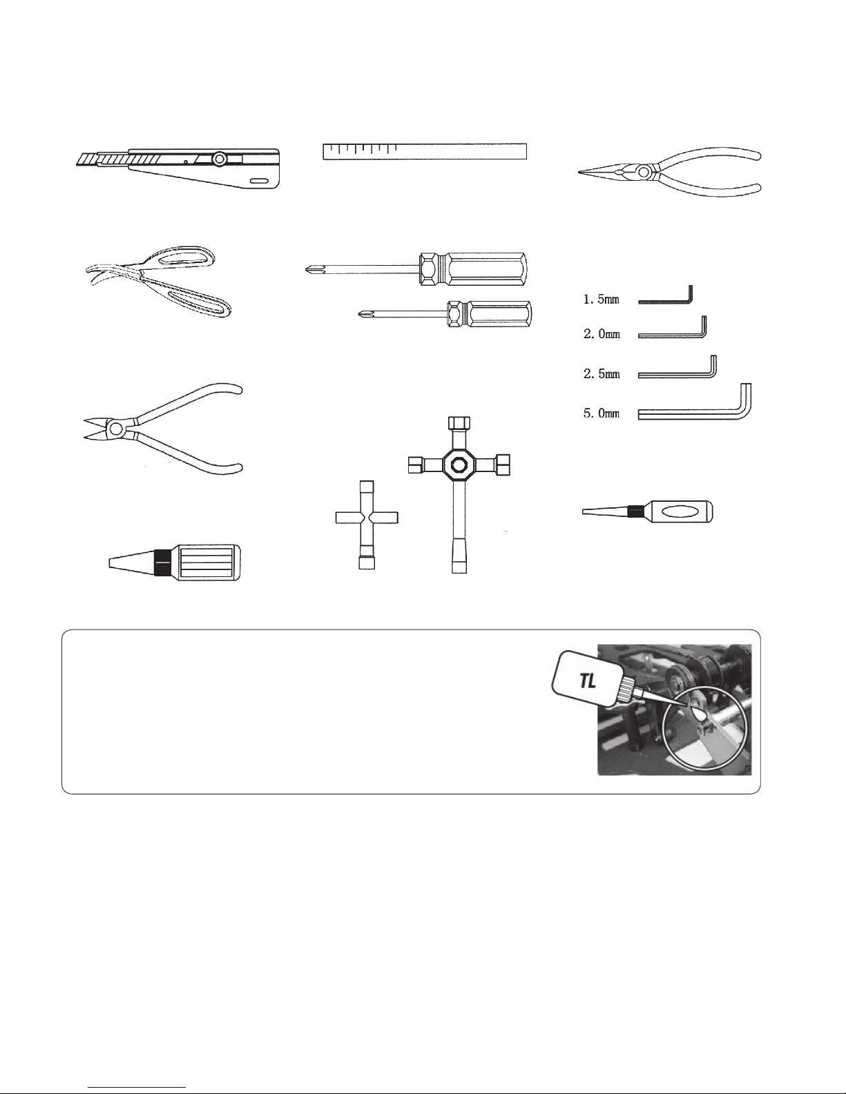
WHAT ELSE IS NEEDED
8 "AA" alkaline batteries(for the radio transmitter)
GETTING STARTED
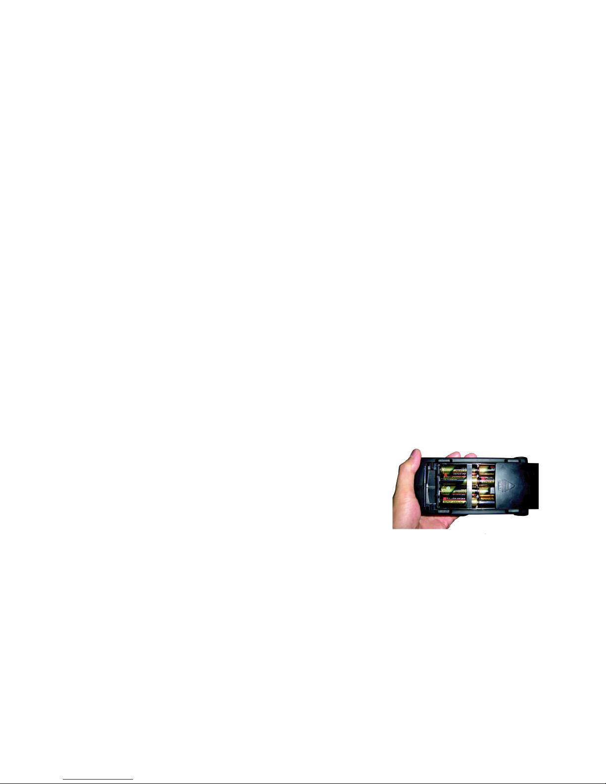
1. INSTALLING TRANSMITTER BATTERIES
Install 8 new "AA" batteries into your vehicle transmitter.
Check the life and proper installation of your batteries by switching the transmitter to ON. On vehicle
transmitters, you should see all three LED'S light up(Red, yellow, and green). If you do not, your
batteries may be low on voltage or you may not have installed them all correctly.
As the life of your transmitter batteries begins to decline, the green LED will no longer light. When you
notice that you are down to only the yellow and red lights, this is a caution sign that it is time to install
new batteries. If you continue operating your vehicle, and see that the yellow light goes out(and only
the red light is lit), STOP IMMEDIATELY! Your vehicle may easily travel out of range causing you to
lose all control, which could result in a collision causing damage to the vehicle or other property.
-2-

H
G
F
A
B
D
C
E
I
J
-3-
2. CHARGING YOUR VEHICLE
Charge your vehicle's battery pack. Connect the charger in the box to your battery pack(it will only plug in
one direction) and then plug the charger into a standard wall outlet. Charging takes approximately 2-3
hours. When the battery is fully charged, unplug the charger and connect the battery to your speed
control.
Your vehicle charger will safely charge your battery pack and not over charge it. Be careful when using
after market chargers that you do not overcharge the battery pack and ruin it.
By the way, this charger is only for the vehicle, not for the radio control.
3. ASSEMBLING THE ANTENNA
Locate the plastic antenna tube(found inside the manual bag).
Run the antenna wire up through the rear antenna mount hole in the
upper chassis plate and begin feeding it into the plastic antenna tube
until it comes out the other side. Pull the remaining wire through the
tube, and then press the tube into the antenna mount in the upper
chassis plate. Bend the antenna wire down around the tube and
install the black rubber antenna cap on the top of the tube. You
may then wrap the remaining wire arount the tube.
DO NOT cut the antenna wire off! This could shorten the range of
your radio system.
4. LEARNING THE TRANSMITTER - AM(Brushed version use)
Before turning on your vehicle, please familiarize yourself with the controls and adjustments of the radio
transmitter.
You may use the following diagram to confirm the location and function of each of these features.
A. ON/OFF Switch: Controls power to the transmitter.
B. Steering Wheel: Steering the vehicle left and right.
C. Throttle Trigger: Contols the speed and the Forward/Reverse
direction of the vehicle.
D. Throttle Trim: Ajusts the neutral position of the throttle so
your vehicle responds correctly to the trigger.
E. Steering Trim: Adjusts the neutral position of the throttle so
your vehicle travels straight.
F. Throttle Reverse Switch: Reverses the forward/reverse direction
of the steering wheel.
G. Steering Reverse Switch: Reverse the left/right direction of
steering wheel.
H. Antenna: Transmits radio signals to your receiver.
I. Recharging Jack: you can charge the battery with your charger
if you are using rechargeable batteries in your transmitter.
Caution: You can not recharge Non-rechargeable batteries.
J. Battery Power Indicators: Signal when it is time to replace your
transmitter batteries when the red indicator lit up.
L. Frequency Crystal: Controls the operating frequency(channel) of your transmitter.

-4-
L
5. To change frequency crystals simply remove the black plastic crystal
holder from the back of your transmitter by carefully pulling it straight
out. Slide the crystal out of the holder and install the new crystal labeled
“ Tx”in its place. Then carefully align the two pins that extend from
the transmitter, and gently press it into place.
Do not force the crystal! The pins can easily be broken! Remove the
crystal from your receiver in the same careful manner using a pair of
needle-nose pliers and install the new “Rx”crystal in its place.
PLEASE NOTE:
It is very important that the crystal labeled “ Tx” is installed in the
transmitter and the crystal marked “ Rx”is installed in the receiver.
RUNNING MULTIPLE VEHICLE(related to AM FM transmitter use)
If you have some vehicles that would like to get a vehicle of their own or already have friends with
other vehicles that you will be racing, it is very important that you first check what frequency channe
your vehicle is on and confirm that none of your friends have the same frequency as yours. If you do
find that someone else is using the same frequency channel that you are, you must wait for them to
turn their transmitter and vehicle OFF or you may choose to change the frequency crystals in your
transmitter and receiver (so that you can run together at the same time without causing any radio
interference). Additional frequency cystal sets can be purchased separately and installed in a few
quick seconds.
While if you have our optional radio control system- 2.4G at hand, please read as following:
LEARNING THE OPTIONAL TRANSMITTER - 2.4G
You may use the following diagram to confirm the location and function of each of these features.
A. ON/OFF Switch: Controls power to the transmitter.
B. Steering Wheel: Steering the vehicle left and right.
C. Throttle Trigger: Contols the speed and the Forward/Reverse
direction of the vehicle.
D. Throttle Trim: Ajusts the neutral position of the throttle so
your vehicle responds correctly to the trigger.
E. Steering Trim: Adjusts the neutral position of the throttle so
your vehicle travels straight.
F. Throttle Reverse Switch: Reverses the forward/reverse direction
of the steering wheel.
G. Steering Reverse Switch: Reverse the left/right direction of
steering wheel.
H. Antenna: Transmits radio signals to your receiver.
I. Recharging Jack: you can charge the battery with your charger
if you are using rechargeable batteries in your transmitter.
Caution: You can not recharge Non-rechargeable batteries.
J. Battery Power Indicators: Signal when it is time to replace your
transmitter batteries when the red indicator lit.
K. Steering Knob: Adjusts the steering angle
L. Start button: Channel 3.

-5-
2.4GHZ Frequency Pin Setup
1. Switch on the transmitter.
2. Turn on the receiver power(you can choose any channel), plug the jumper into”BIND/BATT” stop of
receiver. When the indicator starts flashing, that means the receiver comes into the set code mode.
At this point, pull out the jumper immediately.
3. The receiver can automatically find the nearest transmitter to match with. Once they match successfully,
the indicator would keep lighting(at this moment, please plug the jumper into” BIND/BATT” again.)
And if the indicator flashes continuously, that means they haven’t matched successfully, please re-try.
6. LET THE FUN BEGIN!
After reading all of the above information, you are likely ready to
start racing!
Just proceed as follows:
A. Fully extend the antenna on your transmitter.
B. Turn your transmitter on.
C. Turn your vehicle on.
D. Adjust the “ThrottleTrim” knob on your transmitter if necessary(if the wheels are moving forward
without touching the trigger, turn the throttle trim counter clockwise untill the wheels stop.)
PLEASE NOTE:
If you do not have any “reverse” when pusing the trigger forward twice , adjust the throttle trim further in
the counter clockwise direction. If you pull the trigger all the way back to forward full speed and your car
stops, then adjust the throttle trim in the clockwise direction. But becareful not to go too far or your
vehicle may not be able to reach full speed when pulling the trigger all the way back.
E. Adjust the “Steering Trim” knob on your transmitter if necessary (so your car will travel in a straigth
line without turning the steering wheel)
F. By now you are likely kicking up dust or burning up the asphalt. We highly recommend that you
continue readding the reminder of this manual to find out how you can get even more enjoyment
out of your vehicle.

Instructions of Brushed ESC B1006
【FEATURES】
This ESC is set up in a simple way for easy operation. When switched on, it automatically searches the
neutral point. When the automatic setup is finished, the motor sends out “DO” “RE” “ME” music, indicating
it snatches the neutral point. It’s easy to operate.
【SPECIFICATIONS】
Input: 6V-8.4V DC
● BEC: 5V 1A
● Current Drain: 20A(forward), Max(spark): 300A; 150A(back, spark)
● Size: 35mm(L) * 33mm(W) * 30mm(H), Weight: 48.2g
● Applicable: 540/50T motor and above.
Wire diagram:
Setup:
Connect all wires according to the diaram, then switch on the radio.(Put to default setting for Programmable
radio.) Switch on the power of the ESC, and you’ll hear “DO, RE, MI” music. The music indicates that the
transmission is on, and the neutral point is set up. If the motor does not stop running a short while after the
neutral point is set, please switch off the ESC and then switch it on again to get the neutral point.
Functions: Warning:
Forward: push the throttle on the radio(for gun-type radio, This ESC is not water-proof, Water
trigger the throttle), the car goes forward; should be avoided. If water goes
into it, take down the power switch,
Brake: put the throttle to REVERSE to brake the car; and use a blower to dry the ESC at
meduim temperature, then test it
Reverse: put the throttle to REVERSE when the car is not running, again.
the car will run backward. Backward speed can be proportion ally
controlled by adjusting the throttle. During backward running, when It’s dangerous to touch the motor
the throttle is pushed forward, the motor will run reversely. This will after running, as it emits heat during
brake the car temporally. running, and the cooling plate is hot
after running.
LED indicator is always on during forward, reverse and brake mode.
When the ESC is not working and the car stops, LED indicator is off;
When the radio is switched off, LED indicator on the ESC flashes.
-6-
●

-7-
Instructions of Brushless ESC B1112
【FEATURES】
● Compatible with all sensorless brushless motors.
● With 3 running modes-Forward with Brake, Forward and Reverse, Forward/Reverse with Brake.
● 4 options of start mode, from slow to very fast, so that it can fit different road conditions and tyre,
effectively prevent slippery.
● Multiple protection features: Low voltage cut-off protection for lithium or nickel battery / Over-heat
protection / Throttle signal loss protection / Motor blocked high current protection.
● Using the software to do the Timing adjustment. With 5 Timing mode, to match all kinds of brushless
motor.
● Proportional ABS brake function with 4 steps of maximum brake force adjustment, 6 steps of
drag-brake force adjustment.
● Splash proof and dustproof, prolong its service life.
● Easily programmed with the “SET” button on the ESC
【SPECIFICATIONS】
●
Model no:B1112-brushless ESC 35A
● Battery:Li-××2-3cell Ni-×× 5-9cell
● Constant Current/Burst Current:35A/190A
● Resistance:0.0015ohm
● Suitable car:1/10 1/12 1/16
● Suitable Brushless Motor:>10.5T
● BEC Output:6V/2A
● Dimension:32×30×31.5㎜(with fan)
【BEGIN TO USE THE NEW ESC】
● Switch off the ESC, connect the ESC, motor, receiver, battery and servo as the attached diagrams.
Then turn on the transmitter.
● Throttle Range Settings.
In order to make the ESC fit the throttle range, you must calibrate it when you begin to use a new
ESC, or a new transmitter, or change the settings of neutral position of the throttle stick, ATV or EPA
parameters, etc. Otherwise the ESC cannot work properly.
Setting the Throttle Range:
Switch off the ESC, turn on the transmitter, set the throttle trim to the low (off) position-“0”, while set the
“EPA/ATV”value of throttle channel to “100%”.
1.Move the throttle stick at the end point of forward direction and swich on the ESC, the motor
sounds 1 short tone.
2.Wait for 6 seconds, the motor sounds 1 long tone(this means it already got the top point of forward
direction), at this moment move the throttle stick at the end of backward direction.
3.Wait for 3 seconds, when hear 1 long tone(that means it already got the top point of backward
direction), then move the throttle stick at the neutral point.
4.First the motor sounds 1 short tone, wait for 1 second, it sounds 1 triplets “di-be-du-”(this means it
got the neutral position already). Then the ESC can work properly.

-8-
【PROGRAM THE ESC】
Easily programmed with the “SET” button.
Programmable Items List
Programmable Value
No
Programmable
Items
Option1
Option2
Option3
Option4
Option5
Option6
1
Running Mode
Forward
with
Brake
Forward
and
Reverse
Forward/Reverse
with Brake
2
RReverse Force
20﹪
40﹪
60﹪
80﹪
100﹪
3
Brake Force
25﹪
50﹪
75﹪
100﹪
4
Drag brake
force
0﹪
10﹪
20﹪
40﹪
70﹪
100﹪
5
Neutral range
3﹪
6﹪
9﹪
12﹪
6
Start mode
Very fast
fast
normal
slow
7
Timing
0°
5°
10°
15°
20°
8
Battery
voltage
protection
Ni-xx
no
protection
Li-xx
2.8V/cell
Li-xx
3.0V/cell
Li-xx
3.2V/cell
Li-xx
3.4V/cell
9
Over-heat
protection
90°
110°
No protection
10
Protection
mode
lower
power
Cut off the
main power
immediately
Remark: The highlightened are the default parameters.

-9-
Explanation for each programmable item.
1.Running mode: With “Forward with Brake” mode, the car can go forward and brake, but cannot go
backward, this mode is suitable for competition; “Forward/Reverse” mode, the car only can go forward and
backward, no brake, this mode is usually used for the Rock Crawler. “Forward/Reverse with Brake” mode,
which is suitable for daily training. When move the throttle stick from forward zone to backward zone for the
first time (The 1st “click”), the ESC begins to brake the motor, the motor speeds down but it is still running, not
completely stopped, so the backward action is NOT happened immediately. When the throttle stick is moved
to the backward zone again (The 2nd “click”), if the motor speed is slowed down to zero (i.e. stopped), the
backward action will happen. The “Double-Click” method can prevent mistaken reversing action when the
brake function is frequently used in steering. By the way, in the process of brake or reverse, if the throttle stick
is moved to forward zone, the motor will run forward at once.
2.Reverse Force: Sets how much power will be applied in the reverse direction. Different value makes different
reverse speed.
3.Brake Force: The ESC provides proportional brake function. The brake force is related to the position of the
throttle stick. Maximum brake force refers to the force when the throttle stick is located at the top point of the
backward zone. A very large brake force can shorten the brake time, but it may damage the gears.
4.Drag Brake Force: It’s a slight force which caused to motor when the throttle stick move to the neutral position.
It is used to slowdown the glide speed.
5.Throttle Neutral Range: It’s the range when the throttle stick is in the neutral position but no output.
6.Start Mode: It refers to the start force of ESC, you can choose different start mode according to the road
condition, the tyre's ability to grip, and etc.
7.Timing: The “timing” item is usable for sensorless brushless motors. There are many differences among
structures and parameters of different brushless motors, so a fixed timing ESC is difficult to compatible with
all brushless motors. It is necessary to make the timing value programmable. Please select the most suitable
timing value according to the motor you are just using. Generally, higher timing value brings out higher power
output, but the whole efficiency of the system will be slightly lower down.
8.Low Voltage Cut-Off: The function prevents the lithium battery pack from over discharging. It’s designed for
prolonging its service life. Here, we suggest use the higher voltage protection value.
9.Over-Heat Protection: If the function is activated, the output power will be cut-off when the temperature of the
ESC is higher than a factory-preset value, and the Green LED will flash. While motor will emit 1 “beep-“ tone
every 2 seconds. It can recover the output after the temperature down.
10.Protection mode: these two modes are designed for the lipo battery achieving at the voltage protection value.
When the voltage achieve at the protection value, if choosing cutting off main power
immediately, ESC no output; While if choosing reduce power, ESC will still have a 20%
power output, the car can return back slowly, but be sure to change the battery at the
time, so as to avoid overdischarge and ruin it.
●Program the ESC with Set button.
First hold the “SET” key, switch on the ESC, motor will sound a "beep" prompt tone.
1.Hold SET key for 3 seconds, it sounds 2 long tones(Di--, Du--), while red and green LED flash 2 times at the
same time(—,—), then release the key and wait for 0.8 seconds to enter into the programmable item
mode.

2.First program the 1st item “ running mode”. motor emit“beep-”, and the green LED flashes once(-
),
then release the SET key to enter in. Motor emit “beep-, beep-“, and green LED flashes twice( -,-),
enter the 2nd item; So, if motor sounds N tones, and green LED flashes N times, that means enter the Nth
items. But if the “N” is bigger than the number “5”, a long time flash and long “beep--“ tone will represent
“5”. For example, if the situation is as following:
motor sounds 1 long tone “beep--“and 1 short tone”beep-”, and the green LED flashes (--,-
),then
please release the key to enter the NO 6th item. While motor emit a long tone and 2 short tone(Beep--,
beep-, beep-), and green LED flashes(--,-,-), release the key to enter the 7th item. And so on.
After the 10th item programmed, it would enter the 1st item again.
3.After hear the indication voice of corresponding programmable items then press the set key to choose the
programmable value(you will hear a “beep“ tone), the number of tones and flash times of red LED mean
the serial number of the value you are choosing. All the tones under this mode are start with two syllable
(di-du-), and red LED will flash at the same time(1 time means the 1st value, 2 time means the 2nd
value…). Short of pressing SET key after hear the corresponding prompt tone, it will reenter the
programmable item mode.
4.Hold SET key for 3 seconds under programmable items, the motor emit 2 long tones(di--du--), red and
green LED flash at the same time(-, -
)
, this means it is going to enter the parameter storage
precedure. Wait for another 1 second, motor emit 1 long tone(du--), red and green LED flashes once at the
same time, this means the storage finished, release the SET key, switch off the ESC, it can work normally
when re-energized.
Attention:
1.A short prompt tone will emit after press the SET key each time.This just means pressed the key already,
but no flash.
2.The prompt tone in programmable items mode are all with the green LED flashes. While the tone in the
options of programmable value mode are with the red LED flashes.
3.The parameter value can be updated through SET key every energization.
4.The parameter value can be stored only under the programmable item mode to press the SET key for a
long time.
[ Reset All Items To Default Values]
1.Turn on the transmitter,pull the throttle stick to the maximum position, then switch on the ESC.
2. Wait for 6 seconds, motor sounds a long tone(beep--), press the “SET” button on the ESC.
3.Hold SET key for 3 seconds, motor sounds 2 long tone(beep--,beep--),this means ESC enters into the
parameters stored procedures. Wait for another 1 second when hear 1 long tone it means the restores
finished. At this moment release the SET key and throttle stick, it can work normally after separated.
[LED STATUS AND ALERT TONES]
1.In normal use, if the throttle stick is in the neutral range, neither the red LED nor the green LED lights.
2. The green LED flashes quickly when the car is running forward, while red LED lights when the car is braking
and it will flash quickly when car run backward..
3.When the over-heat protection happens, the green LED will flash and 1 alert tone will be emitted every 2
seconds.
4.Battery voltage protection. The red LED flashes, and 1 alert tone(beep) emitted every 1 second;
5. When the ESC can’t detect the normal throttle signal, the red LED flashes, and 2 alert tones(beep, beep)
emitted every 1 second.
-10-

-11-
SAFETY WARNINGS ABOUT BATTERY
【Lithium Polymer(Li-Po) Battery General Warnings】
Lithium Polymer(Li-Po) batteries are significantly more volatile than Alkaline or Ni-Cd / Ni-MH batteries used
in R/C applications. When using Li-Po batteries to power your model, all instructions and warnings must be
followed closely. Mishandling of Li-Po batteries can result in fire.
● Before using the battery, make sure all the working voltage of the battery is known and the correct connection
between the model&charger is well understood.
● INSPECT Li-Po batteries before each use for swelling or other malformation. If damaged, they should not
be used.
● DO NOT attempt to charge Li-Po batteries with any charger other than a charger designed to charge Li-Po
batteries. The Li-Po battery charger you use should include a balancing feature.
● DO NOT leave Li-Po batteries unattended during the charging process.
● Always charge Li-Po batteries on a fire-resistant surface and NEVER charge Li-Po batteries near any
flammable material.
● DO NOT use or charge Li-Po batteries if they are hot to the touch.
● Make sure all the wires and connections insulated. Never short-circuit the battery.
● ALWAYS let Li-Po batteries cool betweens uses and charging.
● DO NOT poke, bend or otherwise damage Li-Po batteries.
● DO NOT allow Li-Po batteries to ever exceed 71 C (160 F) for any reason.
【Handling and Caring for Battery】
●
Never disassemble, modify, puncture, mechanical shock, crash and/or short the battery, it may cause leakage,
smoke emission, ignition,explosion and even fire, which may result in personal injury and property damage.
● Short circuit may cause fire and injury! If you need to cut the terminal wires of the battery, it is necessary to
cut each wire seperately, ensuring the wires not to touch each other.
● Avoid pressing the battery while connecting/disconnecting to the equipment, never dsitroy the outside of the
battery or bring the battery into contact with the sharp and hard odjects, or else lead to leaking, balloon, short
circuit, even fire.
● Dispose the used or damaged Li-Po batteries at any collecting point in your local authority.
【In the case of Li-po Battery powered model crash】
Whenever a Li-Po battery pack is subjected to a crash, immediately do the following:
● Remove the Li-Po battery pack from the model in which it is used.
● Place the Li-Po battery pack in a safe open area away from any flammable/combustible materials and monitor
the pack for at least 30 minutes. Watch for swelling of the pack and/or unnatural heat build-up. These are signs
of internal damage.
● Damage of your Li-Po battery pack may not be readily apparent upon visual inspection. Check the battery to
find if any shorts and other damages occur carefully. You should inspectthem thoroughly for damage before
attempting to use them again.
【Storage & Transportation】
1.Never leave your Li-Po batteries installed in your model when not in use.
2.Never throw the battery into the water or other liquid, and do not moisten the battery.
3.Do not expose Li-po batteries to direct sunlight for extended period of time or leave it at any heat place such
as in a car in hot weather.
4.When batteries are transported or temporarily stored in a vehicle, temperature should be higher than 14 F
(-10 C) but not over 140 F (60 C)
5. Storing battery at temperatures higher than 140 F(60 C) for more than2 hours may cause damage to battery
and may even cause fire.
6. Never put your Li-Po batteries in a pressure vessel, and do not take pressure or vacuumize of the battery.
º
º º
º
º
º º
º

-12-
7. If the battery is to be stored for a long time, do the voltage checking every 3 months, and charge the
battery to about 3.8V/cell so as to prevent over-discharge. Charge and discharge with the current
0.5C every 6 months for activating the battery.
Declaration Of Using Our Products
Even if the vehicle is quite small at the first glance, there is risk of injuries in the case of crash with
people(or animals), because of the high acceleration capacity and the high achievable speed.
Sharp edges and rotating parts also present a high danger!
This is why you should drive very responsibly and carefully, this is especially the case for inexperienced
drivers.
So, here we declaration as below:
1. Please do note this manual carefully, especially the attentions parts and if you are a new player
without enough experience, we will not take any responsibility for the car damages or injuries caused
by incorrect operation!
2. Please do not change the matches of the brushless ESC, motor and the Li-Po battery casually, if you
want to make a change, please do ask for ideas of professional people, incorrect and unsuitable
matches will effect the functions and the car’s high performance, even it will cause the damages of
the electronic parts and the crash of the car!
We do not take the responsibility of car damages and injuries of unsuitable matches or equipment
changes!
3. We have right to change the specification and parameter of the model and without notice in advance
pls take the material object as the standard!

1. Differential case completed 1. Differential case completed
2. Gearbox completed2. Gearbox completed
30 9 9 5
33 2 8 1
33 4 2 4
30 0 7 5
30 0 6 7
33 3 6 2
33 3 4 1
33 2 8 7
33 2 8 6
33 2 9 2
33 4 1 6
30 0 8 4
33 2 9 1
33 2 9 2
30 0 2 6
30 0 7 5
33 2 8 0
33 2 8 0
30 0 6 7
33 4 2 3
33 2 6 9
33 2 8 8
30 0 7 3
33 2 8 9
33 2 9 0
33 3 2 3
33 2 6 9
30 0 7 3
30 0 7 3
30 0 7 3
33 2 9 3
33 2 9 4
30 8 3 2
30 9 9 5
30026 washer is for adjusting,
further adjustments can be allowed
according to the actual gap.
33 3 4 1
-12-
30 0 2 6
33 3 6 2
33 3 7 1
33424

3. Plastic shock components 3. Plastic shock components
4. Plastic shock assembly4. Plastic shock assembly
30 0 5 2
3 3 4 8 7
3 3 3 6 9 33 2 8 5
33 2 8 4
30406
-14-
33 4 8 8

5. Tire assembly5. Tire assembly
6.Motor mounting6.Motor mounting
32726
32178
33417
33288
33268
33295
33268
30085
33295
B1134 ( B r us h l e ss )
or
B1147 ( B r us h e d )
33491
-15-
33480
33486
33003
33492
33002
33480
33003
Or
Or
33419( hop ups)
33418(hop ups)

7. Servo saver assembly7. Servo saver assembly
8. Servo mounting8. Servo mounting
33 2 7 1
33 2 6 7
33 2 7 1
32 8 8 0
33 2 7 1
33 3 0 4
33 3 0 3
33 2 7 1
33 2 7 1
33 2 6 7
33 2 6 7
33 2 7 7
30099
30 0 9 9
33 1 6 6
33 2 7 1
33 2 6 7
B 1 0 2 6
-16-
32 7 2 6
32 7 2 6
33 1 6 6

9. A2033 Exploded view
30073
30073
30073
30073
30083
30083
30083
30083
30083
30084
30084
30085
30085
30099
30098
30098
30101
30101
30101
30838
30180
33488
30816
33309
33438
33438
30835
30837
30837
30837
30837
30837
30837
30837
32802
32614
32614
30181
33222
32916
32917
32917
32958
30834
32958
32958
32958
32958
32958
32958
33496
33156
33166
33260
33260
33262
33262
33262
33262
33262
33262
33262
33263
33263
33263
33493
33265
33265
33266
33266
33266
33266
33266
33266
33270
33270
33270
33270
33270
33271
33271
33271
33271
33271
33271
33271
33271
33271
30083
33274
33274
33275
33275
33275
33275
33275
33276
33276 33276
33276
33277
33277
33277
33277
33277
33277
33295
33295
33295
33295
33296
33296
33296 33296
33485
33297
33297
33297
33297
30809 33299
33300
33301
33301
33301
33302
33432
33306
33433
33308
33308
30816
33491
32726
32726
32726
32726
32785
30240
32785
32785
33320
33320
33487
B1112(brushless use)
30095
B1146(brushless use)
-17- -18-
32802
33222
30083
32612
30556
30556
30556
30556
32958
32958
33483
33483
33483
33483
33483
33483
33482
33482
33482
33482
33481
33481
33275
33275
33274
33274
33492
B1144
B1144
30809
30240
30809
33484
30809
32612
30240
33489
33495
30103
33489
33498
33497
33498
B1006(brushed use)
Or
Or
B1145(brushed use)

10. A2033 Exploded view with hop ups
30073
30073
30073
30073
30083
30083
30083
30083
30083
30084
30084
30085
30085
30098
30098
30101
30101
30101
30838
30180
33478
30816
33309
33438
33438
30835
30837
30837
30837
30837
30837
30181
33222
32916
32958
30834
32958
32958
32958
32958
32958
32958
33156
33166
33372
33373
33262
33262
33262
33262
33262
33262
33262
33343
33342
33344
33265
33265
33266
33266
33266
33266
33266
33266
33348
33348
33347
33270
33345
33346
33271
33271
33271
33271
33271
33271
33271
33271
33271
33271
33271
30083
33274
33274
33275
33275
33275
33275
33275
33275
33275
33276
33276
33276
33277
33277
33277
33277
33277
33277
33295
33295
33295
33295
33296
33296
33296 33296
33485
33297
33297
33297
33297
33299
33300
33301
33301
33301
33302
33306
33308
30816
32726
32726
32726
32726
32785
30240
32785
32785
33320
33320
33479
B1112
30095
B1146
-19- -20-
33346
33347
33347
33347
33222
33484
30240
30067 33360
33361
30083
32726
33493
33434
33434
32612
32612
33498
33495
30103
33491
33492
30556
30556
30556
30556
32958
32958
33483
33483
33483
33483
33482
33482
33482
33482
33275
33275
33274
33274
B1144
B1144
33489
33489
33497
33481
33481
33293
32917
32917
33425
Or
33427
33427
33427
33498
30240
32616
30809

page:1
30026-washer(φ5*
φ9*0.25)-10pcs
30052-O ring P3-
10pcs
30067-wheelshaft
pinφ2.0*9.4-10pcs
30073-ball bearing
φ5*φ10*4-2pcs
30075-ball bearing
φ10*φ15*4-2pcs
30083-M3 nylon
lock nut-10pcs
30084-M4 nylon
lock nut -10pcs
30085-M3*3 screws 30095-ISO3*15 FH
screw-10pcs
30098-BT3*8 BH
screw-10pcs
30099-BT3*10 BH
screw 10pcs
30101-BT3*15 BH
screw-10pcs
30103-BM3*6 BH
screw-10pcs
30109-ball stud
B(short)-10pcs
30180-inner
hexagon set screw
M3*10-5pcs
30181-hex socket
screws M3*25-4pcs
30406-shock central
shaft -2pcs
30556-BT2*6 BH
screws-10pcs
30816-C hub pin-
4pcs
30832-pin φ
1.5*7mm-10pcs
30834-ISO3*10 FH
screw-10pcs
30835-BT3*6 BH
screw-10pcs
30837-BT3*12 BH
screw-10pcs
30838-BM2.5*6 BH
screw-10pcs
30995-ISO2.5*8 FH
screw-10pcs
32178-Hexagon
socket cap head
screws M3.0*6L
32614-shock sleeve -
6pcs
32616-ball head pad 32726-shock washer
φ3.2*φ7.0*0.5-10pcs
32785-TPF3*10 FH
screw-10pcs
32802-shock sleeve-
2pcs
32880-washer ø3.3*
ø8*0.8-10pcs
32916-BM3*22 BH
screw-10pcs
32917-BT3*20 BH
screw-10pcs
32958-TPF3*8 FH
screw-10pcs
33002-rear tire 2pcs
33003-inner sponge 33156-
ISO3*8(black) FH
screw-10pcs
33166-BM3*8 BH
screw-10pcs
33222-Hexagon
socket cap head
screws M3.0*18-
10
33260-Front lower
arms L/R、Rear
lower arms L/R
33262-Ballcup-
12pcs servo ball
head block-2pcs
33263-Bracket C
(left/right),
knuckle arm L/R,
33265-front/rear
shock tower
33266-front bumper
set(mounting,
holder and etc)
33267-translation
rocker,steering
linkage,servo
33268-motor gear
cover & dust cover-
33269-gearbox
housing
A2033 Spare parts list
30085-M3*3 screws 33438-ISO3*14 FH
Table of contents
Other ACME Motorized Toy Car manuals