ACO Rain4me User manual

Installation and operating instructions
ACO Rain4me rainwater flat tank
Guarantee terms and conditions:
– Installation in full compliance with our
installation and operating instructions.
– Proper loading and handling.
In case of a guarantee claim, we replace the material used free
of charge and with free delivery. Any further guarantees are
excluded. Defect liability claims are unaffected by this.
We give you a 25-year guarantee for the intactness of the respective buried tanks
(no deformation, no leaks in the tanks)
!
We recommend installation by trained skilled personnel.
All additional products purchased through ACO
include separate installation instructions enclosed in the
transport packaging, which must always be followed!
Request any missing instructions from us immediately;
alternatively, you can download them from www.rain4me.aco
General information
1.1. Safety
All work must be carried out in
compliance with the relevant health and
safety regulations. In Germany these are
the accident prevention regulations
according to BGV C22. These can be
viewed on the website of the construc-
tion industry accident insurance body
(“Berufsgenossenschaft der Bauwi //
www.bgbau-medien.de); the earthworks,
tank installation and excavation work
must be carried out according to DIN
18300, DIN 4124, EN 1610 and the
DWA-A 139 and ATV-DVWK-A 127
standards.
Accessing the tank without appropriate
soil cover is not planned and should be
avoided; should it nonetheless be
absolutely necessary due to the
installation conditions, particular
safeguards must be taken by a 2nd
person (risk of slipping or similar)
Furthermor e, the relevant regulations
and standards must be taken into
account during installation, assembly,
maintenance, repair, etc. Appropriate
instructions are given in the
corresponding sections of these
instructions.
The entire system must be shut down (if
electrical installations are mounted) and
secured against unauthorised switching
on before carrying out any work on the
system or system parts.
The tank cover must be kept closed at all
times, except when work is being carried
out in the tank, otherwise there is a very-
high accident risk.
Any transport packagings of openings
are neither accessible nor child-safe and
must be replaced with suitable covers or
pipe connections immediately after
delivery.
ACO offers a comprehensive range of
accessory parts, which are all
coordinated with each other and can be
combined to form complete systems.
The list of optional accessory parts can
be found online at www.rain4me.aco.
Use of other accessory parts can result
in impairment of the system’s functional
capability and cancels liability for any
resulting damage.
1

2
1.2 Mandatory marking
All non-potable water pipes and drawing
off points must be marked by the user in
writing with the words “not drinking
water” or using images (DIN 1988 Part 2,
Clause 3.3.2) to prevent erroneous
connection with the drinking water
system even after many years (the mark-
ing material, if it is not
enclosed with the delivery or is required
additionally, is included in the list of
accessory parts at the end of this
description). Even if marked correctly,
mix-ups can still occur, e.g. by children.
Therefore, child-proof valves must be
installed at all non-potable water tapping
points.
Technical Data
Tank Art. No. Weight (kg) L (mm) W (mm) H (mm) Material
Basic 103000 approx. 105 2230 1230 855 PE-LLD
Extension 103002 approx. 105 2230 1230 855 PE-LLD
(production-related dimensional differences are possible)
3Tank structure
1. Roof inflow
2. water connection box
3. dome
4. Overflow
5. Tank connection (min. 20 cm in the tank)
6. Basic tank
7. Possible extension tank
Variant: lying parallel
(E.g. Garden Basic variant)
1. Roof inlet
2. Integral tank filter
3. High dome
4. Overflow
5. Tank connection (min. 20 cm in the tank)
6. Basic tank
7. Extension tank
8. Inlet flow turbulence reducer
9. Blank pipe with water pipe and power cable to the house
Variant: lying parallel
(E.g. House & Garten Compact variant)
Side elevations Perspective
Possible direction
for extension
Possible direction
of extension

4Installation conditions
lying installation variant
maximum allowable groundwater level above invert = 40 cm
Tank in the green area/walkonable
standing installation variant
maximum allowable groundwater level above invert = 40 cm
Tank in the green area/walkonable
lying installation variant only installation variant
Groundwater loading must be excluded
Tank in car trafficable area
(maximum axle load 2.2 tonnes)
5Installation and assembly
All liability is excluded if the above instructions are disregarded.
5.1. Soil
The following points must always be
clarified before the installation:
the structural suitable of the soil to
DIN 18196
maximum occurring groundwater
levels and permeability of the soil
any types of loads that occur, e.g.
traffic loads
other factors influencing the soil (e.g.
pipes and cables in the ground…)
A soils investigation report should be
commissioned to determine the soil
physical properties, or at the very least,
the local building control office should be
asked; if the soil is not tested for
correspondence with the values required
in the installation instructions to deter-
mine whether it is suitable, it is possible
for the functional capability of the system
or the tank connections to be impaired
and the liability for resulting damage to
be cancelled.
General information/recommendations
The local building control
office/competent local water authority
should be consulted in advance to find
out whether it is necessary to submit
an application for the installation of a
rainwater harvesting system.
A specialist firm for civil engineering
and pipe laying should be contracted
for the installation (especially for
rainwater use in the house), to ensure
proper and durably watertight
construction!
Equally, appropriately qualified persons
or firms must be employed to make the
connection to the drinking water system
and the electrical connections.
Max. groundwater
level above invert
with low or high plastic neck section and optional plastic extension cover
(walkonable 200kg)
Max.
groundwater
level above
invert
with low or high plastic neck section and optimal plastic extension cover
(walkonable 200kg)
with base of the high plastic neck section + adjusted
extension + Saku cover (B 125)
Trafficable
variant gene-
rally without
groundwater
load!

5.2. Excavations
Load-bearing soil is required as subsoil!
The following EV2 value is required for
the soil compaction: 45 MN/sqm.
To provide sufficient working space,
which can also be compacted, the
footprint of the excavations must exceed
the tank size by ≥400 mm (for a
trafficable variant) and by ≥200 mm (for
a walkonable variant) on each side.
For a walkonable variant, the tanks can
be placed directly next to each other, for
a trafficable variant the tanks required
≥400 mm distance between each other.
The distance of the excavations from
fixed structures must be at least 1.00 m.
From excavation depth > 1250 mm, the
excavations must be battered with a
slope to DIN 4124 (with or without
excavation supports – depending on the
requirements and situation)
The depth of the pit must be dimensioned
so that the maximum soil cover (see
section 4 – installation conditions) above
the tank is not exceeded.
For all-year round use of the system, the
tank and the water-carrying parts of the
system must be installed at a frost-free
depth. In general the frost-free depth is
approx. 600 mm (Northern Germany) to
approx. 1200 mm (Austria); contact the
competent authority for the place of
installation for more precise information.
A layer of gravel (max. grading range
0-5 mm stone free, approx. 100-150 mm
thick) is laid and compacted as the
subbase/blinding layer.
5.2.1 Hillside location, slope, etc.
If the tank is installed in the immediate
vicinity (< 5.00 m) of a hill, hillside or
slope, a structurally designed retaining
wall must be built to absorb the soil
pressure; the wall must protrude above
the tank dimensions by at least 500 mm
and be a minimum distance of 1000 mm
from the tank.
If the underground tanks are installed
next to traffic areas, which is used by
heavy vehicles (over 3.5 t) (e.g. adjacent
road), the minimum distance of the tank
from these areas should be at least equal
to the excavation depth.
5.2.2 Installation next to trafficked areas (e.g. roads)
the named conditions for the excavations apply to all installation situa-
tions (the shallow variant has been illustrated here by way of example)
At least 1000 mm
distance from fixed
structures
Construction of slope (batter) or excavation supports from
1.25 m excavation depth, to DIN 4124
installation at a frost-free depth is required for all-year use
Installation of several tanks:
- the tanks can be positioned directly next to each other for a walkonable version
- a compacting space at least 40 cm wide must be left between the tanks for a trafficable version
Blinding layer, gravel, max. grading range 0/5 mm stone-free, compacted
> 200 mm
(walkonab-
le variant)
400 mm
(trafficable
variant)
Depending on
the installation
situation
Distance =
Excavation depth
Excavation depth

Two or more tanks are connected via the
mounting surfaces on the long or short
sides by means of installed special seals
and KG pipes (to be provided on site;
recommendation: KG 2000 pipe (green));
the openings, if not already made in the
factory, must be made only using the
core drill bit supplied or that can be
ordered as an accessory part.
Depending on the installation situation,
the holes only the corresponding visible
drill markings are to be used for the
holes and then one rubber lip seal
5.3 Connection of several tanks/tank wall pipe penetrations
inserted in each. The groove
of the seal must enclose the tank wall
and be flush with it. The sliding direction
is shown on the right (in the direction of
the preformed rubber lip).
The laying of the pipes must comply with
the following standards:
DIN 1986 and EN 752.
The pipes should each protrude into the
tank by 20 cm.
5.4 Insertion and backfilling
V.1) Lying installation –
possible extension on the long side:
Both the overflows in the bottom area and the piping for the
ventilation in the upper area are laid to the side outside the tanks
by assembling straight pipe lengths and bends in the corners
(1 x 90° (87°), 2 x 45° or 3 x 30°); for installation of the
seals/pipes, see sketch above
V.2) Lying installation –
possible extension on the short side:
The overflows in the bottom area are positioned at the side
outside the tanks, for ventilation in the upper area, one straight
pipe length is inserted between the butt surfaces at 90° (87°)
angle; this should be ≥50 cm long for the ventilation, so that
when the tanks are pushed together it is ensured that despite
holding on tight to the pipe from the outside, ultimately at least
20 cm pipe protrudes into each tank. For further comments, see
Section V.1
V.3) Standing installation –
possible extension on the long side:
Both the overflows and the piping for the ventilation are
positioned at the side outside the tanks by assembling straight
pipe lengths and bends in the corners;
For further comments, see Section V.1
V.4) Standing installation –
possible extension on the short side:
The overflows in the bottom area are positioned to the side
outside of the tanks, for the ventilation in the upper area a
straight length of pipe is inserted between the butt surfaces at
90° (87°) angle; for further comments see Section V.1
Push-
through
direction
Tank wall
Tank wall
Seal

Important: the tanks can only be positioned
directly next to each other for the walkonable
variant; for a trafficable installation variant
the tanks must be positions with at least 40 cm
distance between each other, so that the area
between can be compacted!
!
The tank/tanks must be placed in the
prepared excavations carefully using
suitable equipment so that they do not hit
each other.
To prevent deformations, before each fill
layer the tanks should be filled up to the
relevant level with water; at the same
time, ensure that any overflows to other
tanks are already connected and a
uniform water level sets in. The side
surround (gravel 0-5 mm, stone free) and
at least 20 cm above the tanks is then
placed and compacted; walkonable
variant: in max. 10 cm steps, manual
compaction using a hand tamper
trafficable variant: in max. 30 cm steps
with mechanical compaction (at the side
using a small vibrating plate, above with
max. 1000 size vibrating plate); ensure
that the mechanical compaction
equipment does not come into direct
contact with the tank.
A load-bearing base course made of
recycled concrete or crushed rock 0-32
must be laid for a paving block surface
(compact with max. 3000 vibrating
plate); max. 4 cm crushed sand or grit us
used as the paving block bedding layer.
Manual compaction is not possible in the
two continuous narrow hollow webs, here
slurrying must be used.
5.5 Laying the connections
The inlet pipe from the house to the tank
must be laid with a gradient of at least
1% in the direction of flow;
the overflow pipe from the main tank in
the direction of the sewer or infiltration
system should have a steeper gradient
than the inlet pipe. The tank overflow
must be protected against backflow
according to DIN 1986:
a) for a pure stormwater sewer with a
backflow stop
b) for a combined water sewer by means
of a lifting plant.
The ACO system chain has diverse
additional products for both subsequent
seepage and for protection against
backflow.
(www.aco-hochbau.de; here you will also
find the responsible sales representative)
All intake and pressure pipes and control
cables are to be laid in a blank pipe (KG
or similar), which must be laid with a
gradient to the tank and as straight as
possible without deflection. Any bends
required in this pipe length must be made
with maximum 30° fittings, to avoid kinks
in the pipes and cables.
Important:
The above-named blank pipe must be
connected to an opening above the
maximum possible water level.
Car trafficable variant Walkonable variant
Manual compaction
only!!
Excavation condi-
tions from 1250 mm
depth
see DIN 4124:
Surround, in layers
(approx. 10 cm each)
compacted manually
compacted subbase
Telescopic neck section
Plastic
Concrete ring seating
for car trafficable cover
Ground
Surround, in layers
(approx. 30 cm each)
compacted manually
3rd step
2nd step
1st step
7th step
1st step
1/3
tank
height
approx. 280 approx. 280

6Installing the dome
6.1 Installing the dome
Products
Depending on the type, the telescopic
dome section enables continuous
adjustment of the underground tank to
the existing ground levels with between
400 mm and 700 mm soil cover and can
be modified to fit precisely by installing
the dome extension. The base of the
dome is placed on a predefined edge on
the underground tank (at least 4
self-tapping screws cross-wise); a sealing
tape should be attached under the base
(included in the scope of supply), so that
the changeover between the dome and
tank is formed as jointless as possible; if
the self-adhesive sealing tape is not
already installed, it should be attached to
the edge of the base in a ring shape. If
the high telescopic dome is delivered
with an installed integral tank filter, there
are 2 screws on the outside as transport
locks for the sliding area. These screws
can be removed and screwed back in on
the inside of the dome to secure its
position.
After backfilling the soil the screws
should be removed again to prevent
possible risk of injury in the dome
access.
The further steps described under
Section 6.2 - 6.4 are then completed.
Finally, the selected cover is put on; the
threaded fastening on the cover must be
tightened so that it cannot be opened by
a child!
6.2 Walkonable variant
To prevent the transfer of loads onto the
tank, the telescope of the dome must be
filled with gravel
(max. grading range 0/16) in layers
and uniformly compacted by hand.
Care must be taken not to damage either
the dome or the tank, to ensure the long-
term leaktightness of the
installation. The cover can be surrounded
with paving blocks or similar, the
remaining area should be grassed.
The procedure is the same for the water
extraction box.
High sliding neck section
(with built-in tank filter for
house & garden)
with walkonable cover
low sliding neck section
with walkonable cover
alternatively:
neck section extension
alternatively:
walkonable cover

6.3 Trafficable variant
If the tank is installed under an area
driven on by cars, only an appropriately
approved cover can be used, which must
be installed decoupled from the tank. A
ring-shaped support 300 mm wide and
200 mm high made of concrete C 20/25
must be made for the SAKU cover that
can be ordered as an accessory.
Alternatively, a precast concrete ring with
similar dimensions can be installed.
Further instructions are given in the
separate installation and operating
instructions enclosed with the cover.
The dome is made up of the following
parts:
– dome extension (see 6.5); this must
be
shortened up to the bottom of the
SAKU
– Bottom part of the high telescopic
dome (see 6.1)
A sealing tape can/should be inserted at
the top edge of the dome extension, to
permanently and flexibly seal the joint
between the plastic dome and the
concrete frame (not included in the
scope of supply).
6.4 Integral tank filter
If an integral tank filter is used (and it is
not preinstalled), it must be installed in
the dome with KG pipe DN 100 through
prepared openings with inserted seal
(see also sketch of seal in Section
5.2.4); a trap must be formed as an
odour trap.
The inlet to the tank is then made
vertically from the filter in the Inlet flow
turbulence reducer.
6.5 Alternative dome extension
If required, a dome extension can be
installed.
The main dome parts are not changed,
the height adjust is made solely via the
dome extension.
The upper part of the dome is
lifted off, the bottom part remains on the
tank; after determining the precise height
between the ground level and neck
section edge, the dome extension is
shortened if necessary using a suitable
saw. The dome extension is now
positioned between the bottom and top
dome parts.
The further procedure is described in
sections 6.1 - 6.3.

7General installation aid for complete packages
The brochures are a good installation aid
and provide a way of finding out which
parts belong together.
Please follow the instructions
enclosed with the individual devices.
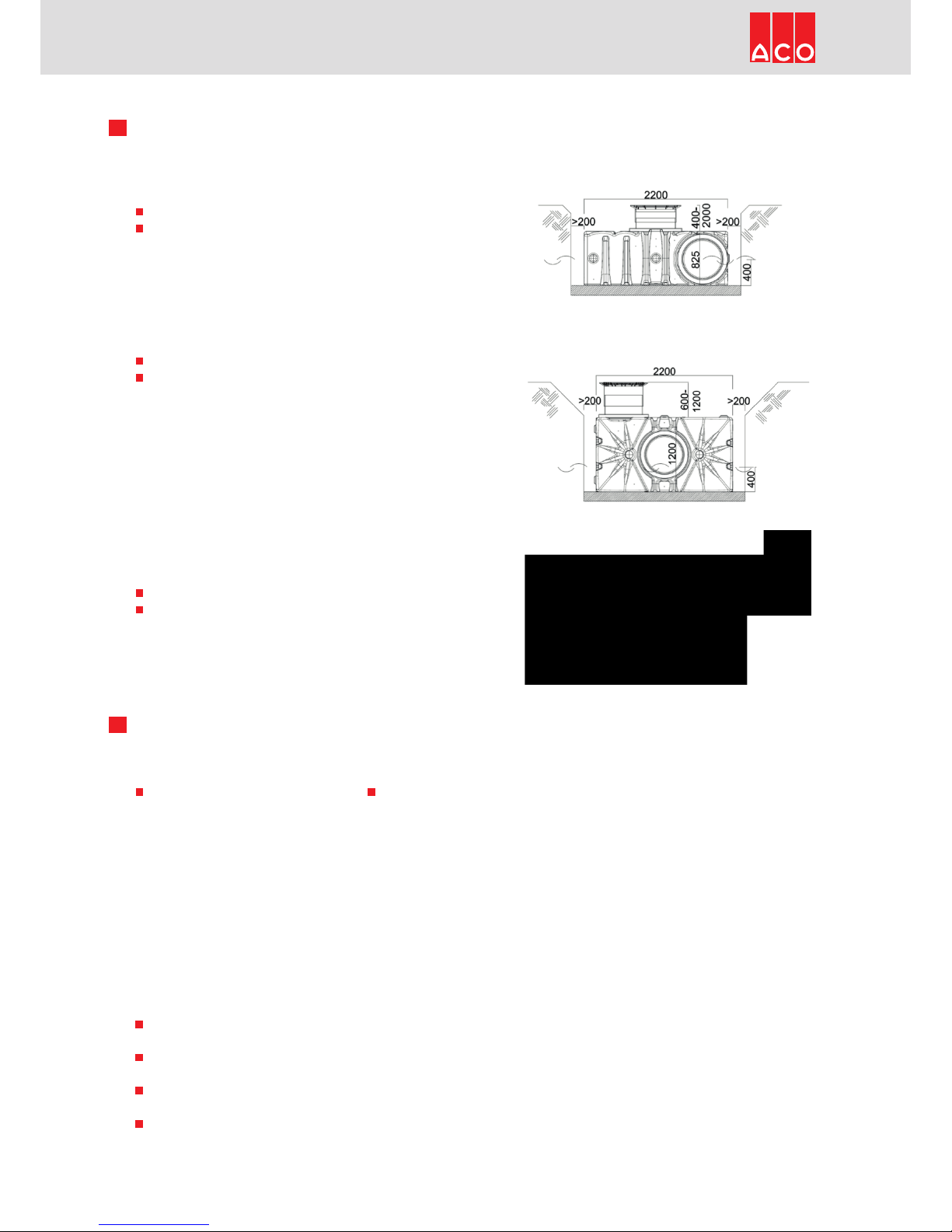
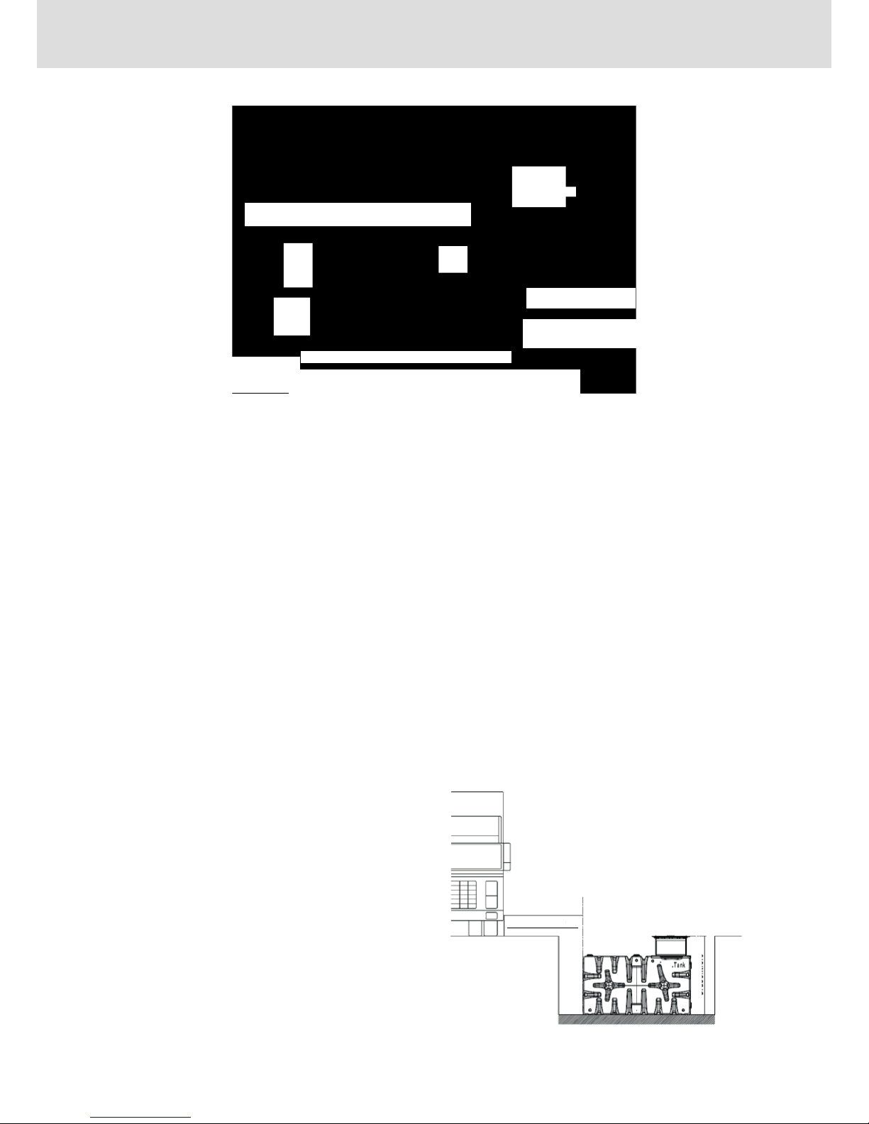
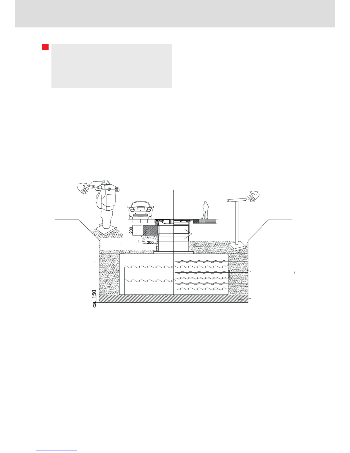
Install the underground tank as
described in the installation
instructions.
Connect the downpipes, which are to
be connected to the underground
tank, to the rainwater inlet at the
underground and connect the overflow
to the drainage sewer, the infiltration
system or other drainage systems.
If you have purchased a house system,
to supply your toilet and/or washing
machine with rainwater, or you would
like to install a level indicator in the
house for your garden system, lay a
DN 100 KG pipe/KG 2000 pipe from
the house connection at the
underground tank to the house service
connection room in the building.
Please ensure that the blank pipe is
laid with at least 2% gradient to the
underground tank, so that
condensation cannot run into the
building. If possible, use max. 30° or
45°bends and branches (e.g. to the
water extraction box), so that the
rainwater hoses do not kink.
A wall penetration seal/gland should
be used to seal the KG pipe in the
house; the seal is inserted directly in
the DN 100 KG pipe.
In the House and Garden packages,
the opening for the water connection
box (if it is not ordered separately)
must be closed off using an
appropriate KG pipe and cover.
The emergency overflow at the top of
the tank must be shortened if
necessary, so that the skimmer edge
lies below any other openings. This
ensures that the surface water flows
away, rather than standing, for
example, in the top tank connection or
in one of the blank pipes
(e.g. to the water extraction box of the
garden packages).
Depending on the features included in
the package, the installation
procedure is as follows:
a) House and Garden Professional:
install the fully automatic rainwater
control in the plant room/service
connection room in the house and lay the
suction (intake) hose from here to the
underground tank (through a correspond-
ing blank pipe)
b) House and Garten Compact:
place the underwater pressure pump in
the underground tank. Use a rotproof
rope or similar to secure the pump from
above in the neck section and to place it
upright in the tank. It also makes it easier
to remove the pump from the tank if
necessary.
Lay the rainwater pressure hose (through
a blank pipe with slope to the
underground tank) from the pump to the
service connection room in the hose and
connect it via a shut-off ball valve to the
rainwater pressure pipe to your toilet,
washing machine, etc.
In the next step you connect the drinking
water pressure pipe to the free drinking
water pressure pipe and connect the inlet
socket of the topup supply to the
underground tank using HT and KG pipes.
IMPORTANT: Ensure slope to the
underground tank! It is advisable to form
a trap as an odour trap. If the top-up pipe
is not positioned with adequate backflow
protection, a backflow safety valve
should be installed. (e.g. ACO Triplex
DN 50, mounted on the wall in front of
the wall penetration). Lay the pump cable
and the cable from the float switch of the
drinking water topup from the under-
ground tank to the service connection
room in the house.
IMPORTANT: Now plug the intermediate
connector of the float switch in the
socket and the connector of the solenoid
valve on the intermediate connector.
IMPORTANT: If there is no water in
the underground tank, water runs
into it until the float switch in the
underground aligns upwards and the
solenoid valve closes.
As soon as there is sufficient water in the
underground tank (pump completely
covered) please plug the connector of
the underwater pressure pump into a
power socket. The system begins to
operate and the pump fills all rainwater
pressure pipes in the house.
IMPORTANT: Check beforehand that
all threaded fasteners, connections,
and hose clamps are properly
tightened. Please ensure that after
all pipes have been filled, the pump
in the underground tank switches off
and only switches on again if you
open a load (toilet flushing).
c) Garden Plus:
Find a suitable place for your water
connection box near the underground
tank and lay a protective pipe/blank pipe,
e.g. KG pipe DN 100/KG 2000 from the
tank to the water connection box. When
laying the blank pipe, it is advisable to lay
the rainwater pressure hose from the
underwater pressure pump to the water
connection box at the same time through
the blank pipe and to connect it to the
ball valve. Now connect the hose to the
pump and lay the pump cable in a reserve
blank pipe to a power socket. Please use
a rotproof rope or similar to secure the
pump at the top of the neck section in the
underground tank. It also makes it easier
to remove the pump if necessary. As
soon as you have tightened all
connections and hose clamps, the ball
valve in the water connection box is
closed and the underground tank is filled
with water, plug the pump connector into
a power socket.
IMPORTANT: The pump starts up and as
soon as the pressure has built up in the
pipe the pump switches off again. If you
now open the ball valve, the pump is
switched on automatically and vice
versa. To make the system winterproof,
disconnect the pump plug from the
power socket and open the ball valve in
the water connection box. Your system is
now winterproof.
d) Garden Basic:
Find a suitable place for your water
connection box near the underground
tank. Lay the suction hose through a KG
pipe/KG 2000 pipe DN 100 laid for this
purpose to the water connection box.
Feed the suction hose through the
perforated bottom of the water
connection box and fix a hose coupling
above the bottom. This prevents the
hose from slipping into the tank. Fill the
pump and the entire suction hose with
water and connect the hose in the water
connection box to the short hose piece
with coupling at the pump (intake side at
front). Connect, e.g. a garden hose, to
the discharge side at the top. As soon as
you now plug the connector into a power
socket and if necessary throw the switch,
the pump pumps water. Disconnect the
connector or throw the switch back to
switch off the pump. To make the system
winterproof, disconnect the suction hose
from the hose piece of the pump and
stow it in the water connection box.
Remove the pump, drain it completely
and place the pump in a dry, frost-free
and well ventilated place. Your system is
now winterproof.

8Note: Installing modular system tanks
Using the prepared openings in the tank
Horizontal installation:
Upright installation:
Garden use only
Inlet
Overflow
House & garden use
Blank pipe for hoses + cable
Overflow
Opening must be closed
Garden use only
House & garden use
Inlet
Opening must be closed
Overflow Overflow
Water extraction box
Blank pipe for hoses + cable
Water extraction box
Plan view
Perspective
Plan view
Perspective

9Inspection and maintenance
Regular inspection and qualified
maintenance increase the operating and
functional reliability, lengthens the use
period and prevents structural damage
and unscheduled repairs. Failure to
comply with the intervals named in the
following can cause impairment of the
system’s functional capability and liability
for resulting damage is cancelled.
The owner of the installation can carry
out the inspections themselves.
Servicing and maintenance must be
carried out by competent persons and
documented.
The following time periods should be
considered:
Actuate the manual emergency seal at any backflow stops installed
Check the wastewater lifting plant, if installed, for operability, leak tightness, external corrosion
Monthly inspection
Check roof outlets and overflows for unobstructed flow and leaktightness; clean dirt traps; check heating if installed
Check roof gutters and downpipes for leaktightness, cleanliness, fixing, heating if installed and protective coating; clean the screens
Visual check of the switching cycle of the non-potable water pump for operability and leaktightness
Test the system controls by monitoring a switching cycle of the pump system
Check odour traps for cleanliness, water level, leaktightness and if applicable, ability to shut them off
Six-monthly inspection
Check the condition of the filter in the filter system
Check the store for cleanliness, leaktightness and stability
Check the safe distance (water level) of the inlet and overflow, if applicable, visual check of the ventilation (air supply and removal)
Compare the level in the store with the level indicator
Check the visible pipes and cables for condition, leaktightness, fixing and corrosion
Check the water meter for function and leaktightness
Check for leaktight connection of the backflow valve/backflow flap (by manual actuation), if installed
Check the wastewater lifting plant for operability, leaktightness, corrosion, if installed
Check any drawing off fittings for leak tightness and possible changes to the water with regard to odour, colour and suspended
substances
Check the flushing operation of flushing devices (toilet cistern, flush valves, etc.), correct the flushing water volume if necessary
Check the marking of all pipes and drawing off points
Yearly inspection
Clean the filter/filters
Controlled trial run of the non-potable water pump with test before, during and after the trial run, electrical fusing of the pump
system according to VDE regulations, possible inlet pressure of the diaphragm tank, leaktightness of the mechanical seal of the
pump, function of the backflow valve, pump and flow noises, leak tightness of the system and fittings, cleanliness of the system,
corrosion of the system parts
Controlled trial run of the system controls with testing before, during and after the trial run:
System switching on and off points, topup water supply (solenoid valve)
IF wastewater lifting plant installed, check for leaktightness, function, check the level switching, set heights of on,
off and alarm level, check the flow preventer for leaktightness
Yearly maintenance
Draining of the rainwater storage tank, cleaning the inside surfaces of the tank, removing any sediment (basic tank)
Maintenance every 10 years

09/2017 Subject to change without notice
9Note: We recommend the ACO Stormbrixx seepage kit for infiltration of
excessive rainwater
Application example
ACO roof gutter mesh ACO Rain4me
rainwater harvesting
ACO Stormbrixx seepage kit
(SUDS) infiltration system
ACO sludge trap
(required for House and Garden
Compact and Professional)
The piping from the tank to the sludge trap
and on to the Stormbrixx must be laid with
at least the same pipe diameter as the
inlet pipes to the tank and with at least 2°
gradient.
ACO Severin Ahlmann
GmbH & Co. KG
P.O. Box 320, 24755 Rendsburg
Am Ahlmannkai, 24782 Büdelsdorf
Germany
Phone +49 4331 354-0
www.aco.com
www.rain4me.aco
Table of contents
Popular Water Heater manuals by other brands

Bosch
Bosch TR4000 4 ET Installation and operating instructions

NTI
NTI Trin & Stor ST Series Installation and operation instructions

Truma
Truma Therme installation instructions

Takagi
Takagi T-K2 Installation manual and owner's guide

Heylo
Heylo EW 18-e Translation of the original instruction manual

Hubbell Electric Heater Company
Hubbell Electric Heater Company HE Operating and maintenance manual