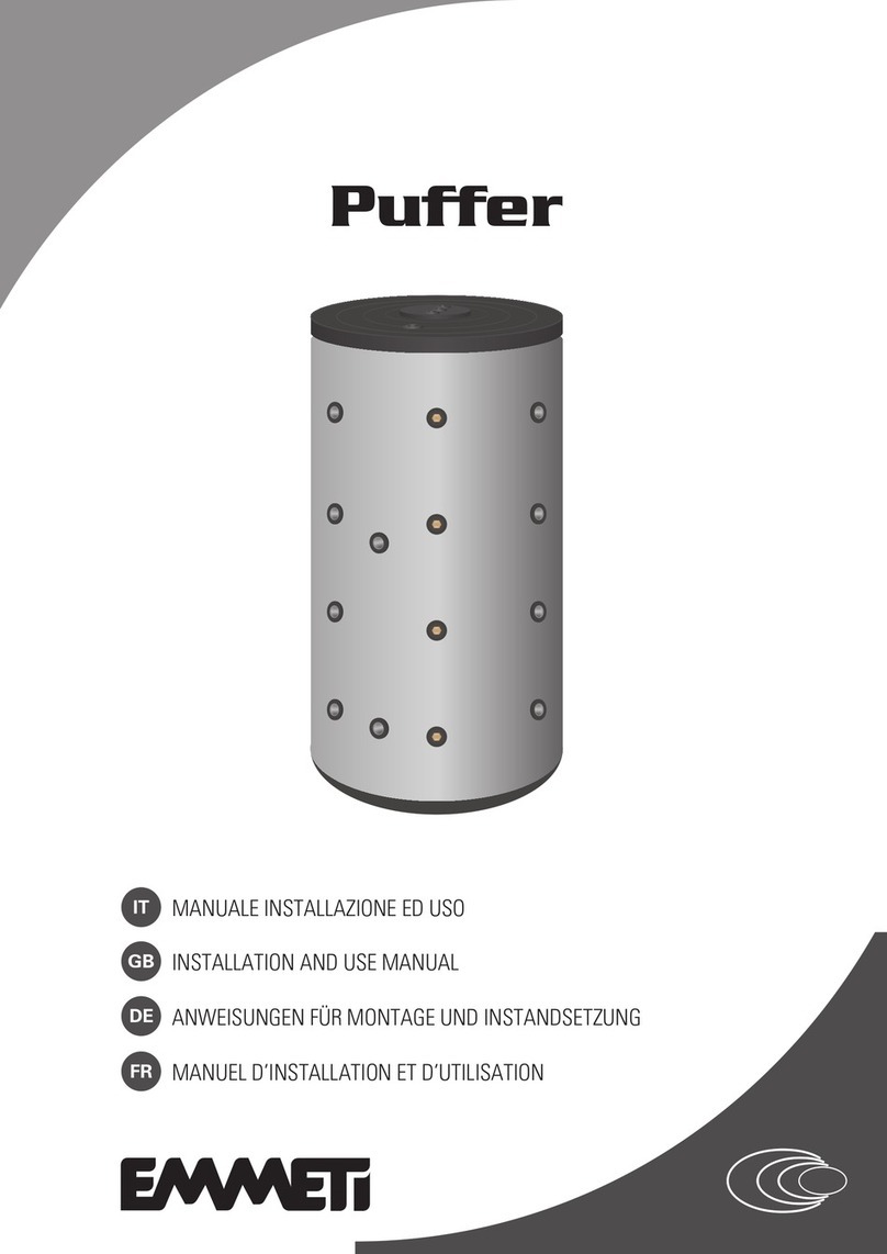
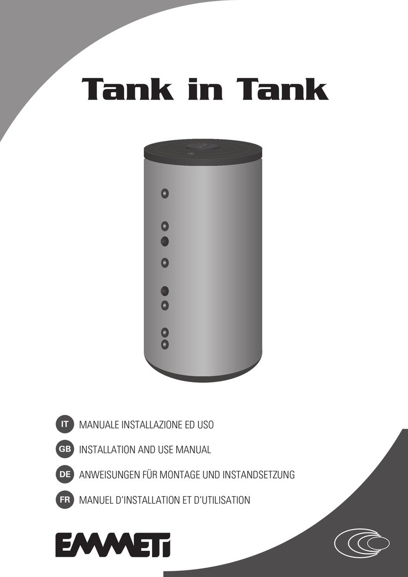
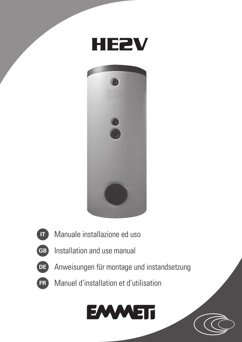
emmeti Comfort S Series Guide

MANUALE INSTALLAZIONE ED USO
IT
INSTALLATION AND USE MANUAL
GB
ANWEISUNGEN FÜR MONTAGE UND INSTANDSETZUNG
DE
FR MANUEL D’INSTALLATION ET D’UTILISATION
Comfort V / Tank /
Comfort S

INDEX
DEDE
página 13
Wir danken Ihnen für das Vertrauen, das Sie unserem Unternehmen durch den
Kauf eines Solar Boiler
Bitte lesen Sie das vorliegende Handbuch vor der ersten Inbetriebnahme des
Gerätes aufmerksam durch und bewahren Sie dieses in dessen unmittelbarer
Nähe auf Solar Boiler.
Die in dieser Veröffentlic
hung enthaltenen Daten können aus technischen
und/oder kommerziellen Anforderungen ohne Voranzeige in jedem beliebigen
Momemt abgeändert werden.
Wichtig!
Die Handbücher an einen trockenem Ort aufbewahren, damit sie min-
destens weitere 10 Jahre für eventuelle Informationen vorhanden sind.
FRFR
page 18
Nous vous remercions de la confiance que vous nous avez accordée en
acquérant le Bouilleur Solaire.
Nous vous invitons à lire attentivement ce manuel dans lequel figurent
toutes les caractéristiques techniques et toutes les informations néces-
saires pour le bon fonctionnement du Bouilleur Solaire.
Les données contenues dans le manuel peuvent faire l’objet de modifica-
tions jugées nécessaires en vue de l’amélioration du produit.
Attention !
Veiller à conserver les manuels à l’abri de l’humidité pour prévenir leur
détérioration et de telle sorte qu’ils puissent être consultés à tout momen
ITIT
pagina 3
Vi ringraziamo per la fiducia concessaci nell’acquisto del Bollitore Solare.
Vi invitiamo a leggere attentamente questo manuale dove sono riportate le
caratteristiche tecniche e tutte le informazioni utili per ottenere un corretto
funzionamento del Bollitore Solare.
I dati possono subire modifiche ritenute necessarie per il miglioramento
del prodotto.
Attenzione!
Conservare i manuali in luogo asciutto per evitare il deterioramento, per
eventuali riferimenti futuri.
GBGB
page 8
Thank you for your choice of Solar Tanks.
Carefully read this manual which contains the specifications and all useful
information for correct operation of Solar Tanks.
Further improvements on product, may introduce, without prior notice,
changes of contents herein.
Warning!
Keep these manuals in a dry place avoiding in this way to spoil them.
1 Descrizione Bollitore ................... 3
2 Indicazioni per l’installazione ....... 7
1 Description Tanks ....................... 8
2 Installation Istructions ............... 12
1 Beschreibung Speicher ................ 13
2 Aufstellungsanweisungen ........... 17
1 Description Bouilleur ................... 18
2 Instructions pour l’installation ... 22
Installazione serpentini rimovibili
Removable exchanger installation
Abnehmbare warmetauscher
Montage serpentin extractible ...... 23
ITIT
GBGB
DEDE
FRFR
FRFR
ITIT
GBGB
DEDE

3
1. TITOLO ITIT
1. DESCRIZIONE BOLLITORE
Bollitore Comfort V a 2 flange 200 - 300 - 500
Dati tecnici
- Pressione massima di esercizio: 10 bar
- Temperatura massima di esercizio continuo accumulo: 95 °C
- Pressione di prova: 15 bar
- Smaltatura inorganica (vetrificazione)
- Isolamento in poliestere flessibile spessore 100 mm
- Rivestimento isolamento in SKY in PVC colore grigio
- Conforme art. 4.3 direttiva PED 2014/68/UE
- Conforme DIN 4753.3 e UNI 10025
Modello u.m. 200 300 500
Capacità totale (Volume utile) ℓ208 285 490
Ø con isolamento A mm 700 700 850
Ø senza isolamento B mm 500 500 650
Altezza C mm 1215 1615 1690
Altezza con isolamento mm 1280 1680 1755
Anodo 1”1/4 D mm 965 1375 1395
Termometro/Sonda/Anodo 1/2" E mm 895 1315 1325
Resistenza elettrica/Ricircolo 1”1/2 F mm 725 1010 1065
Anodo 1”1/4 G mm 485 540 595
Termometro/Sonda/Anodo 1/2” H mm 415 480 525
Ingresso acqua fredda 1”1/2 I mm 245 235 285
Scarico 1”1/4 L mm 140 140 165
Prima flangia DN290 M mm 345 345 395
Seconda flangia DN290 N mm 765 810 865
Termometro/Sonda/Anodo 1/2" O mm - 1010 1065
Termometro/Sonda/Anodo 1/2" P mm 965 1375 1395
Uscita acqua calda 1”1/4 Q mm In alto In alto In alto
Peso a vuoto kg 70 105 145
C
Q
D
E
F
G
H
I
L
O
N
M
P
A
B
100 mm
Nota: nel circuito sanitario in prossimità del bollitore deve essere instal-
lata una valvola di sicurezza con taratura massima = 6 bar e vaso d’espan-
sione adeguato alla volumetria dell’impianto sanitario.

4
1. TITOLO ITIT
Dati tecnici
- Pressione massima di esercizio: 10 bar (8 bar per 1500, 2000 e 3000)
- Temperatura massima di esercizio continuo accumulo: 95 °C
- Pressione di prova: 15 bar (12 bar per 1500, 2000 e 3000)
- Smaltatura inorganica (vetrificazione)
- Isolamento in poliestere flessibile spessore 100 mm
- Rivestimento isolamento in SKY in PVC colore grigio
- Conforme art. 4.3 direttiva PED 2014/68/UE
- Conforme DIN 4753.3 e UNI 10025
C
S
D
E
F
G
H
I
L
M
N
O
P
Q
R
A
B
100 mm
Nota: nel circuito sanitario in prossimità del bollitore deve essere instal-
lata una valvola di sicurezza con taratura massima = 6 bar e vaso d’espan-
sione adeguato alla volumetria dell’impianto sanitario.
Bollitore Comfort V a 3 flange dal 750 al 3.000
Modello u.m. 750 1.000 1.500 2.000 3.000
Capacità totale (Volume utile) ℓ749 955 1430 1990 2848
Ø con isolamento A mm 990 990 1200 1300 1450
Ø senza isolamento B mm 790 790 1000 1100 1250
Altezza Cmm 1810 2140 2120 2425 2650
Altezza con isolamento mm 1875 2205 2155 2470 2680
Anodo 1”1/4 D mm 1500 1830 1720 1990 2180
Termometro/Sonda/Anodo 1/2” E mm 1430 1760 1650 1920 2110
Resistenza elettrica o ricircolo 1”1/2 F mm 1130 1295 1300 1345 1425
Anodo 1”1/4 G mm 670 760 800 820 835
Termometro/Sonda/Anodo 1/2” H mm 600 690 730 750 765
Ingresso acqua fredda 1”1/2 o 2” (*) Imm 350 350 435 410 440
Scarico 1”1/4 L mm 240 240 280 250 235
Prima flangia DN290 M mm 470 470 545 555 550
Termometro/Sonda/Anodo 1/2” N mm - - 760 820 835
Seconda flangia DN290 0 mm 940 1075 1075 1085 1130
Termometro/Sonda/Anodo 1/2” P mm 1130 1295 1290 1345 1425
Terza flangia DN290 Q mm 1320 1610 1505 1670 1800
Termometro/Sonda/Anodo 1/2” R mm 1510 1830 1720 1990 2180
Uscita acqua calda 1”1/2 o 2” (*) Smm In alto In alto In alto In alto In alto
Peso a vuoto kg 195 205 285 350 620
(*) 1”1/2 per modelli fino al 1500, 2” per modelli 2000 e 3000
1. DESCRIZIONE BOLLITORE

5
ITIT
1. DESCRIZIONE BOLLITORE
Dati tecnici
- Pressione massima di esercizio: 6 bar
- Temperatura massima di esercizio continuo accumulo: 70 °C
- Pressione di prova: 9 bar
- Smaltatura organica (trattamento con resine termoindurenti)
- Rivestimento isolamento in SKY in PVC colore grigio
- Isolamento in poliestere flessibile spessore 100 mm
- Conforme art. 4.3 direttiva PED 2014/68/UE
Modello u.m. 1500 2000 3.000
Capacità totale (Volume utile) ℓ1430 1990 2959
Ø con isolamento A mm 1200 1300 1450
Ø senza isolamento B mm 1000 1100 1250
Altezza C mm 2105 2425 2700
Altezza con isolamento mm 2155 2470 2730
Anodo 1”1/4 D mm 1750 1990 2265
Termometro/Sonda/Anodo 1/2” E mm 1680 1920 2195
Resistenza elettrica/Ricircolo 1”1/2 F mm 1295 1345 1455
Anodo 1”1/4 G mm 780 820 865
Termometro/Sonda/Anodo 1/2” H mm 710 750 795
Ingresso acqua fredda 1”1/2 o 2”(*) I mm 395 410 475
Scarico 1”1/4 L mm 180 180 190
Prima Flangia DN290 M mm 530 555 580
Termometro/Sonda/Anodo 1/2” N mm 780 820 865
Seconda Flangia DN290 O mm 1000 1085 1165
Termometro/Sonda/Anodo 1/2” P mm 1295 1345 1455
Terza Flangia DN290 Q mm 1525 1670 1860
Termometro/Sonda/Anodo 1/2” R mm 1750 1990 2265
Uscita acqua calda 1”1/2 o 2”(*) P mm In alto In alto In alto
Peso a vuoto kg 285 350 535
(*) 1”1/2 per modelli fino al 1500, 2” per modelli 2000 e 3000
Bollitore Comfort S a 3 flange dal 1500 al 3.000
Nota: nel circuito sanitario in prossimità del bollitore deve essere instal-
lata una valvola di sicurezza con taratura massima = 6 bar e vaso d’espan-
sione adeguato alla volumetria dell’impianto sanitario.
C
S
D
E
F
G
H
I
L
M
N
O
P
Q
R
A
B
100 mm

6
ITIT
1. DESCRIZIONE BOLLITORE
Dati tecnici
- Pressione massima di esercizio: 10 bar (8 bar per modelli 1500 e 2000)
- Temperatura massima di esercizio continuo accumulo: 95 °C
- Pressione di prova: 15 bar (12 bar per modelli 1500 e 2000)
- Smaltatura inorganica (vetrificazione)
- Isolamento in poliestere flessibile spessore 100 mm
- Rivestimento isolamento in SKY in PVC colore grigio
- Conforme art. 4.3 direttiva PED 2014/68/UE
- Conforme DIN 4753.3 e UNI 10025
Modello u.m. 300 500 750 1000 1500 2000
Capacità totale ℓ285 490 749 955 1430 1990
Ø con isolamento A mm 700 850 990 990 1200 1300
Ø senza isolamento B mm 500 650 790 790 1000 1100
Altezza C mm 1615 1690 1810 2140 2120 2425
Altezza con isolamento mm 1680 1755 1875 2205 2155 2470
Anodo 1”1/4 D mm 1375 1395 1500 1830 1720 1990
Termometro/Sonda/Anodo 1/2” E mm 1315 1325 1430 1760 1650 1920
Resistenza elettrica/Ricircolo 1”1/2 F mm 1010 1065 1130 1295 1300 1345
Anodo 1”1/4 G mm 540 595 670 760 800 820
Termometro/Sonda/Anodo 1/2” H mm 480 525 600 690 730 750
Ingresso acqua fredda 1”1/2 o 2”(*) I mm 235 285 350 350 435 410
Scarico 1”1/4 L mm 140 165 240 240 250 250
Flangia DN290 (***) M mm - - - - - 555
Termometro/Sonda/Anodo 1/2” N mm - - - - 760 820
Termometro/Sonda/Anodo 1/2” O mm 1375 1395 1510 1830 1720 1990
Uscita acqua calda 1”1/4 o 1”1/2” o 2” (**) P mm In alto In alto In alto In alto In alto In alto
Peso a vuoto kg 105 145 195 205 285 350
(*) 1”1/2 per modelli fino al 1500, 2” per modello 2000
(**) 1”1/4 per modelli 300 e 500, 1”1/2 per modelli 750 e 1500, 2” per modello 2000
(***) Flangia DN290 presente solo nel modello 2000
Serbatoi di accumulo vetrificati dal 300 al 2000
Nota: nel circuito sanitario in prossimità del bollitore deve essere instal-
lata una valvola di sicurezza con taratura massima = 6 bar e vaso d’espan-
sione adeguato alla volumetria dell’impianto sanitario.
C
P
D
E O
A
B
F
GN
H
IM
L
100 mm

7
ITIT
2. INDICAZIONI PER L’INSTALLAZIONE
Quanto di seguito riportato è determinante per la validità della
garanzia.
1. L’installazione deve:
– Essere eseguita da un installatore qualificato.
– Prevedere, dove necessario, un riduttore di pressione per l’acqua in
ingresso.
– Prevedere una valvola di sicurezza tarata secondo quanto riportato
nell’etichetta dati tecnici applicata sul boiler.
– Prevedere un vaso espansione (vedi tabella dimensionamento vaso
d’espansione) commisurato alle dimensioni del boiler (si consiglia di
far eseguire il calcolo ad un termotecnico).
2. Prima della messa in funzione è bene verificare il serraggio delle viti
della flangia (applicare coppia pari a 20 Nm).
3. La temperatura del contenuto del boiler deve sempre essere inferiore
a 95 °C (70 °C per i modelli Comfort S).
4. Deve essere eseguita la pulizia interna ogni 12 mesi.
5. Per evitare la corrosione va installato l’anodo elettronico in dotazione
con il bollitore.
6. Come è noto il contatto tra metalli diversi può dar luogo a fenomeni
di corrosione.
In tal senso si consiglia di interporre un opportuno giunto dielettrico
tra gli attacchi posti nel bollitore e le corrispondenti tubazioni.
7. La conducibilità elettrica dell’acqua non deve essere inferiore a 150
μS/cm o superiore a 1000 μS/cm.
Anodo elettronico
I bollitori Comfort V, Comfort S ed i Serbatoi di accumulo vetrificati ven-
gono forniti con nr. 1 anodo elettronico (singolo per i modelli fino al 1000,
doppio per i modelli da 1500 a 3000.
Schema di collegamento
L’anodo ha un attacco da 1/2”M: può risultare necessaria una riduzione
da 1”1/4M a 1/2”F (non fornita) a seconda dell’attacco scelto per l’intal-
lazione dell’anodo elettronico.
Per la messa in funzione dell’anodo elettronico si veda il relativo manuale
fornito a corredo.
Dimensionamento vaso d’espansione
Valori in litri relativi a:
- pressione di precarica pari a 2,5 bar
- pressione taratura valvola di sicurezza pari a 6,0 bar
- espansione da 10 a 90 °C.
Negli impianti con anelli di ricircolo sanitari, si deve considerare anche il
volume d’acqua presente nelle tubazioni.
Volume vaso
d’espansione (I)
Modello bollitore/accumulo
200 300 500 750 1000 1500 2000 3000
40°C 3,1 4,3 7,4 11,2 14,3 21,5 29,8 44,4
50°C 4,9 6,7 11,5 17,6 22,5 33,6 46,8 69,6
60°C 7,0 9,6 16,5 25,2 32,1 48,0 66,8 99,4
70°C 9,4 12,8 22,1 33,7 43,0 64,4 89,6 133,2
80°C 12,0 16,4 28,3 43,2 55,1 82,5 114,8 170,7
90°C 14,9 20,4 35,0 53,5 68,3 102,2 142,2 211,5
Staffa Supporto Led
Apparecchiatura
Elettrodo
Temperatura di accumulo

8
GBGB
Tanks Comfort V - 2 flange 200 - 300 - 500
Technical data
-
Maximum operating pressure: 10 bar exchanger
.
- Maximum continuous operating temperature accumulation: 95 °C.
- Testing pressure: 15 bar.
- Inorganic enamelling (vitrification).
- Insulation: in polyester flexible thickness 100 mm.
- Insulation coating SKY Grey PVC.
- In compliance with directive 2014/68/EU, art. 4.3.
- In compliance with DIN 4753.3 and UNI 10025.
Model u.m. 200 300 500
Total capacity ℓ208 285 490
Ø with insulation A mm 700 700 850
Ø without insulation B mm 500 500 650
Height C mm 1215 1615 1690
Height with insulation mm 1280 1680 1755
Anodo 1”1/4 D mm 965 1375 1395
Thermometer/Probe/Anodo 1/2" E mm 895 1315 1325
Electrical resistance/recirculation 1”1/2 F mm 725 1010 1065
Anodo 1”1/4 G mm 485 540 595
Thermometer/Probe/Anodo 1/2” H mm 415 480 525
Cold water inlet 1”1/2 I mm 245 235 285
Drain 1”1/4 L mm 140 140 165
First Flange DN290 M mm 345 345 395
Second Flange DN290 N mm 765 810 865
Thermometer/Probe/Anodo 1/2" O mm - 1010 1065
Thermometer/Probe/Anodo 1/2" P mm 965 1375 1395
Hot water outlet 1”1/4 Q mm Up Up Up
Empty weight kg 70 105 145
C
Q
D
E
F
G
H
I
L
O
N
M
P
A
B
100 mm
Note: in the sanitary circuit near of the boiler must be installed a safety
valve with calibration maximum = 6 bar and the expansion vessel adapted
to the volume of the sanitary system.
1. DESCRIPTION TANKS

9
1. DESCRIPTION TANKS GBGB
C
S
D
E
F
G
H
I
L
M
N
O
P
Q
R
A
B
100 mm
Note: in the sanitary circuit near of the boiler must be installed a safety
valve with calibration maximum = 6 bar and the expansion vessel adapted
to the volume of the sanitary system.
Tanks Comfort V - 3 flange from 750 to 3.000
Model u.m. 750 ℓ1.000 ℓ1.500 ℓ2.000 ℓ3.000 ℓ
Total capacity ℓ749 955 1430 1990 2848
Ø with insulation Amm 990 990 1200 1300 1450
Ø without insulation Bmm 790 790 1000 1100 1250
Height C mm 1810 2140 2120 2425 2650
Height with insulation mm 1875 2205 2155 2470 2680
Anodo 1”1/4 D mm 1500 1830 1720 1990 2180
Thermometer/Probe/Anodo 1/2” E mm 1430 1760 1650 1920 2110
Electrical resistance/recirculation 1”1/2 F mm 1130 1295 1300 1345 1425
Anodo 1”1/4 G mm 670 760 800 820 835
Thermometer/Probe/Anodo 1/2” H mm 600 690 730 750 765
Cold water inlet 1”1/2 o 2” (*) Imm 350 350 435 410 440
Drain 1”1/4 L mm 240 240 280 250 235
First Flange DN290 M mm 470 470 545 555 550
Thermometer/Probe/Anodo 1/2” N mm - - 760 820 835
Second Flange DN290 0 mm 940 1075 1075 1085 1130
Thermometer/Probe/Anodo 1/2” P mm 1130 1295 1290 1345 1425
Third Flange DN290 Q mm 1320 1610 1505 1670 1800
Thermometer/Probe/Anodo 1/2” R mm 1510 1830 1720 1990 2180
Hot water outlet 1”1/2 o 2” (*) Smm Up Up Up Up Up
Empty weight kg 195 205 285 350 620
(*) 1”1/2 for models up to 1500, 2” for models 2000 and 3000
Technical data
-
Maximum operating pressure: 10 bar exchanger
(8 bar for 1500, 2000
and 3000 ).
- Maximum continuous operating temperature accumulation: 95 °C.
- Testing pressure: 15 bar (12 bar for 1500, 2000 and 3000 )
- Inorganic enamelling (vitrification).
- Insulation: in polyester flexible thickness 100 mm.
- Insulation coating SKY Grey PVC.
- In compliance with directive 2014/68/EU, art. 4.3.
- In compliance with DIN 4753.3 and UNI 10025.

10
GBGB
Technical data
-
Maximum operating pressure:
6 bar
- Maximum continuous operating temperature accumulation: 70 °C
- Testing pressure: 9 bar
- Smaltatura organica (trattamento con resine termoindurenti)
- Inorganic enamelling (vitrification).
- Insulation: in polyester flexible thickness 100 mm.
- Insulation coating SKY Grey PVC.
- In compliance with directive 2014/68/EU, art. 4.3.
- In compliance with DIN 4753.3 and UNI 10025.
Model u.m. 1500 2000 3.000
Total capacity ℓ1430 1990 2959
Ø with insulation A mm 1200 1300 1450
Ø without insulation B mm 1000 1100 1250
Height C mm 2105 2425 2700
Height with insulation mm 2155 2470 2730
Anodo 1”1/4 D mm 1750 1990 2265
Thermometer/Probe/Anodo 1/2” E mm 1680 1920 2195
Electrical resistance/recirculation 1”1/2 F mm 1295 1345 1455
Anodo 1”1/4 G mm 780 820 865
Thermometer/Probe/Anodo 1/2” H mm 710 750 795
Cold water inlet 1”1/2 o 2”(*) I mm 395 410 475
Drain 1”1/4 L mm 180 180 190
First Flange DN290 M mm 530 555 580
Thermometer/Probe/Anodo 1/2” N mm 780 820 865
Second Flange DN290 O mm 1000 1085 1165
Thermometer/Probe/Anodo 1/2” P mm 1295 1345 1455
Third Flange DN290 Q mm 1525 1670 1860
Thermometer/Probe/Anodo 1/2” R mm 1750 1990 2265
Hot water outlet 1”1/2 o 2”(*) P mm In alto In alto In alto
Empty weight kg 285 350 535
(*) 1”1/2 for model 1500, 2” for models 2000 and 3000
Tanks Comfort S - 3 flange from 1500 to 3.000
Note: in the sanitary circuit near of the boiler must be installed a safety
valve with calibration maximum = 6 bar and the expansion vessel adapted
to the volume of the sanitary system..
1. DESCRIPTION TANKS
C
S
D
E
F
G
H
I
L
M
N
O
P
Q
R
A
B
100 mm

11
1. TITOLO ITIT
1. DESCRIPTION TANKS GBGB
Model u.m. 300 ℓ500 ℓ750 ℓ1000 ℓ1500 ℓ2000 ℓ
Total capacity ℓ285 490 749 955 1430 1980
Ø with insulation A mm 700 850 990 990 1200 1300
Ø without insulation B mm 500 650 790 790 1000 1100
Height C mm 1615 1690 1810 2140 2120 2425
Height with insulation mm 1680 1755 1875 2205 2155 2470
Anodo 1”1/4 D mm 1375 1395 1500 1830 1720 1990
Thermometer/Probe/Anodo 1/2” E mm 1315 1325 1430 1760 1650 1920
Electrical resistance/recirculation 1”1/2 F mm 1010 1065 1130 1295 1300 1345
Anodo 1”1/4 G mm 540 595 670 760 800 820
Thermometer/Probe/Anodo 1/2” H mm 480 525 600 690 730 750
Cold water inlet 1”1/2 o 2”(*) I mm 235 285 350 350 435 410
Drain 1”1/4 L mm 140 165 240 240 250 250
Flange DN290 (***) M mm - - - - - 555
Thermometer/Probe/Anodo 1/2” N mm - - - - 760 820
Thermometer/Probe/Anodo 1/2” O mm 1375 1395 1510 1830 1720 1990
Hot water outlet 1”1/4 o 1”1/2” o 2” (**) P mm Up Up Up Up Up Up
Empty weight kg 105 145 195 205 285 350
(*) 1”1/2 for models up to 1500 , 2” for models 2000
(**) 1”1/4 for models 300 and 500 , 1”1/2 for models 750 to 1500, 2” for models 2000
(***) Flange DN 290 only present in the model 2000
Storage tanks vitrified from 300 to 2000
C
P
D
E O
A
B
F
GN
H
IM
L
100 mm
Note: in the sanitary circuit near of the boiler must be installed a safety
valve with calibration maximum = 6 bar and the expansion vessel adapted
to the volume of the sanitary system.
Technical data
-
Maximum operating pressure: 10 bar exchanger
(8 bar for 1500 and
2000).
- Maximum continuous operating temperature accumulation: 95 °C.
- Testing pressure: 15 bar (12 bar for 1500 and 2000)
- Inorganic enamelling (vitrification).
- Insulation: in polyester flexible thickness 100 mm.
- Insulation coating SKY Grey PVC.
- In compliance with directive 2014/68/EU, art. 4.3.
- In compliance with DIN 4753.3 and UNI 10025.

12
ITIT
GBGB
2. INSTALLATION ISTRUCTIONS
What follows determines the validity of the warranty.
1. The installation must:
- Be performed by a qualified installer.
- Include, where necessary, a pressure reducer for the inlet water.
- Include a relief valve calibrated as shown on the technical data label
affixed to the boiler.
- Include an expansion tank (see expansion tank sizing table ) com-
mensurate with the sizes of the boiler (it is recommended to arrange
for the calculations to be performed by a heating engineer).
2. Before start-up check tightening of the flange screws (apply
a torque of 20 Nm).
3. The temperature of the contents of the boiler must always be below
95°C.
4. Internal cleaning must be performed every 12 months.
5. To prevent corrosion the electronic anode supplied with the boiler
must be installed.
6. As is known, contact between different metals can cause corrosion.
In this sense, it is advisable to insert an appropriate dielectric cou-
pling between the attachments located inside the boiler and the
corresponding pipes.
7. The electrical conductivity of the water must not be less than 150 μS/
cm or greater than 1000 μS/cm.
Expansion tank dimensioning
Values in relating to:
- pre-load pressure of 2.5 bar
- relief valve calibration pressure of 6.0 bar
- expansion from 10 to 90°C.
In systems with domestic water recirculation rings, the volume of the
water in the pipes should also be considered.
Expansion tank
volume (I)
Model kettle / accumulation
200 300 500 750 1000 1500 2000 3000
40°C 3,1 4,3 7,4 11,2 14,3 21,5 29,8 44,4
50°C 4,9 6,7 11,5 17,6 22,5 33,6 46,8 69,6
60°C 7,0 9,6 16,5 25,2 32,1 48,0 66,8 99,4
70°C 9,4 12,8 22,1 33,7 43,0 64,4 89,6 133,2
80°C 12,0 16,4 28,3 43,2 55,1 82,5 114,8 170,7
90°C 14,9 20,4 35,0 53,5 68,3 102,2 142,2 211,5
Storage temperature
Bracket Support Led
Equipment
Electrode
Electronic anode
Tanks Comfort V, Comfort S and Storage tanks vitrified are supplied with
nr. 1 electronic anode (single for models until 1000, twice for models from
1500 to 3000 s).
Wiring diagram
The anode has a 1/2 “M: it may be necessary a reduction from 1” 1/ 4M
to 1/2 “F (not supplied) depending on the attack chosen for the intallation
electronic anode.
For the commissioning of the anode electronic see the manual provided.

13
1. TITOLO ITIT
DEDE
1. BESCHREIBUNG SPEICHER
Kessel Comfort V - 2 flansch 200 - 300 - 500
Modelle u.m. 200 300 500
Gesamter Inhalt ℓ208 285 490
Ø mit Isolierung A mm 700 700 850
Ø ohne Isolierung B mm 500 500 650
Höhe C mm 1215 1615 1690
Höhe mit Isolierung mm 1280 1680 1755
Anodo 1”1/4 D mm 965 1375 1395
Thermometer/Sonde/Anodo 1/2" E mm 895 1315 1325
Elektrischer Widerstand/ Umwälzung 1”1/2 F mm 725 1010 1065
Anodo 1”1/4 G mm 485 540 595
Thermometer/Sonde/Anodo 1/2” H mm 415 480 525
Kaltwassereintritt 1”1/2 I mm 245 235 285
Auspuff 1”1/4 L mm 140 140 165
Bevor flansch DN290 M mm 345 345 395
Zweite flansch DN290 N mm 765 810 865
Thermometer/Sonde/Anodo 1/2" O mm - 1010 1065
Thermometer/Sonde/Anodo 1/2" P mm 965 1375 1395
Warmwasseraustritt 1”1/4 Q mm Hoch Hoch Hoch
Leergewicht kg 70 105 145
C
Q
D
E
F
G
H
I
L
O
N
M
P
A
B
100 mm
Technisches Datenblatt
-
Maximaler Betriebsdruck: 10 bar Heizschlange
- Max Betriebstemperatur laufende Abspeicherung: 95 °C
- Testdruck: 15 bar
- Anorganische Emaillierung
- Isolierung: polyester flexibel Stärke 100 mm
- Isolations-Beschichtung SKY PVC grau.
- Gemäß Richtlinie Nr. 2014/68/EU (Art. 4, Abs. 3).
- Gemäß mit DIN 4753.3 und UNI 10025
Anmerkung: In den Sanitärkreislauf in der Nähe des Kessels muss
ein Sicherheitsventil mit der Kalibrierung maximum = 6 bar und das
Ausdehnungsgefäß zu dem Volumen des in das Abwassersystem geei-
gnet installiert werden.

14
1. TITOLO ITIT
DEDE
C
S
D
E
F
G
H
I
L
M
N
O
P
Q
R
A
B
100 mm
Kessel Comfort V - 3 flansche von 750 bis 3.000
Modelle u.m. 750 1.000 1.500 2.000 3.000
Gesamter Inhalt ℓ749 955 1430 1990 2848
Ø mit Isolierung Amm 990 990 1200 1300 1450
Ø ohne Isolierung Bmm 790 790 1000 1100 1250
Höhe C mm 1810 2140 2120 2425 2650
Höhe mit Isolierung mm 1875 2205 2155 2470 2680
Anodo 1”1/4 D mm 1500 1830 1720 1990 2180
Thermometer/Sonde/Anodo 1/2” E mm 1430 1760 1650 1920 2110
Elektrischer Widerstand/ Umwälzung 1”1/2 F mm 1130 1295 1300 1345 1425
Anodo 1”1/4 G mm 670 760 800 820 835
Thermometer/Sonde/Anodo 1/2” H mm 600 690 730 750 765
Kaltwassereintritt 1”1/2 o 2” (*) Imm 350 350 435 410 440
Auspuff 1”1/4 L mm 240 240 280 250 235
Bevor flansch DN290 M mm 470 470 545 555 550
Thermometer/Sonde/Anodo 1/2” N mm - - 760 820 835
Zweite flansch DN290 0 mm 940 1075 1075 1085 1130
Thermometer/Sonde/Anodo 1/2” P mm 1130 1295 1290 1345 1425
Dritte flansch DN290 Q mm 1320 1610 1505 1670 1800
Thermometer/Sonde/Anodo 1/2” R mm 1510 1830 1720 1990 2180
Warmwasseraustritt 1”1/2 o 2” (*) Smm Hoch Hoch Hoch Hoch Hoch
Leergewicht kg 195 205 285 350 620
(*) 1“ 1/2 für Modelle bis zu 1500 , 2” für die Modelle 2000 und 3000
Technisches Datenblatt
-
Maximaler Betriebsdruck: 10 bar Heizschlange (8 bar für 1500, 2000 und
3000 )
- Max Betriebstemperatur laufende Abspeicherung: 95 °C
- Testdruck: 15 bar (12 bar für 1500, 2000 und 3000 )
- Anorganische Emaillierung
- Isolierung: polyester flexibel Stärke 100 mm
- Isolations-Beschichtung SKY PVC grau.
- Gemäß Richtlinie Nr. 2014/68/EU (Art. 4, Abs. 3).
- Gemäß mit DIN 4753.3 und UNI 10025
Anmerkung: In den Sanitärkreislauf in der Nähe des Kessels muss
ein Sicherheitsventil mit der Kalibrierung maximum = 6 bar und das
Ausdehnungsgefäß zu dem Volumen des in das Abwassersystem geei-
gnet installiert werden.
1. BESCHREIBUNG SPEICHER

15
DEDE
1. BESCHREIBUNG SPEICHER
Technisches Datenblatt
-
Maximaler Betriebsdruck: 6 bar Heizschlange
- Max Betriebstemperatur laufende Abspeicherung: 70 °C
- Testdruck: 9 bar
- Anorganische Emaillierung
- Isolierung: polyester flexibel Stärke 100 mm
- Isolations-Beschichtung SKY PVC grau.
- Gemäß Richtlinie Nr. 2014/68/EU (Art. 4, Abs. 3).
- Gemäß mit DIN 4753.3 und UNI 10025
Modelle u.m. 1500 2000 3.000
Gesamter Inhalt ℓ1430 1990 2959
Ø mit Isolierung A mm 1200 1300 1450
Ø ohne Isolierung B mm 1000 1100 1250
Höhe C mm 2105 2425 2700
Höhe mit Isolierung mm 2155 2470 2730
Anodo 1”1/4 D mm 1750 1990 2265
Thermometer/Sonde/Anodo 1/2” E mm 1680 1920 2195
Elektrischer Widerstand/ Umwälzung 1”1/2 F mm 1295 1345 1455
Anodo 1”1/4 G mm 780 820 865
Thermometer/Sonde/Anodo 1/2” H mm 710 750 795
Kaltwassereintritt 1”1/2 o 2”(*) I mm 395 410 475
Auspuff 1”1/4 L mm 180 180 190
Bevor flansch DN290 M mm 530 555 580
Thermometer/Sonde/Anodo 1/2” N mm 780 820 865
Zweite flansch DN290 O mm 1000 1085 1165
Thermometer/Sonde/Anodo 1/2” P mm 1295 1345 1455
Dritte flansch DN290 Q mm 1525 1670 1860
Thermometer/Sonde/Anodo 1/2” R mm 1750 1990 2265
Warmwasseraustritt 1”1/2 o 2”(*) P mm Hoch Hoch Hoch
Leergewicht kg 285 350 535
(*) 1“ 1/2 für Modell von 1500, 2” für die Modelle 2000 und 3000
Kessel Comfort S a 3 flansche von 1500 bis 3.000
Anmerkung: In den Sanitärkreislauf in der Nähe des Kessels muss
ein Sicherheitsventil mit der Kalibrierung maximum = 6 bar und das
Ausdehnungsgefäß zu dem Volumen des in das Abwassersystem geei-
gnet installiert werden.
C
S
D
E
F
G
H
I
L
M
N
O
P
Q
R
A
B
100 mm

16
1. BESCHREIBUNG SPEICHER DEDE
Modelle u.m. 300 500 750 1000 1500 2000
Gesamter Inhalt ℓ285 490 749 955 1430 1980
Ø mit Isolierung A mm 700 850 990 990 1200 1300
Ø ohne Isolierung B mm 500 650 790 790 1000 1100
Höhe C mm 1615 1690 1810 2140 2120 2425
Höhe mit Isolierung mm 1680 1755 1875 2205 2155 2470
Anodo 1”1/4 D mm 1375 1395 1500 1830 1720 1990
Thermometer/Sonde/Anodo 1/2” E mm 1315 1325 1430 1760 1650 1920
Elektrischer Widerstand/ Umwälzung 1”1/2 F mm 1010 1065 1130 1295 1300 1345
Anodo 1”1/4 G mm 540 595 670 760 800 820
Thermometer/Sonde/Anodo 1/2” H mm 480 525 600 690 730 750
Kaltwassereintritt 1”1/2 o 2”(*) I mm 235 285 350 350 435 410
Auspuff 1”1/4 L mm 140 165 240 240 250 250
Flansch DN290 (***) M mm - - - - - 555
Thermometer/Sonde/Anodo 1/2” N mm - - - - 760 820
Thermometer/Sonde/Anodo 1/2” O mm 1375 1395 1510 1830 1720 1990
Warmwasseraustritt
1”1/4 o 1”1/2” o 2” (**)
P mm Hoch Hoch Hoch Hoch Hoch Hoch
Leergewicht kg 105 145 195 205 285 350
(*) 1 “1/2 für Modelle bis zu 1500 , 2” Modell 2000
(**) 1 “1/4 für Modelle von 300 bis 500 , 1” 1/2 für die Modelle von 750 bis 1500 , 2“ Modell 2000
(***) Flansch DN 290 nur im Modell 2000 vorhanden
Speichertanks verglast von 300 bis 2000
C
P
D
E O
A
B
F
GN
H
IM
L
100 mm
Technisches Datenblatt
-
Maximaler Betriebsdruck: 10 bar Heizschlange (8 bar für 1500 und 2000 )
- Max Betriebstemperatur laufende Abspeicherung: 95 °C
- Testdruck: 15 bar (12 bar für 1500 und 2000 )
- Anorganische Emaillierung
- Isolierung: polyester flexibel Stärke 100 mm
- Isolations-Beschichtung SKY PVC grau.
- Gemäß Richtlinie Nr. 2014/68/EU (Art. 4, Abs. 3).
- Gemäß mit DIN 4753.3 und UNI 10025
Anmerkung: In den Sanitärkreislauf in der Nähe des Kessels muss
ein Sicherheitsventil mit der Kalibrierung maximum = 6 bar und das
Ausdehnungsgefäß zu dem Volumen des in das Abwassersystem geei-
gnet installiert werden.

17
1. TITOLO DEDE
2. AUFSTELLUNGSANWEISUNGEN
Folgende Anweisungen müssen genauestens befolgt werden,
damit die Garantie gültig ist.
1. Die Montage muss:
- Von einem qualifiziertem Monteur ausgeführt werden.
- Falls notwendig, muss ein Druckminderer für das Zulaufwasser einge-
baut werden.
- Es muss gemäß dem Typenschild (technischen Daten), das am
Wasserkessel befestigt ist, ein geeichtes Sicherheitsventil eingebaut
werden.
- Es muss gemäß der Größe des Wasserkessels ein entsprechendes
Ausdehnungsgefäß (siehe Tabelle bezüglich Ausdehnungsgefäß-
Dimensionierung). Wir empfehlen Ihnen die Berechnung von einem
Wärmetechniker durchführen zu lassen.
2. Bevor das Gerät in Betrieb genommen wird, müssen Sie sicherstellen,
dass die Schrauben des Flansches (mit einem Drehmoment von 20 Nm)
ordnungsgemäß angezogen sind.
3. Die Temperatur des Wasserkesselinhaltes muss immer unter 95°C
liegen.
4. Alle 12 Monte muss das Innere des Kessels gereinigt werden.
5. Um Korrosion zu vermeiden, muss die mit dem Kessel mitgelieferte
elektronische Anode installiert werden.
6. Wie bekannt ist, kann der Kontakt verschiedener Metalle zu Korrosion
führen.
Daher empfehlen wir Ihnen ein dielektrisches Verbindungsstück
zwischen dem Kesselanschluss und der entsprechenden Leitung ein-
zubauen.
7. Die elektrische Leitfähigkeit des Wasser darf nicht 150 μS/cm unter-
schreiten oder 1000 μS/cm überschreiten.
Elektronische Anode
Die Kessel Comfort V, Comfort S und Tanks keramisch mit nr kommen. 1
elektronische Anode (Einzel für Modelle zu 1000, zweimal für Modelle von
1500 bis 3000).
Anschlussplan
Die Anode hat eine 1/2 “M: kann es notwendig sein, bis 1” 1/ 4M zu 1/2
“F (nicht mitgeliefert) in Abhängigkeit von der für die intallation elektroni-
sche Anode gewählt Angriff.
Für die Inbetriebnahme der Anode elektronisch finden Sie im Handbuch
zur Verfügung gestellt.
Abmessungen des Ausdehnungsgefäß
Angaben in zu:
- Vorspanndruck von 2,5 bar
- Einstellungsdruck Sicherheitsventil entspricht 6,0 bar
- Ausdehnung von 10°C bis 90°C
Bei den Rücklaufanlagen im Sanitärbereich muss auch das im Rohr vor-
handene Wasservolumen berücksichtigt werden.
Volumen des
Ausdehnungsgefäßes
Modell Kessel / Akkumulation
200 300 500 750 1000 1500 2000 3000
40°C 3,1 4,3 7,4 11,2 14,3 21,5 29,8 44,4
50°C 4,9 6,7 11,5 17,6 22,5 33,6 46,8 69,6
60°C 7,0 9,6 16,5 25,2 32,1 48,0 66,8 99,4
70°C 9,4 12,8 22,1 33,7 43,0 64,4 89,6 133,2
80°C 12,0 16,4 28,3 43,2 55,1 82,5 114,8 170,7
90°C 14,9 20,4 35,0 53,5 68,3 102,2 142,2 211,5
Sammeltemperatur
Haltebügel LED
Gerät
Elektrode

18
FRFR
1. DESCRIPTION BOUILLER
Bouiller Comfort V avec 2 bride 200 - 300 - 500
Données Techniques
-
Pression maximale de fonctionnement: 10 bar serpentin.
- Température maximale de fonctionnement continue d’accumulation: 95 °C
- Pression d’essai: 15 bar
- Émaillage inorganique
- Isolation: en polyester flexible d’épaisseur 100 mm
- Revêtement d’isolation SKY PVC gris.
- Conforme aux art. 4 paragraphe 3 Directive 2014/68/UE
- Conforme DIN 4753.3 et UNI 10025
Modèle u.m. 200 300 500
Capacité total ℓ208 285 490
Ø avec isolation A mm 700 700 850
Ø sans isolation B mm 500 500 650
Hauteur C mm 1215 1615 1690
Hauteur isolation mm 1280 1680 1755
Anodo 1”1/4 D mm 965 1375 1395
Thermomètre/Sonde/Anodo 1/2" E mm 895 1315 1325
Résistance électrique/Recirculation 1”1/2 F mm 725 1010 1065
Anodo 1”1/4 G mm 485 540 595
Thermomètre/Sonde/Anodo 1/2” H mm 415 480 525
Entrée eau froide 1”1/2 I mm 245 235 285
Échappement 1”1/4 L mm 140 140 165
Première bride DN290 M mm 345 345 395
Seconde bride DN290 N mm 765 810 865
Thermomètre/Sonde/Anodo 1/2" O mm - 1010 1065
Thermomètre/Sonde/Anodo 1/2" P mm 965 1375 1395
Sortie d’eau chaude 1”1/4 Q mm En haut En haut En haut
Poids à vide kg 70 105 145
C
Q
D
E
F
G
H
I
L
O
N
M
P
A
B
100 mm
Remarque: dans le circuit sanitaire au voisinage de la chaudière doit
être installée une soupape de sûreté avec étalonnage maximale = 6 bar
et le vase d’expansion adapté au volume du système sanitaire.

19
FRFR
C
S
D
E
F
G
H
I
L
M
N
O
P
Q
R
A
B
100 mm
Remarque: dans le circuit sanitaire au voisinage de la chaudière doit
être installée une soupape de sûreté avec étalonnage maximale = 6 bar
et le vase d’expansion adapté au volume du système sanitaire.
Bouiller Comfort V avec 3 bride de 750 à 3.000
Modèle u.m. 750 1.000 1.500 2.000 3.000
Capacité total ℓ749 955 1430 1990 2848
Ø avec isolation Amm 990 990 1200 1300 1450
Ø sans isolation Bmm 790 790 1000 1100 1250
Hauteur C mm 1810 2140 2120 2425 2650
Hauteur isolation mm 1875 2205 2155 2470 2680
Anodo 1”1/4 D mm 1500 1830 1720 1990 2180
Thermomètre/Sonde/Anodo 1/2” E mm 1430 1760 1650 1920 2110
Résistance électrique/Recirculation 1”1/2 F mm 1130 1295 1300 1345 1425
Anodo 1”1/4 G mm 670 760 800 820 835
Thermomètre/Sonde/Anodo 1/2” H mm 600 690 730 750 765
Entrée eau froide 1”1/2 o 2” (*) Imm 350 350 435 410 440
Échappement 1”1/4 L mm 240 240 280 250 235
Première bride DN290 M mm 470 470 545 555 550
Thermomètre/Sonde/Anodo 1/2” N mm - - 760 820 835
Seconde bride DN290 0 mm 940 1075 1075 1085 1130
Thermomètre/Sonde/Anodo 1/2” P mm 1130 1295 1290 1345 1425
Tiers bride DN290 Q mm 1320 1610 1505 1670 1800
Thermomètre/Sonde/Anodo 1/2” R mm 1510 1830 1720 1990 2180
Sortie d’eau chaude 1”1/2 o 2” (*) Smm En haut En haut En haut En haut En haut
Poids à vide kg 195 205 285 350 620
(*) 1 “1/2 pour les modèles jusqu’à 1500, 2” pour les modèles de 2000 à 3000
Données Techniques
-
Pression maximale de fonctionnement: 10 bar serpentin (8 bar pour
1500, 2000 et 3000)
- Température maximale de fonctionnement continue d’accumulation: 95 °C
- Pression d’essai: 15 bar (12 bar pour 1500, 2000 et 3000)
- Émaillage inorganique
- Isolation: en polyester flexible d’épaisseur 100 mm
- Revêtement d’isolation SKY PVC gris.
- Conforme aux art. 4 paragraphe 3 Directive 2014/68/UE
- Conforme DIN 4753.3 et UNI 10025
1. DESCRIPTION BOUILLER

20
FRFR
1. DESCRIPTION BOUILLER
Modèle u.m. 1500 2000 3.000
Capacité total ℓ1430 1990 2959
Ø avec isolation A mm 1200 1300 1450
Ø sans isolation B mm 1000 1100 1250
Hauteur C mm 2105 2425 2700
Hauteur isolation mm 2155 2470 2730
Anodo 1”1/4 D mm 1750 1990 2265
Thermomètre/Sonde/Anodo 1/2” E mm 1680 1920 2195
Résistance électrique/Recirculation 1”1/2 F mm 1295 1345 1455
Anodo 1”1/4 G mm 780 820 865
Thermomètre/Sonde/Anodo 1/2” H mm 710 750 795
Entrée eau froide 1”1/2 o 2”(*) I mm 395 410 475
Échappement 1”1/4 L mm 180 180 190
Bride DN290 M mm 530 555 580
Thermomètre/Sonde/Anodo 1/2” N mm 780 820 865
Seconde bride DN290 O mm 1000 1085 1165
Thermomètre/Sonde/Anodo 1/2” P mm 1295 1345 1455
Tiers bride DN290 Q mm 1525 1670 1860
Thermomètre/Sonde/Anodo 1/2” R mm 1750 1990 2265
Sortie d’eau chaude 1”1/2 o 2”(*) En haut En haut En haut
Poids à vide kg 285 350 535
(*) 1 “1/2 pour modèle 1500, 2” pour modèles 2000 en 3000
Données Techniques
-
Pression maximale de fonctionnement: 10 bar serpentin (8 bar pour 1500
et 2000)
- Température maximale de fonctionnement continue d’accumulation: 95 °C
- Pression d’essai: 15 bar (12 bar pour 1500 et 2000)
- Émaillage inorganique
- Isolation: en polyester flexible d’épaisseur 100 mm
- Revêtement d’isolation SKY PVC gris.
- Conforme aux art. 4 paragraphe 3 Directive 2014/68/UE
- Conforme DIN 4753.3 et UNI 10025
Remarque: dans le circuit sanitaire au voisinage de la chaudière doit
être installée une soupape de sûreté avec étalonnage maximale = 6 bar
et le vase d’expansion adapté au volume du système sanitaire.
Bouiller Comfort S avec 3 bride de 1500 à 3.000
C
S
D
E
F
G
H
I
L
M
N
O
P
Q
R
A
B
100 mm
This manual suits for next models
19
Table of contents
Languages:
Other emmeti Water Heater manuals
Popular Water Heater manuals by other brands

Drazice
Drazice NADO 500/200v7 Operation and installation manual

clage
clage DCX operating instructions

PVI Industries
PVI Industries 375P225A-TPL Specifications

Lochinvar
Lochinvar EcoShield SHW60-325CE Installation, commissioning and maintenance instructions

Raritan
Raritan 1700 Series Installation and maintenance instructions

Paloma
Paloma PH-28RIFSN Engineering handbook