4
Technical Information
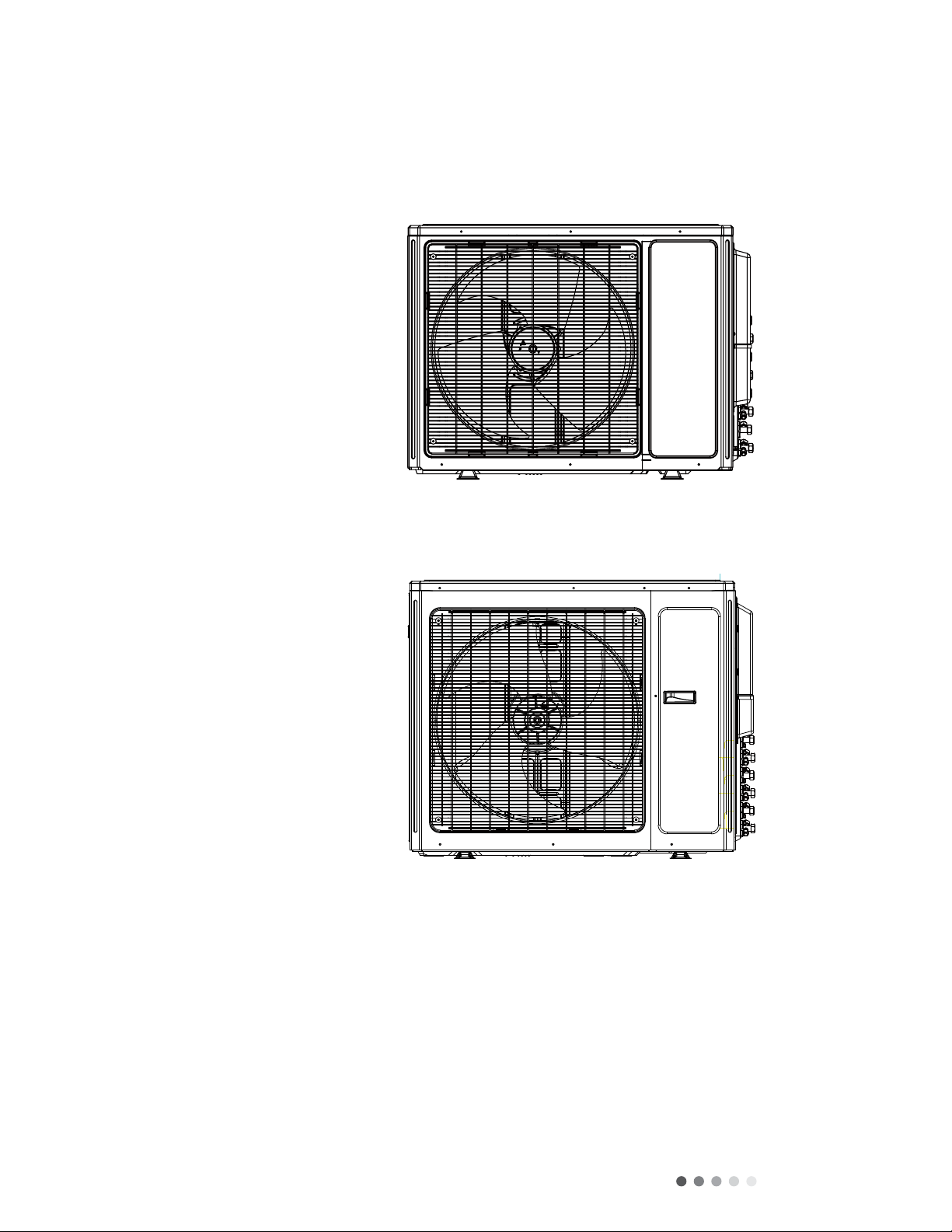
Model AWHD(24)ND3GO
Product Code CB228W07800
Power Supply
Rated Voltage V~ 208/230
Rated Frequency Hz 60
Phases 1
Cooling Capacity (max~min) Btu/h 24000(7500~33000)
Heating Capacity (max~min) Btu/h 26000(7500~35000)
Cooling Power Input (max~min) W 1920
Heating Power Input (max~min) W 2050
Cooling Current Input A 8.35
Heating Current Input A8.9
Rated Power Input W 4550
Current Breaker A 35
EER (Btu/h)/W 12.5
COP (Btu/h)/W 12.7
Outdoor Unit
CompressorTrademark ZHUHAI LANDA COMPRESSOR CO.LTD
Compressor Model QXAS-D23zX090B
Compressor Refrigerant Oil Type RB68EP
CompressorType Inverter Rotary
L.R.A A /
Compressor Rated Load Amp (RLA) A 15.82
Compressor Power Input W 2550
CompressorThermal Protector 1NT11L—6233
Throttling Method Electron expansion valve
Cooling Operation Ambient
Temperature Range F -0.4~118.4
Heating Operation Ambient Temperature Range F -4~75.2
Condenser Material Aluminum Fin-copperTube
Condenser Pipe Diameter inch Φ2/7
Rows-Fin Gap(mm) inch 2-1/18
Coil length (l) X height (H) X coil width (L) inch 38 21/32X1 1/2X29 7/16
Fan Motor Speed (rpm) (H/M/L) rpm 800
Output of Fan Motor W 90
Fan Motor RLA A0.59
Fan Motor Capacitor μF /
Air Flow Volume of Outdoor Unit 2354
Fan Type-Piece CFM Axial-flow
Fan Diameter Φ21 43/64-2 39/64
Defrosting Method inch Automatic Defrosting
ClimateType T1
Isolation I
Moisture Protection IPX4
Permissible Excessive Operating Pressure for the
Discharge Side MPa 4.3
Permissible Excessive Operating Pressure for the
Suction Side MPa 2.5
Dimension (WXHXD) inch 38 37/64X31 7/64X17 21/64
Dimension of Package (LXWXH) inch 42 1/2X19X33
Dimension of Package (LXWXH) inch 42 43/64X19 13/64X33 43/64
Net Weight lb 153.2
Gross Weight lb 164.3
Refrigerant Charge R410A
Refrigerant Charge oz 77.6