ACR Electronics RCL-50 LED Installation instructions

CAUTION: Before proceeding to install, test or use your new ACR
Electronics product, please read this Product Support Manual in its entirety.

2
Table of Contents
SECTION 1- FOREWORD _____________________________________ 3
SECTION 2- GENERAL________________________________________ 4
SECTION 3- SEARCHLIGHT ____________________________________ 4
SECTION 4- REMOTE CONTROL SYSTEM_________________________ 5
SECTION 5- URP-102 POINT PAD™ _____________________________ 5
SECTION 6- URC-103 Master Controller _________________________ 9
APPENDIX A- SPECIFICATIONS
APPENDIX B- PRODUCT COMPONENTS ________________________ 14
APPENDIX C- ACCESSORY COMPONENTS_______________________ 15
PLEASE READ ALL WARNINGS, CAUTIONS AND
NOTES CAREFULLY

3
RCL-50 LED, 12/24V
REMOTE CONTROL SEARCHLIGHT SYSTEM
Figure 1- Remote Control Searchlight System
SECTION 1 - FOREWORD
Congratulations and thank you for purchasing the ACR RCL-50 LED Searchlight.
The RCL-50 LED has been tested extensively to ensure it can survive the
harshest environmental conditions. This assures that the products we offer stand
up to the tough marine environment. With proper care and maintenance your
searchlight will be in service for years to come.
ACR is proud to be AS9100:2008 certified, the International Standard for Quality.
SEARCHLIGHT
URC-103
Controller
URP-102
Point Pad

4
SECTION 2 - GENERAL
The RCL-50 LED was specially designed for mariners who require a high
intensity remote controlled searchlight that can stand up to the tough marine
environment.
The RCL-50 LED 12/24V searchlight system contains a narrow beam searchlight
that produces approximately 100,000 peak candle power using a power efficient
LED module.
All functions of the searchlight can be electrically operated by remote control
from the pilot area of the vessel using the URP-102 Point Pad™, URC-103
Master Controller, and interconnect cable supplied with the RCL-50 LED.
Searchlights equipped with the URC-103 Master Controller have ACR’s unique
XRCiZ™feature. The XRCiZ™feature routinely automatically operates all
moving parts in the searchlight to keep the motors and drive mechanism freely
running.
SECTION 3 - SEARCHLIGHT
The sleek design and modern construction of the searchlight body makes it
attractive for recreational and commercial vessels. The searchlight is totally
enclosed and is made of rugged aluminum alloy. It is gasketed and finished to
be resistant to the weather.
Mounting
Make sure the area is clean and dry. The searchlight can be mounted where
desired, using appropriate length 3/16" diameter, stainless steel fasteners. Four
(4) nylon shoulder washers are supplied with the RCL-50 LED searchlight. The
nylon washers prevent a galvanic reaction between the mounting hardware and
the base of the searchlight. Be sure these washers have been inserted in the
base mounting holes and that the mounting base gasket is securely in place
before bolting down. Silicone grease should be applied to the bottom of the
gasket to help in waterproofing the unit. When mounting, be sure that the
searchlight is able to rotate 360° without hitting any obstructions. For the drilling
hole pattern, refer to the searchlight mounting template, supplied in the mounting
templates.
CAUTION: Do not mount the searchlight upside down. Moisture will not be
able to drain from the inverted light head assembly.
NOTE: The searchlight should be left uncovered if the XRCiZ™ feature is
enabled.

5
SECTION 4 - REMOTE CONTROL SYSTEM
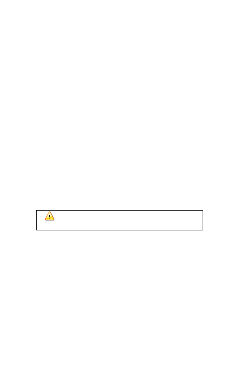
The Remote Control System consists of the URC-103 Master Controller and the
URP-102 Point Pad™. This system is compatible with 12 VDC and 24 VDC
systems without modification. The remote control system may be used with 12
V or 24 V searchlights.
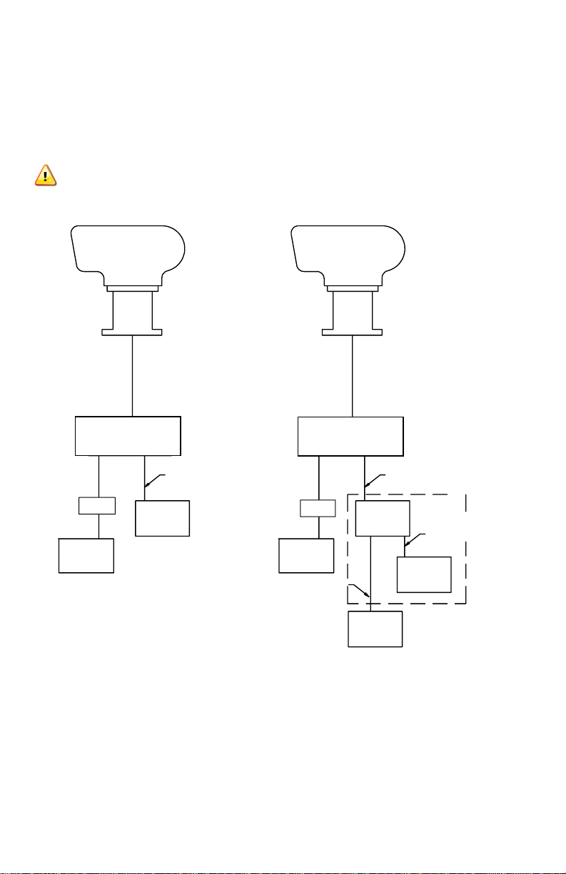
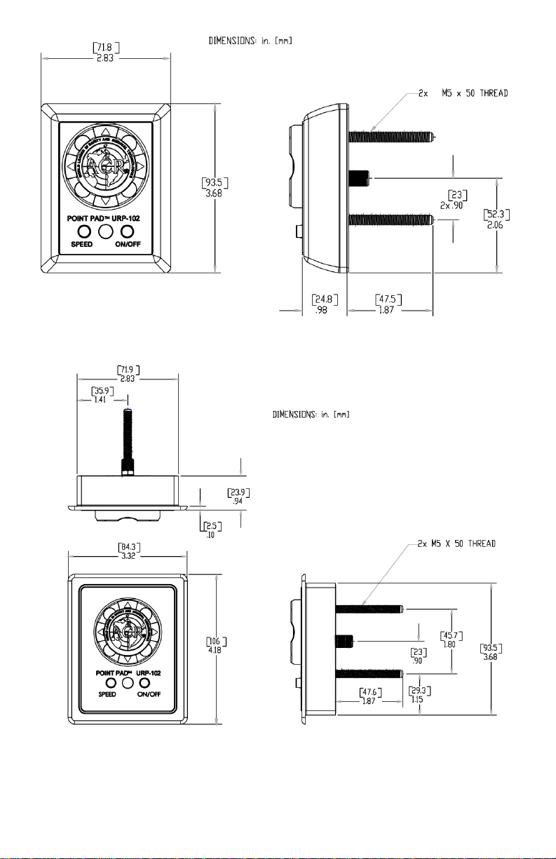
SECTION 5 - URP-102 POINT PAD™
Case Options
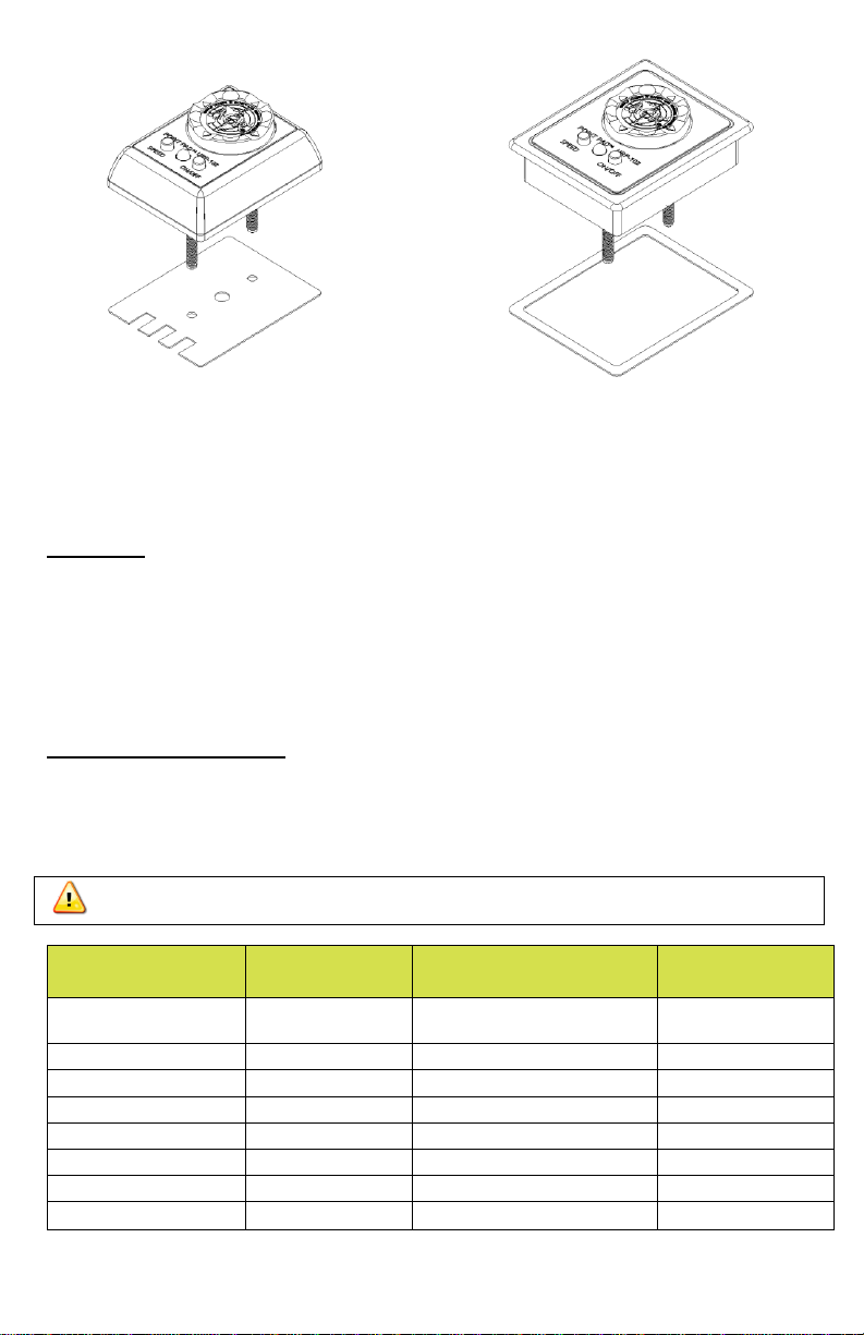
The URP-102 Point Pad™ is supplied as a surface mount unit (see Figure 4). A
flush mount option is provided (see Figure 5). To switch mounting options,
unscrew the six (6) screws on the unit’s back plate and remove the front cover.
Fit the Point Pad™ with the flush mount cover, replace the back plate, and screw
the unit back together.
Mounting
Both the surface mount and flush mount options require access to the backside
of the mounting location. Make sure there are no obstructions behind the area
where the switch is to be located (e.g. bulkheads, wires, plumbing, or hardware).
Check in advance that the coax cable from the master controller can be routed
to this location. Generally, the Point Pad™ should be mounted in a protected
area.
Install the surface mount Point Pad™ by drilling three (3) holes in the dashboard
location using the Point Pad™ surface mount template supplied. Mount the Point
Pad™ to the dashboard using the gasket, washers, and nuts supplied. Use a
sealant around the bolt holes to protect from moisture intrusion.
When the flush mount option is selected, cut a rectangular hole in the dashboard
location using the point pad™ flush mount template supplied in the mounting
templates. Use the gasket, washers, nuts, and the two U-clamps provided to
secure the Point Pad™. Use a sealant around the cut out to protect from
moisture intrusion.
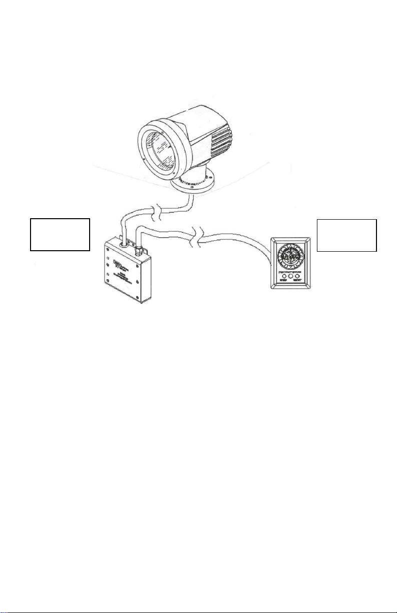
Connecting to the Master Controller
The Point Pad™ communicates with the Master Controller via standard
television type RG-59 coaxial cable. The connectors are standard "F" type
television connectors. The connector on the back of the Point Pad™ is located
in the center of the panel for ease of installation. After the coax cable has been
routed and the “F” connectors attached to the coax cable, simply screw the “F”
connectors to the Master Controller and the Point Pad™. The cable and
connectors are available either through ACR Electronics or other sources of
electronic hardware.

6
Additional Point Pads™ (up to three (3) pads) may be used with one (1) Master
Controller. A standard "T" connector or RG-59 television type "splitter" is used
for each additional Point Pad(see Figure 2). Limit the total length of all coax
cable used to 300 feet.
The URP-102 Point Pad™ is backwards compatible with all RCL-100/50
searchlights and with the URC-101 Master Controller.
CAUTION: The URP-102 Point Pad™ is not recommended for use with the
first generation URC-100 Master Controllers.
Figure 2- Point Pad™ Connection Block Diagram
URP-102
Point Pad
URP-102
Point Pad
URP-102
Point Pad
URC-102
Master
Controller Unit
URC-102
Master
Controller Unit
Power
Source
Power
Source
RG-59 Coaxial Cable
RG-59 Coaxial Cable
RG-59 Coaxial Cable
RG-59 Coaxial Cable
Fuse
Fuse
“T ” C o nn.
or Splitter
Single Point Pad
Multiple Point Pads
URC-103 Master
Controller
URC-103 Master
Controller

7
Figure 3- URP-102 Point Pad™ Functions
URP-102 Point Pad Functions
•Press the ON/OFF button to turn the lights ON or OFF.
•Press the SPEED button to toggle between High and Low rotation speeds.
•Press the Right or Left Arrows to rotate the Searchlight in that direction.
•Press the Up or Down Arrows to raise or lower the Searchlight-beam.
•To activate the XRCiZ™feature, press and hold the ON/OFF button for
greater than 5 seconds. The green LED indicates XRCiZ™ feature is enabled.
•To deactivate the XRCiZ™feature, Press and hold the ON/OFF button for
greater than 5 seconds. The red LED indicates XRCiZ™feature is disabled.
•An LED blinking red / green indicates that the XRCiZ™feature is now
“exercising” the Searchlight.
NOTE: XRCiZ™feature is only available when paired with a URC-103 Master
Controller.

8
Figure 4- URP-102 Point Pad™ Surface Mount Case
Figure 5- URP-102 Point Pad™ Flush Mount Case

9
Figure 6- URP-102 Point Pad™
Surface Mount Case with gasket and Flush Mount Case with gasket
SECTION 6- URC-103 Master Controller
Mounting
The Master Controller can be mounted in any position near the searchlight that
is protected from the weather. Check in advance that the coax cable from the
Point Pad™ and the wiring harness from the searchlight can be routed to this
location. Mount the Master Controller with the wires and coax facing down. Use
an appropriate fastener for your mounting location. Use a sealant in fastener
holes to prevent moisture intrusion.
General wiring scheme
The RCL-50 LED has a unique wiring scheme. Special attention must be paid to
the following chart. The Master Controller is supplied with an in-line fuse-holder
on the orange power lead. Use only 5 amp fuses in this fuse-holder. See Figure
7 for the master controller wiring diagram.
WARNING: Failure to follow this arrangement may damage components.
Master
Controller Wire
Searchlight
Cable Wire
Power Source Lead
Function
Orange
+12 VDC or +24
VDC**
Power
Blue
(-ve) Ground
Ground
Yellow
Yellow
Lamp Power
Green
Green
Lamp Power
Red
Red
Up
White
White
Down
Black
Black
Right
Brown
Brown
Left
Table 1

10
WARNING: The ORANGE wire MUST be fused with a 5 amp fuse in the
Master Controller's in-line fuse-holder.
Wiring to Searchlight
The RCL-50 LED searchlight is supplied with a 15 foot integral wire harness. If
you must lengthen the wire harness, use the same gauge wire to minimize the
voltage drop. This is especially important for the ORANGE lamp power (+) and
BLUE lamp ground (-) wires.
Following the wiring scheme shown in Table 1 use the supplied butt connectors
to connect the master controller to the searchlight.
Wiring to Point Pad™
The RG-59 coax cable is supplied without the “F” connectors attached for ease
of routing. After the coax has been routed, strip the insulation and crimp the “F”
connectors in place. Screw the “F” connectors to the master controller and the
Point Pad™.
Wiring to Power Supply
The power source must be a fused 12 VDC, 5-amp supply or 24 VDC, 5-amp
supply. Following the wiring scheme in Table 1, use the supplied butt connectors
to connect the Master Controller to the power source. Refer to Table 2 for proper
wire size for connection of the input power lines.
CAUTION: observe polarities when attaching wires!
Table 2
Function
The URC-103 Master Controller is designed to perform up to six different duties
on searchlights, winches, and other electrical devices. The Master Controller
provides optimum voltage to ensure brightest performance and long lamp life,
regardless of boat system voltage fluctuations. The Master Controller is
compatible with devices requiring 12 VDC or 24 VDC operation.
Maximum Cable Length
Wire Size
12v System
24v System
#8 AWG
25 ft.
100 ft.
#10 AWG
15 ft.
60 ft.
#12 AWG
10 ft.
40 ft.

11
The URC-103 Master Controller has the unique XRCiZ™ feature. The XRCiZ™
feature routinely operates all moving parts in the searchlight to keep the motors
and drive mechanism freely running. Once activated, and every 30 days
thereafter, the XRCiZ™ feature wakes up and operates the searchlight. The
searchlight will rotate 360in both directions and the reflectors will move to the
full up and down positions. This feature keeps the searchlight in peak working
order when not in service for long periods of time.
To activate the XRCiZ™ feature, press and hold the Point Pad™ on/off button
for greater than 5 seconds. The green LED on the URP-102 Point Pad™
indicates that the XRCiZ™ feature is enabled. While enabled, the XRCiZ™
feature can be started outside of its 30-day cycle by pressing and holding the
speed button on the Point Pad™ for greater than 5 seconds.
While the XRCiZ™ feature is operating the searchlight, pressing any Point Pad™
button will stop the current cycle and leave the searchlight to follow any
additional commands.
To deactivate the XRCiZ™ feature, press and hold the Point Pad™ on/off button
for greater than 5 seconds. The red LED on the URP-102 Point Pad™ indicates
that the XRCiZ™ feature is disabled.
NOTE: The searchlight should not be covered while the XRCiZ™ feature is
enabled.
The URC-103 Master Controller also has a searchlight motor timeout feature. If
a Point Pad™ rotation switch (right or left) is continuously engaged for more than
50 seconds, the Master Controller will interrupt the operation until the Point
Pad™ switch is disengaged. This feature will save the searchlight motor from
burnout due to accidental activation. The elevation motor has similar features
which will timeout in approximately 20 seconds.

12
Figure 7- URC-103 Master Controller Wiring Diagram (Note: Wiring must be
in accordance with this diagram, improper wiring will damage
components)

13
Figure 8 - URC-103 Master Controller

14
APPENDIX A- RCL-50 LED SPECIFICATIONS (with URC-103
Controller)
Specification
12V or 24V Unit
Mirror diameter
4in (10.16cm)
Input voltage (Volt)
DC12V –DC24V
Input current (A)
2.6A (12V)
1.3A (24V)
Applicable lamp
LED (LSM20)
Peak beam candle power
(candela)
>100,000
Beam spread (degrees)
Approximately 10°
Elevation angle (degrees)
Up 20°, Down 20°
Turning angle (degrees)
360° (continuous)
Elevation speed
Approximately10° per
second @ 12V
Turning speed
Approximately 31° per
second @ 12V
Weight
7.72lbs (3.5 kg)
Interconnect cable
15ft (4.57 m)
*All specifications are nominal values
APPENDIX B- PRODUCT COMPONENTS
Product No. 1960 (white) or 1961 (black) –RCL-50 LED Searchlight
Kit includes:
Description
Quantity
ACR Part Number
Searchlight, RCL-50 LED, 12/24 V
1
A3-06-3202 (white)
or A3-06-3202-1
(black)
Kit, Nylon Washers (4)
1
A3-06-1940
Connector, “F”
2
A1-03-0220
Cable, Coaxial
15ft
A2-07-0002-6
Master Controller, URC-103
1
A3-06-2231-2
Connector, "In-Line"
8
A1-03-0222
Point Pad™, URP-102 with Surface Mount
Case
1
A3-06-2230
Case, Flush Mount
1
A1-18-1875-2
Gasket, Surface Mount
1
A1-25-0140-1
Gasket, Flush Mount
1
A1-25-0140-2
U Clamp
2
A1-17-1366

15
Nuts, Nylon-lock
2
A1-05-0776
Washers
2
A1-05-0777
Warranty Card
1
A1-20-1166
Product Support Manual
1
Y1-03-0349
Mounting Templates
1
Y1-03-0138-1
APPENDIX C- ACCESSORY COMPONENTS
Product No. 1949 - URC-103 Master Controller Installation Kit includes:
Description
Quantity
ACR Part Number
Master Controller, URC-103
1
A3-06-2231-2
Connector, "In-Line"
8
A1-03-0222
Instruction Sheet, Master Controller
1
Y1-06-0314
Product No. 1928.3 - URP-102 Point Pad™ Installation Kit includes:
Description
Quantity
ACR Part Number
Point Pad™, URP-102 with Surface
Mount Case
1
A3-06-2230
Case, Flush Mount
1
A1-18-1875-2
Gasket, Surface Mount
1
A1-25-0140-1
Gasket, Flush Mount
1
A1-25-0140-2
U Clamp
2
A1-17-1366
Nuts, Nylon-lock
2
A1-05-0776
Washers
2
A1-05-0777
Adapter Plate, Flush mount
1
A1-18-1871
Adapter Plate, Surface mount
1
A1-18-1892
Instruction Sheet, Point Pad™
1
Y1-06-0179
Mounting Templates
1
Y1-03-0138-1
Product No. 1929.1 - Wiring Kit RCL-50 / 100 series searchlights includes:
Description
Quantity
ACR Part Number
Connector, “F”
2
A1-03-0220
Cable, Coaxial
15ft
A2-07-0002-6

16
Product No. 9282.3 –URP-102 Point Pad™ Secondary Station Installation Kit
includes:
Description
Quantity
ACR Part Number
Point Pad™, URP-102 with Surface
Mount case
1
A3-06-2230
Case, Flush Mount
1
A1-18-1875-2
Gasket, Surface Mount
1
A1-25-0140-1
Gasket, Flush Mount
1
A1-25-0140-2
U Clamp
2
A1-17-1366
Nuts, Nylon-lock
2
A1-05-0776
Washers
2
A1-05-0777
Adapter Plate, Flush mount
1
A1-18-1871
Adapter Plate, Surface mount
1
A1-18-1892
Splitter, 2-Way Signal
1
A1-03-0235
Screw, #6
2
A1-05-0614
Cable, Coaxial
15ft
A2-07-0002-6
Connector, "F"
4
A1-03-0220
Instruction Sheet, Point Pad™
1
Y1-06-0179
Mounting Templates
1
Y1-03-0138-1
Product No. 9283.4 –Remote Control Installation Kit Includes:
Description
Quantity
ACR Part Number
Master Controller, URC-103
1
A3-06-2231-2
Connector, "In-Line"
8
A1-03-0222
Point Pad™, URP-102
1
A3-06-2230
Case, Flush Mount
1
A1-18-1875-2
Gasket, Surface Mount
1
A1-25-0140-1
Gasket, Flush Mount
1
A1-25-0140-2
U Clamp
2
A1-17-1366
Nuts, Nylon-lock
2
A1-05-0776
Washers
2
A1-05-0777
Adapter Plate, Flush mount
1
A1-18-1871
Adapter Plate, Surface mount
1
A1-18-1892
Cable, Coaxial
15ft
A2-07-0002-6
Connector, "F"
2
A1-03-0220
Instruction Sheet, Master Controller
1
Y1-06-0178
Instruction Sheet, Point Pad™
1
Y1-06-0179
Mounting Templates
1
Y1-03-0138-1

17
Notices
ACR Electronics diligently works to provide a high quality Product Support Manual,
however, despite best efforts, information is subject to change without notice, and
omissions and inaccuracies are possible. ACR cannot accept liability for manual
contents.
©2009 by ACR Electronics, Inc. All rights reserved. Reproduction in whole or in part
is permitted only with permission of ACR Electronics, Inc. Ongoing
product improvements may change product specifications without notice.
Trademarks or registered trademarks are the property of their respective owners.

EC DECLARATION OF CONFORMITY
ACR Electronics, Inc. hereby declares under its sole responsibility that the following
product is in conformity with Directive 2014/30/EU of the European Parliament and of
the Council of 26 February 2014 on Electromagnetic Compatibility (EMC Directive).
In accordancewiththerelevantcommunityharmonized legislation,theproductwillbe
marked with the CE conformity marking as follows:
Product: Searchlight
Model: RCL-50 LED
Regulations and IEC 60533: 2015: Emissions:
Standards: CISPR 16-1-2: 2014 (Conducted Emissions)
CISPR 16-1-4: 2019 (Radiated Emissions)
IEC 60533: 2015: Immunity:
IEC 61000-4-2: 2008 (Electrostatic Discharge)
IEC 61000-4-3: 2010 (Radiated Immunity)
IEC 61000-4-4: 2012 (Transient/Burst Immunity)
IEC 61000-4-5: 2017 (Surge Immunity)
IEC 61000-4-6: 2013 (Conducted Immunity, Power and
I/O Leads)
IEC 61000-4-11: 2017 (Voltage Dips and Interrupts)
IEC 61000-4-16: 2015 (Common mode disturbances)
Manufacturer: ACR Electronics Inc.
5757 RavenswoodRoad
Fort Lauderdale, FL 33312 USA
Signed for and on behalf of ACR Electronics Inc.
Signed: __________________________________________
Name: Dan Stankovic Date: March 31, 2020
Title: Director, Certification and Test
Learn more about boat searchlights we have.
This manual suits for next models
2
Table of contents
Popular Outdoor Light manuals by other brands

Original BTC
Original BTC DAVEY LIGHTING 2467/E14 instruction manual

bover
bover Joana Bover MAXI P/03 Assembly instructions

Philips
Philips ecoMOODS 16916/93/16 user manual

Nobile
Nobile 241/G user manual

kobi
kobi LED NEXPRO 100W manual

Studio Italia Design
Studio Italia Design KELLY TA2 Mounting instructions

LUCIDE
LUCIDE BOOGY quick start guide

PROLUMIA
PROLUMIA Pro-Fit + Photocell operating instructions

LightPro
LightPro Barite 40 Manual and safety instructions

Kichler Lighting
Kichler Lighting Ryler 59037BKLED installation instructions

ERAY
ERAY FL2045 manual

nordlux
nordlux VEJERS 25091003 Mounting instruction