Acromag ES2163 User manual
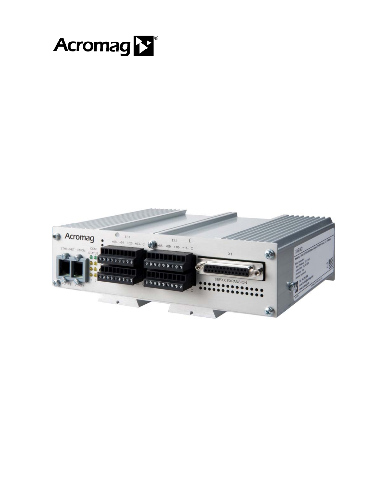
EtherStax™ Stackable Industrial I/O Family
Modbus TCP/UDP/IP 10/100MB Ethernet I/O
Model ES2163 & ES2164
64-Ch Single-Ended Analog Current/Voltage Input
USER’S MANUAL
ACROMAG INCORPORATED Tel: (248) 295-0880
30765 South Wixom Road Fax: (248) 624-9234
Wixom, MI 48393-7037 U.S.A.
Copyright 2009, Acromag, Inc., Printed in the USA.
Data and specifications are subject to change without notice.
8500-825-B10A001

EtherStax™ ES2163/2164 User’s Manual Modbus TCP/UDP/IP Analog Input
__________________________________________________________________
_______________________________________________________________________________________
Acromag, Inc. Tel:248-295-0880 Fax:248-624-9234 Email:sales@acromag.com http://www.acromag.com
2
IMPORTANT SAFETY CONSIDERATIONS
You must consider the possible negative effects of power, component,
wiring, sensor, or software failure in the design of any type of monitoring or
control system. This is very important where property loss or human life is
Involved. It is important that you perform satisfactory overall system design
and it is agreed between you and Acromag, that this is your responsibility.
GETTING STARTED
QUICK START………………………………………….. 3
MOUNTING AND DIMENSIONS……………………… 5
CONTROLS & INDICATORS..………………………… 12
ISOLATION BARRIERS..………………………………. 13
CONNECTIONS…………………………………………. 14
Network…………………………………………….. 14
Redundant Media Connections………………... 21
Power……………………………………………….. 23
Earth Ground..………………………………….…. 23
Alarm Relay………………………………………... 24
Analog Inputs.…………………………………….. 25
Analog Common..………………………………… 26
WEB BROWSER………………………………………... 26
Home Page………………………………………… 26
Password Configuration Page.………………... 27
Network Configuration Page…………………… 27
Input Configuration Page……………………….. 31
Test Page………………………………………….. 37
Calibration Page………………………………….. 38
Utility Page………………………………………… 46
TROUBLESHOOTING………………………………….. 47
Diagnostics Table……………………………..…. 47
Getting Out Of Trouble………………………….. 50
TECHNICAL REFERENCE
KEY FEATURES………………………………………… 51
HOW IT WORKS………….…………………………….. 52
Key Observations…..……………………………. 53
MODBUS REGISTERS………………………………… 54
Register Functions………………………………. 54
Register Mirroring……………………………….. 55
Register Map……………………………………… 57
SPECIFICATIONS………………………………………. 81
Model Numbers….……………………………….. 81
Mounting Options………………………………... 81
Analog Input Specifications…….……………… 82
General Input Specifications…….…………….. 84
Reliability Prediction…………………………….. 85
Alarm Relay Output…………………………….… 86
Memory…………………………………………….. 86
Agency Approvals…..……………………………. 86
Enclosure and Physical…………………………. 87
Environmental…………………………………….. 88
Ethernet Interface………………………………… 89
Controls & Indicators……………………………. 90
CABLES & CONNECTORS..………………………….. 92
TABLE OF
CONTENTS
Symbols on equipment:
Means “Refer to User’s
Manual (this manual) for
additional information”.
The information of this manual
may change without notice.
Acromag makes no warranty
of any kind with regard to this
material, including, but not
limited to, the implied
warranties of merchantability
and fitness for a particular
purpose. Further, Acromag
assumes no responsibility for
any errors that may appear in
this manual and makes no
commitment to update, or
keep current, the information
contained in this manual. No
part of this manual may be
copied or reproduced in any
form without the prior written
consent of Acromag, Inc.
For additional information,
please visit our web site at
www.acromag.com and
download our whitepaper
8500-765, Introduction To
Modbus TCP/IP, or 8500-648,
Introduction to Modbus.
Windows® is a registered
trademark of Microsoft
Corporation.
!

EtherStax™ ES2163/2164 User’s Manual Modbus TCP/UDP/IP Analog Input
___________________________________________________________________
_______________________________________________________________________________________
Acromag, Inc. Tel:248-295-0880 Fax:248-624-9234 Email:sales@acromag.com http://www.acromag.com
3
If you already know the basics of connecting power, connecting a network
cable, and using a web-browser, and you only need some help establishing
communication, here is a brief outline of what you must do to start
communicating with this device right away and where to go for help.
This is a web-enabled Ethernet device that allows you to use your web-
browser to set it up and operate it. All Ethernet devices have a unique IP
address that you are required to know in order to communicate with them
using your web-browser.
What if you do not already know the IP address of the unit?
All Acromag Ethernet devices include an alternate default mode of operation
with a fixed IP address set to 128.1.1.100. Additionally, the user-
programmable IP address that is used outside of default mode is also initially
set to 128.1.1.100 from the factory. If this unit is fresh from the factory, you
can talk to it at this address in either mode.
If your unit is not as shipped from the factory and may have another IP
address set, then…
You need to place the unit in its Default Mode, which allows you to address it
at IP address 128.1.1.100 (http://128.1.1.100).
You place this unit into Default Mode by depressing the toggle switch to the
position marked “DFT” for about 4 seconds (see front figure at right), just
until the yellow STATUS LED (opposite side of unit) starts blinking slowly to
indicate the unit is in the Default Mode. Let go of DFT toggle when Status
LED starts blinking. If you hold it depressed for too long, it will pass back out
of Default Mode.
Try browsing the unit with your web browser address at http://128.1.1.100.
If your unit is in default mode, you should be presented with the home page
(and your Status LED should continue to blink).
If you are using IP address 128.1.1.100, and you still can’t talk to the unit…
You cannot talk to this device at IP address 128.1.1.100 if the Network
Interface Card you are using to connect to this device is set to an IP address
outside of the address domain established by this default address. You
must set the IP address of your network interface to an address like
128.1.1.x, where x is an integer from 1 to 254, except 100 (our default
address). This procedure is covered in document 8500-815 shipped with
your unit. It is also detailed in Application Note 8500-734, which you can
obtain from the CDROM shipped with your unit, or optionally via download
from our web site at www.acromag.com.
You managed to browse to the unit’s Home Page, but now you need to get
to the Network Configuration Page to set your own IP address…
In order to access any of the other web configuration pages, like the Network
Configuration Page, you will need to first enter a Username = User, and
Password = password to gain access (these are the default username and
password settings for all EtherStax models and these entries are case-
sensitive).
QUICK START
Guide to Quickly
Establishing
Communication
2
PORT 1
1RST
DFT
LED Column 2
PORT 2
ETHERNET 10/100M
LED Column 1
COM Port Status
Default Mode
& System Reset
Toggle Switch
Acromag
COM
STAT US
FRONT OF UNIT
+ -
+ -
B
STATUS
RELAY
G
RLY
A
RUN
GND
G
Alm Relay
(RED)
UNIT STATUS LED's
PWR
Op Status
(YELLOW)
BACK OF UNIT
Run/Power
(GREEN)

EtherStax™ ES2163/2164 User’s Manual Modbus TCP/UDP/IP Analog Input
__________________________________________________________________
_______________________________________________________________________________________
Acromag, Inc. Tel:248-295-0880 Fax:248-624-9234 Email:sales@acromag.com http://www.acromag.com
4
Your unit is not as shipped from the factory and you do not know the
Username and Password settings…
If you forget your user name & password, you can always toggle the unit into
default mode via the DFT toggle switch at the front of the unit (hold this
toggle 4 seconds to invoke default mode). In this mode, the password and
username will revert to the original defaults of “User” and “password” (unit
assumes an IP address of 128.1.1.100 in its default mode), allowing you to
re-invoke the Password Configuration Page and change the username and
password settings as required.
If after applying power, your green RUN LED is not solid ON after 25
seconds and is blinking continuously, you need to do the following:
Normally on power-up, the green RUN LED will blink for about 25 seconds
during initialization, then stay ON. But if you powered the unit up without
making your network connection, the green RUN LED will continue to blink.
If RUN continues to blink, first check that your network cable is connected to
the unit and to your PC. If you replaced the network cable after powering-up,
the RUN LED should stop blinking after about 10 seconds once a network
link has been established. Once the link is established, the green RUN LED
should not continue to blink and should stay ON, even if you later remove the
cable while still powered up.
If you have checked your network connections and the green RUN LED
continues to blink…Reset, Restore, Return:
Reset: Try resetting the unit by momentarily depressing the DFT/RST toggle
switch to the RST position. After about 25 seconds, the green RUN LED
should remain ON.
Restore: If you’ve tried resetting the unit and the green RUN LED still
continues to blink, then you may need to follow the procedure for restoring
the EtherStax to its initial configuration. This procedure is located at the end
of the Trouble-Shooting section of this manual under “Getting Out Of
Trouble” on page 50. Note that this is also the procedure used to sanitize
the unit for de-commissioning. You should only do this as a last resort, as
this procedure restores everything to its default state—all holding registers,
network settings, i2o settings, including any calibration you may have
performed.
If you do use restore and want to return the unit to service, the calibration
reference will additionally have to be “restored” separately via the Restore
Factory Voltage Reference Value button of the Input Calibration Page.
Inputs will be calibrated automatically by default, but any manual calibration
you may have done to improve accuracy is lost after restore and may need
to be rechecked.
Return: At this point, if the green RUN LED continues to blink after resetting
and after restoring, then you may need to return the unit for repair.
If you need additional help and you have already reviewed the material in
this manual, please contact the factory.
QUICK START
Guide to Quickly
Establishing
Communication
EtherStax™ ES2163/2164 User’s Manual Modbus TCP/UDP/IP Analog Input
___________________________________________________________________
_______________________________________________________________________________________
Acromag, Inc. Tel:248-295-0880 Fax:248-624-9234 Email:sales@acromag.com http://www.acromag.com
5
ESA-DIN-VMK TOP VIEW
NOTE: ESA-DIN-VMK CONTAINS
TWO OF THESE PIECES.
ESA-DIN-VMK SIDE VIEW
7.625
GROUND
SCREW
8.226
2.444
6.125
GROUND
SCREW
GROUND
SCREW
DIMENSIONS ARE IN INCHES.
THE ES2163/2164 IS SHOWN AT LEFT.
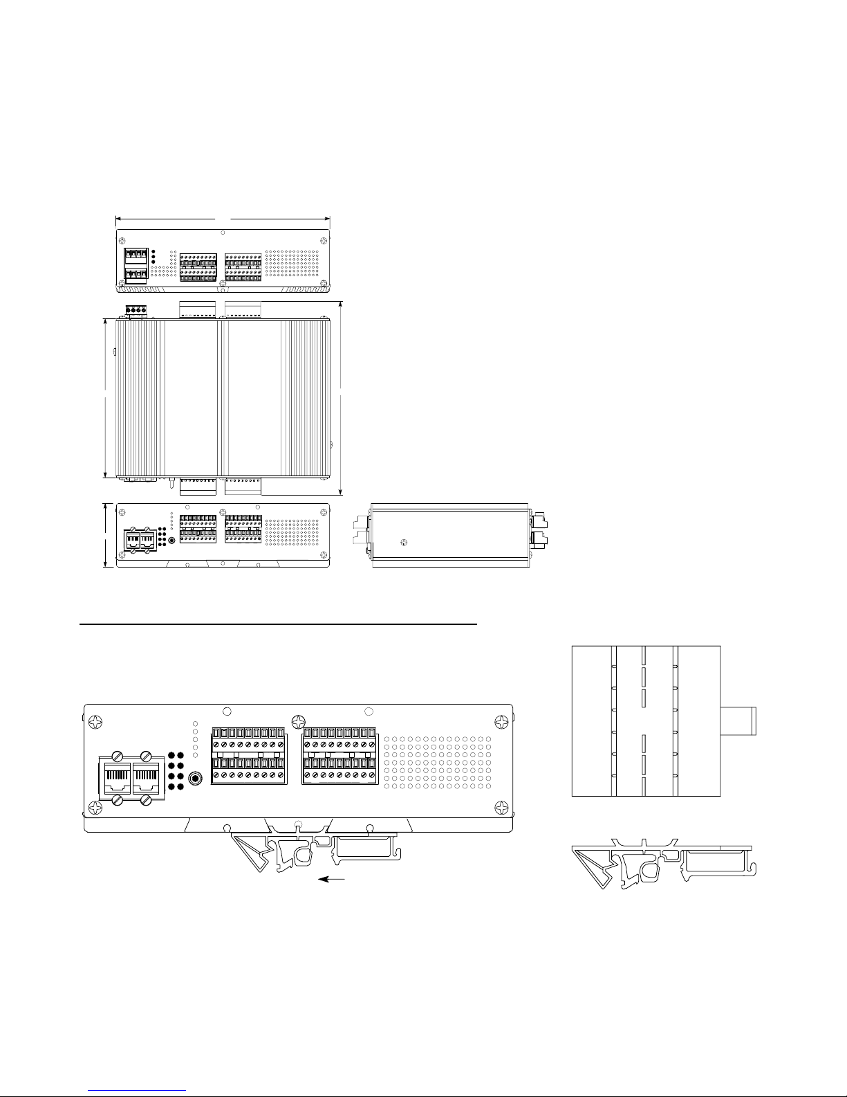
ETHERSTAX DIMENSIONS
A SINGLE UNIT STANDS 2.444 INCHES TALL.
EACH ADDITIONAL UNIT ADDS 2.229 INCHES.
A TWO UNIT STACK IS 4.673 TALL.
A THREE UNIT STACK IS 6.902 TALL.
THE OPTIONAL SURFACE-MOUNT BASE-PLATE
ESA-SMK ADDS 0.25" TO HEIGHT.
THE OPTIONAL DIN RAIL CLIP ESA-DIN-VMK
ADDS 1.0" TO HEIGHT WHEN MOUNTED ON
35mm x15mm DIN RAIL.
THE OPTIONAL BASEPLATE AND HEAVY DUTY
DIN RAIL MOUNT ESA-DIN-HMK ADDS 0.84" TO
HEIGHT WHEN MOUNTED ON 35mm x15mm DIN RAIL.
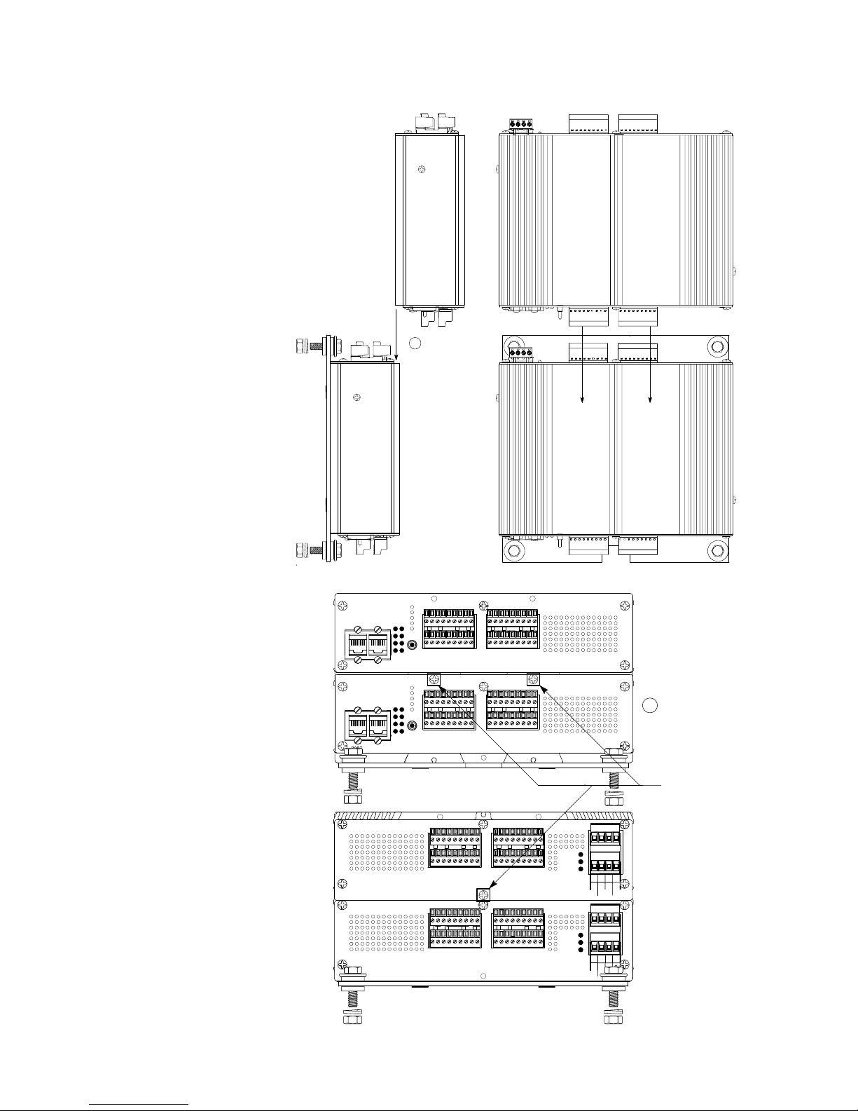
Units are designed to interlock and stack together up to three units high. A
stack of units can be bolted to a wall or flat surface, or mounted on deep-
channel, “T” type, 35mm x15mm DIN rails (per DIN EN60715 TH35),
depending on the optional mounting kit selected. Available mounting kits are
shown below.
DIN Rail Vertical Mount Kit ESA-DIN-VMK (One or Two Units):This kit
includes two plastic DIN clips (Rose Bopla #77003500) that slide into the
dove-tail channel of the bottom of the housing. You can use one clip to
mount a single unit, or both for added stability when stacking two units. If
stacking more than two units on a DIN rail, see ESA-DIN-HMK.
08 10 12
TS1
14 C 24 26 28 30 C
1 2
00 02 04 06 C 16 18 20 22 C
PORT 1
PORT 2
RST 09 11 13 15 25 27 29
TS2
31
DFT
01
TOP
03 05 07 17 19 21 23
STATUS
ETHERNET 10/100M
TOP should coincide with
the upper lip of the DIN rail
This side of clip should
align with top of rail
COM
UPWARD
Position clip such that TOP is aligned
with end of unit you want upright.
Acromag
DIN MTG CLIP
OF ESA-DIN-VMK
TO REMOVE: Push unit upward and tilt TOP of
unit back towards you to disengage it from rail.
TO HANG: Tilt unit and place TOP of clip over upper lip
of DIN rail. Press bottom towards rail to snap in place.
MOUNTING AND
DIMENSIONS
These Models are open-type
devices and intended for
installation into a suitable
enclosure by the end-user.
It is recommended that
enclosed units be panel-
mounted with the vented
endplates positioned at top
and bottom for improved
cooling. Review the Operating
Ambient Temperature
specification for more
information.
A single unit stands 2.444
inches tall. Each additional
unit adds 2.229 inches.
A two-unit stack would be
4.673 inches tall. A three unit
stack is 6.902 inches tall. Add
any additional height as
necessary to account for the
mounting plate, DIN clip, and
DIN rail, if required.

EtherStax™ ES2163/2164 User’s Manual Modbus TCP/UDP/IP Analog Input
__________________________________________________________________
_______________________________________________________________________________________
Acromag, Inc. Tel:248-295-0880 Fax:248-624-9234 Email:sales@acromag.com http://www.acromag.com
6
USE A DIN RAIL STOP TO
PREVENT MOVEMENT
(Example: IDEC BNL-5)
NOT INCLUDED
Note: Position of stop not
exactly as shown.
UNIT IS SHOWN
MOUNTED USING
BOTH CLIPS OF
ESA-DIN-VMK KIT.
35mm x15mm DIN RAIL
(Example: IBOCO OMEGA 3AF)
VERTICAL DIN-RAIL MOUNT
USING ESA-DIN-VMK
Simply slide the clips of this kit into the dovetail channel at the bottom of the
enclosure. You can use one clip, or both (recommended) DIN clips of this
kit to mount a single unit. For a stack of two units, both clips must be used.
To remove a unit from the DIN rail, you have to lift the assembly upward and
tilt the top of the unit back to disengage it from the rail. If you choose to
install both DIN clips for added security (recommended), then more pressure
will be required to disengage the unit from the rail. To mount a stack of 3
units to a DIN rail, use the heavy-duty DIN kit model ESA-DIN-HMK instead.
TOP
35mm x15mm
DIN RAIL
IMPORTANT: Stack no more than 2 units with ESA-DIN-VMK.
Use both clips of this kit with two units stacked together.
ETHERSTAX MOUNTING WITH ESA-DIN-VMK
MOUNTING AND
DIMENSIONS
The drawing at right shows
how to mount a unit with the
ESA-DIN-VMK kit.
This kit includes two DIN clips
for added stability, or for
mounting a stack of two units.
Note the orientation of the DIN
clips relative to the rail.
To remove a unit from the rail,
grip unit on each side and
pull/push upward, while tilting
the top back to release the unit
from the upper lip of the DIN
rail.
You can use the ESA-DIN-
VMK to mount a unit
horizontally, or vertically as
shown at right. Be sure to use
a DIN rail stop to prevent the
unit from moving along the rail
with vertically mounted DIN
rail.
Note that enclosed units
oriented as shown at right will
have improved cooling ability
(see Operating Ambient
Temperature).
EtherStax™ ES2163/2164 User’s Manual Modbus TCP/UDP/IP Analog Input
___________________________________________________________________
_______________________________________________________________________________________
Acromag, Inc. Tel:248-295-0880 Fax:248-624-9234 Email:sales@acromag.com http://www.acromag.com
7
5.368
2.986
6.675
0.375
1.923
0.400"
TYP
2.250
0.625
4.250
0.25
TYP
0.400"
TYP
OPEN BOARD
MTG HOLES
0.160 DIA
(4 PLACES)
4.709
1.875
1.980
0.125
4.00
RUBBER
GROMMET
COUNTER-SINK THIS
SIDE (4 PLACES)
5.750
ESA-SMK SIDE VIEW
3.500
3.291
1.000
ESA-SMK TOP VIEW
8.000
RUBBER
GROMMET
2.000
8.000
ENCL MOUNT
0.250 DIA HOLE w/
0.500 DIA x 100 DEG
COUNTER-SINK ON
BOTTOM SIDE
(4 PLACES)
NOTCH FOR
DIN LATCH
0.266 I.D. x 0.625 O.D. GROMMET
IN 0.406 HOLE (4 PLACES)
NOTE VERTICAL OFFSET
OF THIS HOLE COMPARED
TO HOLE AT RIGHT SIDE
DIN MOUNT
0.089 DIA FOR 4-40
TAP (7 PLACES)
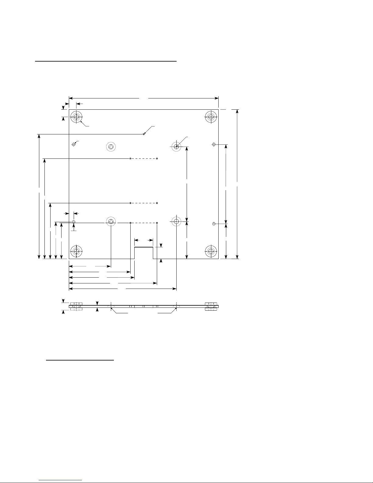
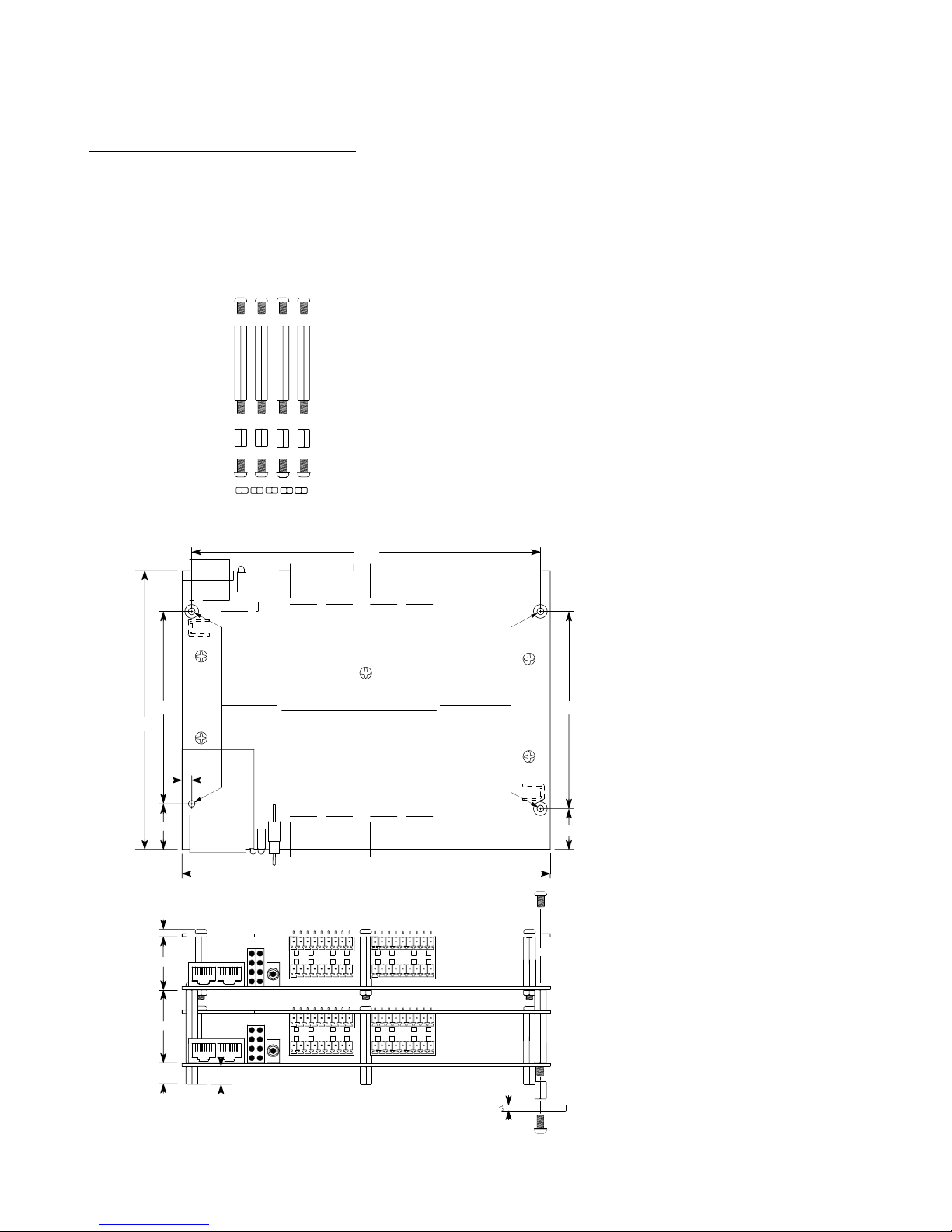
Surface-Mount Kit ESA-SMK (One to Three units):This kit includes a
shock-mounted aluminum base-plate and bolts that attach to the bottom of
the housing. Mounting holes with rubber grommets at each corner support
¼-inch bolts for mounting to flat surfaces. Up to three units may be stacked
on this plate.
This plate also includes the four holes necessary for mounting an open-
frame circuit board to it (i.e. no enclosure with hardware of ESA-OMK).
ESA-SMK Kit Contents:
1 Pre-Drilled Aluminum Base-Plate, 8 x 8 x 0.125.
4 ¼-20 x 0.375 Flat-Head, 100° Counter-Sink, Phillips
4 Rubber Grommet, 0.625 O.D. x 0.266 I.D.
The ¼-inch bolts and washers recommended to attach this assembly to
a flat surface or panel are not provided.
For DIN rail mounting of this plate, see ESA-DIN-HMK
MOUNTING AND
DIMENSIONS
Insert the four rubber
grommets into the holes at
each corner of the base-plate.
Then use the four ¼-20x0.375,
flat head, counter-sink bolts
provided to bolt this plate to
the bottom of the enclosure.
Be sure to insert the bolts from
the counter-sink side of the
plate.
Add any additional units to
your stack–you can safely
stack up to three units on this
plate.
Use ¼-inch bolts (not
provided) to bolt this assembly
to a wall or flat surface. It is
further recommended that flat
washers (not provided) be
used to protect the rubber
grommet.
EtherStax™ ES2163/2164 User’s Manual Modbus TCP/UDP/IP Analog Input
__________________________________________________________________
_______________________________________________________________________________________
Acromag, Inc. Tel:248-295-0880 Fax:248-624-9234 Email:sales@acromag.com http://www.acromag.com
8
1
2
3
Bolt to wall or flat surface using
1/4 bolts (not provided) at each
corner. Use a flat washer at the
grommet interface as shown.
You will have to temporarily
unplug terminal blocks to
insert bolts through grommet.
Insert rubber grommet
provided into holes at
each corner of baseplate. FLAT WASHER REQUIRED, 4 PLACES (NOT INCLUDED)
ETHERSTAX SURFACE MOUNTING WITH ESA-SMK
Attach baseplate to
enclosure using four
1/4-20 flat-head bolts
provided. Insert bolts
through counter-sink
side of baseplate.
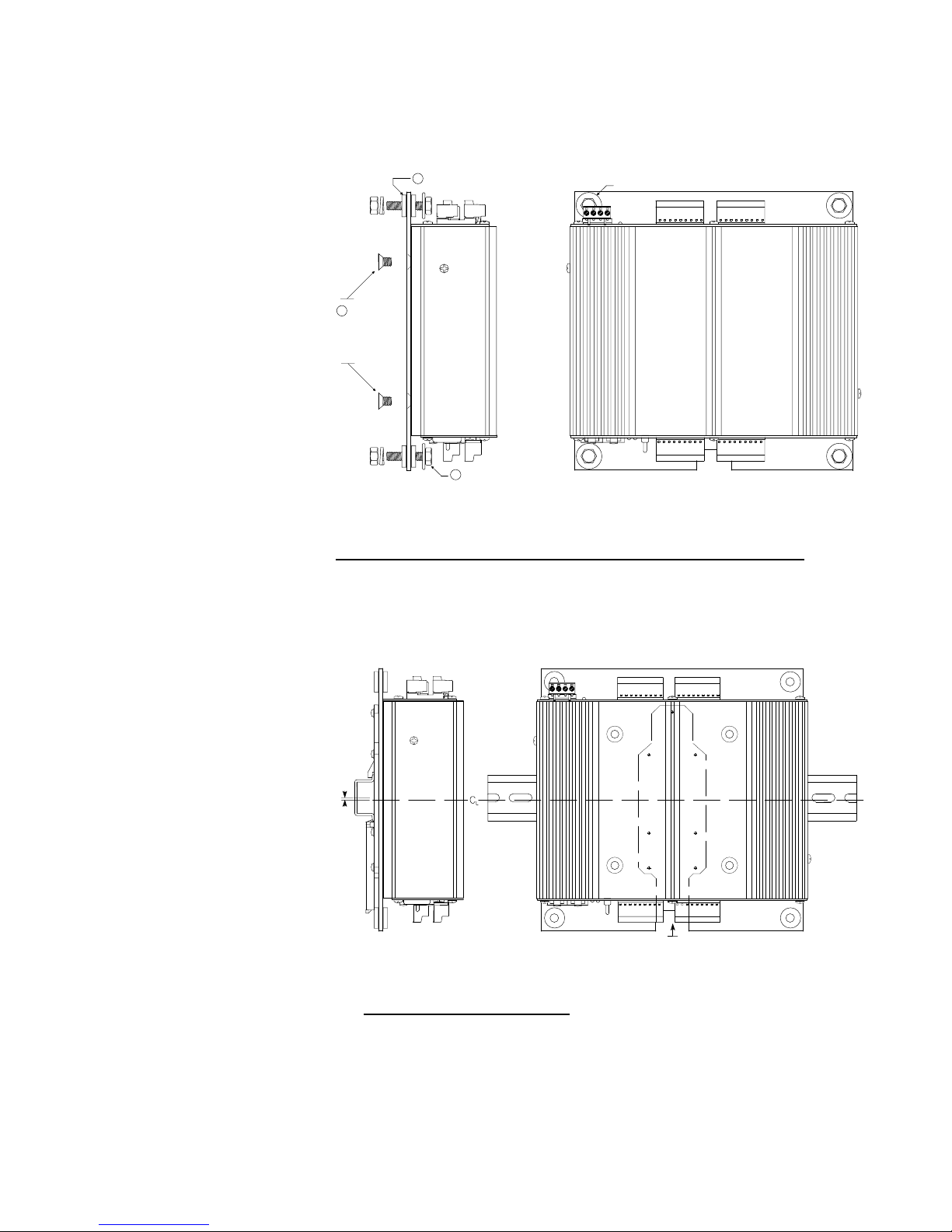
DIN Rail Horizontal Mount Kit ESA-DIN-HMK (one to three units):This
kit has the same base-plate as ESA-SMK above, but adds a heavy-duty DIN
adapter (Phoenix UTA-159), and screws for mounting to 35x15mm T-type
DIN rails. Up to three units may be stacked on this plate and mounted to a
DIN rail.
0.10"
35mm x15mm
DIN RAIL
NOTCH FOR ACCESS TO
DIN CLIP RELEASE TAB
(Insert screwdriver here to
pry back spring clamp and
release unit from rail)
ETHERSTAX MOUNTING WITH ESA-DIN-HMK
ESA-DIN-HMK Kit Contents:
1 Pre-Drilled Aluminum Base-Plate, 8 x 8 x 0.125.
4 ¼-20 x 0.375 Flat-Head, 100° Counter-Sink
4 Rubber Grommet, 0.625 O.D. x 0.266 I.D.
1 Heavy-Duty DIN Adaptor (Phoenix UTA-159)
7 4-40 x 0.25 screw with lock-washer
MOUNTING AND
DIMENSIONS
This is the recommended
mounting orientation for
reducing internal heat
generation (see Ambient
Operating Temperature at the
back of this manual).

EtherStax™ ES2163/2164 User’s Manual Modbus TCP/UDP/IP Analog Input
___________________________________________________________________
_______________________________________________________________________________________
Acromag, Inc. Tel:248-295-0880 Fax:248-624-9234 Email:sales@acromag.com http://www.acromag.com
9
0.84" 2.44" 2.29"
7.74"
2.29"
3.28"
5.51"
0.25"
35mm x15mm
DIN RAIL
SUBTRACT 0.59" FROM DIMENSIONS SHOWN IF USING
ESA-SMK BASE-PLATE (NO DIN RAIL MOUNT).
UP TO 3 UNITS MAY BE STACKED ON A DIN RAIL USING ESA-DIN-HMK AS SHOWN.
ETHERSTAX ESA-DIN-HMK STACKING
To attach or remove the ESA-DIN-HMK to/from the DIN Rail, use a
screwdriver tip inserted into the slot at the end of the DIN clip, in the area of
the notch of the base-plate as shown below. Pry back to compress the DIN
clip spring, then release it from the rail. You may have to temporarily unplug
the terminal blocks in the area of this notch to gain access to the DIN clip.
09 11 13 15 25 27 29 31
21
01 03 0 076 C 17 19 21 23
PORT 2
DFT
08 10 12 14
TS1
24 26 C28 30
TS2
RST
COM
STATUS
00 02 04 16 18 C20 22
PORT 1
ETHERNET 10/100M
LOCATE DIN LATCH IN AREA OF NOTCH IN BASE-PLATE
35mm x15mm
DIN RAIL
ETHERSTAX ESA-DIN-HMK
REMOVAL FROM DIN RAIL
Acromag
USE A SCREWDRIVER AS SHOWN TO PRY BACK
ON DIN RAIL LATCH AND RELEASE UNIT FROM RAIL.
IT MAY BE NECESSARY TO TEMPORARILY UNPLUG
TERMINAL BLOCKS TO GAIN ACCESS TO DIN LATCH.
MOUNTING AND
DIMENSIONS
IMPORTANT: Be sure to
remove power before
attempting to disengage unit
from the DIN rail.
Be sure to grip unit firmly
before disengaging unit from
rail and avoid dropping it.
Note that you can stack up to
3 units on the ESA-DIN-HMK
or ESA-SMK as shown at left.
Subtract 0.59 inches from
dimensions shown if using
ESA-SMK (i.e. no DIN rail
mount).
EtherStax™ ES2163/2164 User’s Manual Modbus TCP/UDP/IP Analog Input
__________________________________________________________________
_______________________________________________________________________________________
Acromag, Inc. Tel:248-295-0880 Fax:248-624-9234 Email:sales@acromag.com http://www.acromag.com
10
1
UPPER UNIT
RESTS ON FRONT
PLATE OF LOWER
UNIT
SLIDE UNITS
TOGETHER
SLIDE UPPER UNIT INTO
DOVETAIL CHANNEL OF
LOWER UNIT UNTIL IT
RESTS UPON FRONT
ENDPLATE.
SECURE UNITS
TOGETHER VIA TWO
6-32 SCREWS AT
FRONT, AND ONE
6-32 SCREW AT
CENTER OF REAR
ENDPLATE.
BUILDING A STACK
2
21
40
32
09
01
42
42
34
11
03
44
36
13
05
45
37 38
15
07
C47
C
39 C
C
C
56
48
25
17
58
50
27
19
60
TS4
52
29
21
62
54
31
23
C
C
RLY
B
A
+-
+-G
21
32
40
09
01
34
11
03
36
44
13
05
37 38
45 46
15
07
C39
47
C
C
O
U
T
P
U
T
S
O
U
T
P
U
T
S
56
48
25
17
58
50
27
19
TS4
60
52
29
21
62
54
31
23
C
C
A
B
RLY
+-
+-
G
G
PORT 1
COM
STATUS
41 43
43
33 35
10 1208
00 02 04
46
14 24
06 16
57 59 61 63
55535149
C26 28 30
C18 20 22
TS2
STATUS
RELAY
RUN
COM
STATUS
PORT 1
33 35
41
08 10 12
02 0400
14 24
06 16
57 59 61 63
55535149
C26 28 30
TS2
C18 20 22
RUN
STATUS
RELAY
PWR GND
2
RSTRST
ETHERNET 10/100M
TS3
TS1
ETHERNET 10/100M
DFT
PORT 2
RST
Acromag
RST
DFT
TS3
REAR VIEW
TS1
Acromag
SECURE UNITS
TOGETHER VIA TWO
6-32 SCREWS AT
FRONT AS SHOWN,
AND ONE 6-32 SCREW
AT CENTER OF REAR
ENDPLATE.
FASTEN UNITS
TOGETHER w/
3 SCREWS AS
SHOWN
MOUNTING AND
DIMENSIONS
The drawing at right shows
how to stack units together.
You can stack up to three units
together in this manner.
WARNING: Be sure to grip
the edges of unit firmly when
stacking units and avoid
dropping it.
EtherStax™ ES2163/2164 User’s Manual Modbus TCP/UDP/IP Analog Input
___________________________________________________________________
_______________________________________________________________________________________
Acromag, Inc. Tel:248-295-0880 Fax:248-624-9234 Email:sales@acromag.com http://www.acromag.com
11
6-32 NUT
(NYLON)
BOTTOM
STANDOFF
MTG PLATE
SCREW
TOP BOARD
SCREW
BD-TO-BD
STANDOFF
#5 6-32 NYLON NUT, REPLACES
STANDOFF OF UPPER BOARD
ESA-OMK kit items are also included with every open board assembly.
#4 1/4-HEX FEMALE STANDOFF
3/8 LONG w/6-32 THREADS
#4 6-32x0.25 PAN HEAD SCREWS
ESA-OMK KIT CONTENTS
#4 6-32 x0.25 SEMS SCREW
WITH INTEGRATED WASHER
#4 1/4-HEX MALE-FEMALE STANDOFF
1-9/16 LONG WITH
6-32 x0.375 FEMALE THREAD &
6-32 x0.250 MALE THREAD
0.440
1.139
0.980
4.145
0.25
TYP
0.125
1.563
0.375
0.150
6.000
MTG PLATE
(ESA-SMK)
7.920
STANDOFF MOUNTING - 4 PLACES
7.500
0.875
4.250
DIMENSIONS ARE IN INCHES
(FOUR 0.150 DIA MOUNTING HOLES
WITH 0.280 DIAMETER SHOULDER
AND 0.108 ISOLATION CLEARANCE)
OPEN STACK ASSEMBLY (TWO DUO UNITS)
ETHERSTAX DUAL BOARD
OPEN FRAME DIMENSIONS
Open-Board Mounting Kit ESA-OMK:EtherStax units can be ordered and
mounted without their enclosure. This kit includes the jack-screws, and
fasteners necessary to stack two open circuit boards together (or two dual
board assemblies), plus the standoffs and screws for mounting this
assembly to a flat surface. Note that this is also a replacement kit, as open-
frame units already include these items (except for 6-32 nuts). Use
additional kits as required for stacking more than two boards in this manner.
MOUNTING AND
DIMENSIONS
IMPORTANT: Units ordered
without their enclosure do not
retain safety agency listing, but
are recognized components
(see Specifications – Agency
Approvals). Open-frame units
are also vulnerable with
respect to ESD. While the
open unit retains all of its built-
in transient suppression and
filtering, the sensitive
electronic circuits are left
exposed to ESD damage
without the protection of an
enclosure.
You should take adequate
measures to protect open-
frame mounted units from
dust, debris, and ESD.
Thus, it is recommended that
open units be mounted in a
protective enclosure or
cabinet.
Note: Open-frame units may
also mount to the optional
surface-mounted base plate
ESA-SMK to facilitate surface
or DIN-rail mounting. This
plate has mounting holes
located as shown to mate with
those of the circuit board.
Be very careful when handling
open-frame circuits to avoid
ESD damage to sensitive
circuit components.

EtherStax™ ES2163/2164 User’s Manual Modbus TCP/UDP/IP Analog Input
__________________________________________________________________
_______________________________________________________________________________________
Acromag, Inc. Tel:248-295-0880 Fax:248-624-9234 Email:sales@acromag.com http://www.acromag.com
12
DFT
08
I
09 10 11 13 15 24 26 28 30 C
Rx
Tx 2RST
00 02 04 05 07 16 18 20 22 C
10/100 T/TX
ETHERNET
STATUS
V
12 14
TS1
C25 27
I
V
29 31
100 FX
PORT 2
1
01 03 06 C171921 23
NETWORK PORTS
100 FX
TS2
10/100 T/TX
PORT 1
Acromag
ES2163-1XXX FRONT-PANEL
(w/ SC-TYPE FIBER PORT 1)
ES2164-1XXX IS IDENTICAL
INPUT PORT 2
(CH16-CH31)
COMMUNICATION STATUS INDICATORS
DEFAULT/RESET TOGGLE SWITCH
INPUT PORT 1
(CH00-CH15)
09
01
11
03
13
05
15
07
24
16
26
18
28
20
30
22
C31
C23
2
DFT
RST
08 10 12 14
00 02 04 06
TS 1
C25 27
C1719
29
21
PORT2
1
COM
STATUS
TS 2
PORT1
NETWORK PORTS
ETHE RNE T 10/100M
Acromag
(10/100MEthernet)
ES2163-0XXX FRONT-PANEL
(ES2164-0XXX IS IDENTICAL)
INPUT PORT 2
(CH16-CH31)
COMMUNICAT ION STAT US INDICAT ORS
DEFAULT / RE SE T T OGGLE SWI T CH
INPUT PORT 1
(CH00-CH15)
Cable Termination Kit ESA-CTK: The EtherStax enclosure includes a
panel mounted frame around the RJ45 network port that accommodates
special IP20 clip-type plug connectors that help to secure network
connections from shock and vibration. You can still utilize standard RJ45
modular plug connectors, but if you want the added security of this clip
frame, then you have to use the compatible cable plug connectors provided
by this kit. This kit provides the male plug and sleeve housing for one end of
Category 5 Ethernet cable that will mate to this frame. Category 5 cable is
not included. You will also require a modular crimping tool for attaching the
plug to your cable (most standard RJ45 crimping tools will work).
Units ordered without their enclosure cannot utilize this clip.
MOUNTING AND
DIMENSIONS
CONTROLS &
INDICATORS
Front Panel
Two columns of status
indicators for the network ports
are used to indicate different
things according to whether
the unit is in switch mode, or
hub/repeater mode. Refer to
Specifications – Controls &
Indicators for these definitions.
The toggle switch is used to
toggle the unit into or out of
Default Mode (toggle up & hold
4 seconds), or to reset the unit
(toggle down).
In Default Communication
Mode, the yellow STATUS
LED on the back of the unit will
flash slowly and the unit will
assume a fixed static IP
address of “128.1.1.100”, a
default subnet mask of
“255.255.255.0”, a default
username of “User”, and a
default password of
“password”.
RJ45 PLUG
IP20 SLEEVE
HOUSING
CAT5 CABLE
(NOT INCLUDED)
CLAMPS TO FRAME
OF ETHERSTAX
HOUSING
ESA-CTK IP20 CAT5
CABLE TERMINATION KIT

EtherStax™ ES2163/2164 User’s Manual Modbus TCP/UDP/IP Analog Input
___________________________________________________________________
_______________________________________________________________________________________
Acromag, Inc. Tel:248-295-0880 Fax:248-624-9234 Email:sales@acromag.com http://www.acromag.com
13
40 42 44 46 C 57 59 60 61 62 C
GND
32 34 36 38 C 49 51 53 54 55 C
B
A
-
-
G
G
41 43 45 47 56 58 63 RUN
STATUS
PWR
TS3
33 35 37 39 48 50
TS4
52
RELAY
+
+
RLY
ES2163-0XXX BACK-PANEL
(ES2164-0XXX IS IDENTICAL)
INPUT PORT 4
(CH48-CH63)
The Earth Ground (G) terminals are common
to the enclosure and isolated from I/O, power,
and relay connections.
ES2163 INPUTS ARE CURRENT, ES2164 INPUTS ARE VOLTAGE UNIT INDICATORS -
Alarm (Red), Status
(Yellow), and Run
(Green).
POWER/
EARTH GROUND/
RELAY CONNECTIONS
INPUT PORT 3
(CH32-CH47)
RELAY
Port 1
GROUND
POWER
NETWORK
Port 2
GROUND
SCREW
GROUND
SCREW
INPUT CIRCUITRY INPUT PORTS SHARE ANALOG COMMON.
CONNECT PORT COMMON (C) TO EARTH GROUND.
MODEL ES216x ISOLATION DIAGRAM
(Dashed Lines Denote Isolation Barriers)
INPUT CIRCUITRY INPUT PORTS SHARE ANALOG COMMON.
CONNECT PORT COMMON (C) TO EARTH GROUND.
NOTE: The Ground (G) terminals are
common to the enclosure and isolated
from the power, relay, inputs, and network
circuits for safety and noise immunity.
CONTROLS &
INDICATORS
Back Panel
The Green RUN LED (bottom)
is ON if power is on and will
blink in “wink” ID mode.
The Yellow STATUS LED
(middle) blinks ON/OFF slowly
in default communication
mode and blinks rapidly if a
watchdog timeout has
occurred.
The Red RELAY LED (top) is
ON if relay is energized (relay
terminals A & B are closed).
ISOLATION BARRIERS
Dashed Lines denote isolation
barriers. Additionally, the
enclosure is also isolated.
The input circuitry, network
ports (each), power circuit,
relay, and enclosure (earth
ground) are isolated from each
other for safety and noise
immunity.
Note that the network ports are
individually isolated from the
rest of the circuit and from
each other.
IMPORTANT: Transient
suppression devices are
internally shunted to earth
ground, please connect the
ground terminal to a suitable
earth ground to complete this
path and protect the unit.
Ground may alternately
connect to the ground screw
on either side of the unit
instead of the ground terminal.
EtherStax™ ES2163/2164 User’s Manual Modbus TCP/UDP/IP Analog Input
__________________________________________________________________
_______________________________________________________________________________________
Acromag, Inc. Tel:248-295-0880 Fax:248-624-9234 Email:sales@acromag.com http://www.acromag.com
14
1 2 RST
PORT 2
DFT
COM
STATUS
PORT 1
ETHERNET 10/100M
FRONT OF UNIT
Acromag
The RJ45 clip frame mates with the compatible
connectors of the ESA-CTK for increased
immunity to shock & vibration.
RJ45 Clip Frame
for secure media
connections.
For Compatible
Connectors, see
ESA-CTK Cable
Termination Kit
8
8
CLIP
8
5
6
2
3
PIN
CABLE
1
1
7
4
1
100M
SPEED DISTANCE
10Base-T
Not Used
Not Used
Receive -
Transmit -
Receive +
MDI WIRING
100M100Base-TX
RECOMMENDED CABLE
Not Used
Not Used
Transmit + ETHERNET PORT
CAT 3, CAT 4, or CAT 5 UTP
Not Used RJ-45 CONNECTOR
Not Used
Transmit -
Receive -
Transmit +
MDI-X WIRING
CAT 5/5e UTP/STP
Not Used
Not Used
Receive +
Note Crossover Connections
RJ45 MDI AND MDI-X CONNECTIONS
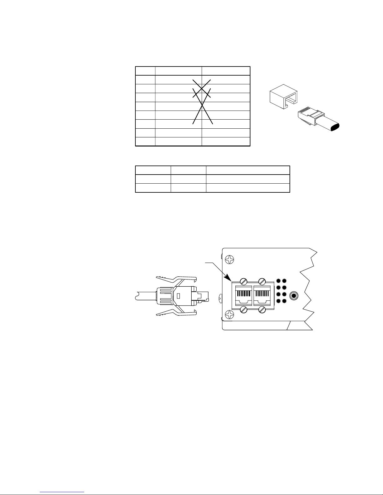
The Ethernet port of this unit is wired MDI-X by default, but includes
automatic crossover (the Ethernet port of your PC is typically wired MDI).
Thus, you can use either a straight-through or crossover cable to connect
this device directly to a PC, Ethernet switch, or another unit.
For increased immunity to shock and vibration, the RJ45 network
connections include special clip frames that can be used with compatible
plug connectors to help secure your network connection from breaking free
under shock or vibration. You can still utilize industry standard RJ45
modular plugs, but if you want the extra security provided by this clip frame,
then you can order compatible connectors via the Acromag ESA-CTK Cable
Termination Kit. This kit includes the male plug and sleeve housing that
mate to the RJ45 frame of the enclosure for one end of CAT5 cable (cable
not included). You will also need a modular plug crimping tool for attaching
the plug provided to your cable.
CONNECTIONS
Network
For 100Base-TX systems, at a
minimum, use data grade
Unshielded Twisted-Pair
(UTP) wiring that has a 100
characteristic impedance and
meets the EIA/TIA Category 5
wire specifications.
It is recommended that you
use a CAT-5 cable to connect
this device to your PC.
For 10Base-T systems, you
may use Category 3, Category
4, or Category 5/5E UTP/STP
cable.
In either case, you are limited
to 100 meters between any
two devices.
For compatible male plug
connectors, order the Cable
Termination Kit, Acromag
ESA-CTK.

EtherStax™ ES2163/2164 User’s Manual Modbus TCP/UDP/IP Analog Input
___________________________________________________________________
_______________________________________________________________________________________
Acromag, Inc. Tel:248-295-0880 Fax:248-624-9234 Email:sales@acromag.com http://www.acromag.com
15
Rx
100 FX
Tx
09
01
11
03
13
05
15
07
25
17
27
19
29
21
31
23
2RST
DFT
08
00
10 12 14 C
02 04 06 C
TS1
24 26 28
16 18 20
TS2
30 C
C22
PORT 2 PORT 1
ETHERNET 10/100M
1
COM
STATUS
Acromag
(Use Regular or
Crossover Cable)
Connect to
Network
Port 1 or 2
CAT-5 UTP CABLE
UP TO 100 METERS
HOST PC
Host PC w/ Network Interface Card (NIC)
Note: This MDI to MDI-X connection does not require a crossover cable.
HOST PC CONNECTED DIRECTLY TO UNIT
If your unit is a Model ES2163/2164-1xxx, it includes both a 100FX fiber port
and a 10BT/100BTX copper port. To connect directly to the fiber port from
your PC, you will need a compatible NIC card installed in your PC, or a
media converter. Note that the auto-crossing feature does not apply to fiber
connections and the Tx and Rx fiber channels must be mechanically
crossed.
Optionally, you may use an external Ethernet switch to connect to your
EtherStax unit (recommended). The recommended approach for switched
Ethernet is to connect one unit or Ethernet device per switch port. This is
the most efficient and deterministic method of communication as it increases
network throughput and eliminates data collisions.
The next section reviews the operation of Ethernet hubs and switches as it
relates to the built-in Ethernet switch of this device, which may optionally
operate as an Ethernet hub/repeater. You can skip the next two pages if you
are already familiar with these terms.
1
COM
STATUS
LED Column 1 - Port 1
LED Column 2 - Port 2
1=LED of Column 1
2=LED of Column 2
2
SWITCH MODE
YELLOW
YELLOW
GREEN No Function in Switch Mode.
1=Port 1 Link/Activity, 2=Error at Port 1.
1=Port 2 Link/Activity, 2=Error at Port 2.
1=Hub Activity, 2=Hub Collision.
YELLOW 1=MII/CPU Link/Activity, 2=MII/CPU Error.
HUB/REPEATER MODE
Speed - ON for 100Mbps, OFF for 10Mbps.
Full-Duplex/Collision - ON for Full-Duplex, Blinks for Half-
Duplex Collisions, OFF for Half-Duplex and No Collisions.
Refer to Specifications - Controls & Indicators Section for more detail.
Link/Activity - ON if Linked/Blinks if Activity.
CONNECTIONS
Network – Basic
Connections
Your host PC will require that
a 10/100M network interface
card (NIC) for Ethernet be
installed to connect to the
EtherStax unit. You may
connect to port 1 or port 2 of
the EtherStax. The EtherStax
unit is auto-crossing, allowing
you to use a regular or
crossover cable to make
connections.
IMPORTANT (Fiber Models):
Some models will substitute an
SC-type fiber port connector
for port 1. The auto-crossing
feature of these units does not
apply to the fiber connection
and transmit must be manually
crossed over to receive, and
visa-versa. Facing the front
end-plate of the unit, the
Transmit (Tx) channel is the
bottom half of the SC style
connector, while the top half is
Receive (Rx).

EtherStax™ ES2163/2164 User’s Manual Modbus TCP/UDP/IP Analog Input
__________________________________________________________________
_______________________________________________________________________________________
Acromag, Inc. Tel:248-295-0880 Fax:248-624-9234 Email:sales@acromag.com http://www.acromag.com
16
This device has a built-in Ethernet switch that can alternately operate as an
Ethernet hub. To understand which mode to use and how to network
connect Ethernet devices, you need to review switch operation and the
differences between a switch and a hub. If you are already familiar with
these terms, skip over this information and review the various network
connections examples outlined in the following pages.
An Ethernet hub (or repeater) is a device that simply connects Ethernet
nodes. Any message at one hub port is repeated on all ports. That is, hubs
forward data packets they receive from a single station to all hub ports. As a
result, all port devices connected to a single hub will share the same
bandwidth. Then as nodes are added to the network hub, they compete for
this finite amount of bandwidth (at 10Mbps or 100Mbps). This can cause
data collisions to occur and makes network determinism impossible,
particularly on busy networks. Determinism is a term that is used to
describe the ability to guarantee that a packet is sent or received in a finite
and predictable amount of time. In the past, lack of determinism is the main
reason that Ethernet has had problems being accepted for use in critical
control applications, as most control systems have a defined time
requirement for packet transmission, typically less than 100ms.
An Ethernet switch (or switching hub) is an intelligent device that is used to
more efficiently connect distributed Ethernet nodes than a hub. Unlike a
simple hub, a switch provides targeted data transfer, as it will forward a data
packet to a specific port or network segment, rather than all ports, thus
freeing up bandwidth. The ability to target a packet to a specific port
increases network throughput and helps to eliminate the collisions that
historically make Ethernet non-deterministic.
•Switches act as intelligent repeaters to increase network distance.
•Switches split networks into separate collision domains at each port.
•Switches provide determinism by reducing collisions.
•Switches increase network bandwidth/throughput.
•Switches can provide supplemental error checking.
With Ethernet, any device can try to send a data frame at any time. The
arbitration protocol for carrier transmission access of the Ethernet network is
called Carrier Sense Multiple Access with Collision Detect (CSMA/CD). If
two devices happen to send a data frame at the same time, then a collision
may occur. With CSMA/CD, each device will first sense whether the line is
idle and available for use. If it is, the device will begin to transmit its first
frame. If another device also tries to send a frame at the same time, then a
collision occurs and both frames are discarded. Each device then waits a
random amount of time and retries its transmission until it is successfully
sent.
Unlike other Ethernet devices, such as an Ethernet host adapter or Network
Interface Card (NIC), the port of a switch does not require its own MAC
address. During retransmission of a received packet, the switch port will
instead look like the originating device by having assumed its source
address. This is why the Ethernet collision domain is said to terminate at the
switch port. That is, a two-port switch will effectively break a network into
two distinct data links or segments (also called collision domains). Since all
Ethernet nodes are able to recognize the occurrence of a collision, and since
the detection of a collision is principal to the way Ethernet arbitrates media
access, large domains containing many nodes can become cumbersome.
CONNECTIONS
Network – Background
Hubs & Switches
To properly network connect
this device, you need to know
a little bit about network hubs
and switches. Please take a
moment to review this material
before installing your unit.
Switched Ethernet involves
connecting one Ethernet
device per switch port. This
suppresses CSMA/CD and
allows the segment to operate
full speed in full duplex. A
throughput of 100M at half-
duplex effectively doubles with
full-duplex. This provides a
more reliable and deterministic
communication link, as no data
collisions are possible.

EtherStax™ ES2163/2164 User’s Manual Modbus TCP/UDP/IP Analog Input
___________________________________________________________________
_______________________________________________________________________________________
Acromag, Inc. Tel:248-295-0880 Fax:248-624-9234 Email:sales@acromag.com http://www.acromag.com
17
Thus, using an Ethernet switch to subdivide a large network into separate
collision domains will certainly help to increase throughput. Each port of a
switch forwards data to another port based on the MAC address contained in
the received data packet/frame. In order to know which port to forward a
data packet to, the switch will learn and store the MAC addresses of every
device it is connected to, along with the associated port number (up to 1024
MAC addresses are stored in high speed SRAM). However, until the switch
actually learns the switch port a particular MAC address resides at (after the
first packet), it forwards this initial packet traffic to all ports. The switch will
use the internal look-up table to quickly determine the location (port) of a
node, establish a temporary connection between itself and the node, then
terminate the connection once a packet is transferred. In this way, it
increases network bandwidth and provides the network determinism
required for critical control applications.
Most switches use a store and forward algorithm to process Ethernet
frames. That is, it first stores the Ethernet frame and examines it for errors
before forwarding it to its destination. Although in some case this method
may seem to increase the forwarding time (latency) and possibly cause
fragmentation, it can also effectively reduce the occurrence of error frames
and improve overall throughput for most applications. This is particularly
useful where there is heavy network traffic and or greater potential for noise
and interference.
The optional hub/repeater mode of this switch provides low-latency network
packet transmission that effectively reduces jitter on the network. Ethernet
switches have higher inherent latency that varies with packet size due to
their store-and-forward behavior. Thus, operation in switch mode adds
latency and results in possible latency deviations up to 167us (jitter). In hub-
mode, there is a maximum port-to-port latency of only 310ns with a total
deviation of only 40ns. This is because hubs immediately repeat the bits
arriving on one port at their other ports, rather than storing the entire
message first before forwarding it as switches do. This sometimes makes
them more useful for transmission of time-critical data, or for reducing
latency where there is concentrated link traffic (like the main trunk of
cascaded units).
We can also use the hub mode of this switch to implement media
redundancy to this device. That is, if you connect the EtherStax to an
external switch that happens to support media redundancy via a proprietary
ring method, or the Spanning Tree Protocol (STP), or Rapid Spanning Tree
Protocol (RSTP), then the EtherStax unit can be placed in “hub mode” and
you can connect a cable to both ports. The external redundant switch will
sense the redundant path and disable it temporarily. If the primary path
should later fail, then the external switch can reactivate the other path,
effectively providing media failover protection right to the unit.
Note that Acromag offers several industrial managed and unmanaged
Ethernet switch models that can be used to interface to this product (please
consult the factory or visit www.acromag.com).
Some examples of various types of network connections using Ethernet
switches are included in the following pages.
CONNECTIONS
Network – Background
Hubs & Switches
The current tendency in critical
industrial control applications
is to connect one Ethernet
device per switch port. This
will produce the most
deterministic mode of
operation as the switch can
operate full-duplex, with no
chance of collisions. This
ensures determinism, helping
critical control applications to
remain predictable and on-
time.
EtherStax™ ES2163/2164 User’s Manual Modbus TCP/UDP/IP Analog Input
__________________________________________________________________
_______________________________________________________________________________________
Acromag, Inc. Tel:248-295-0880 Fax:248-624-9234 Email:sales@acromag.com http://www.acromag.com
18
2
2
0
8
0
0
1
9
1
1
3
11
TS1
3
TS1
3
TS1
4
12
4
4
6
14
6
6
7
15
7
7
16
24
16
16
17
25
17
17
19
27
19
TS2
19
TS2
20
28
20
20
22
30
22
22
23
31
23
23
32
32
33
41
33
33
35
35
36
44
36
36
38
38
39
47
39
39
2
8
8
9
9
11
11
14
14
24
24
25
25
27
27
28
28
30
30
31
31
40
40
41
41
43
43
44
44
46
46
47
47
PORT 2
PORT 2
PORT 2
PORT 1
1
PORT 1
1
PORT 1
R 2
E1 10
R 2
R 2
5R
13 E2
5 R
5 R
18 21
26 29
TS2
18 21
18 21
R 32 34
40E3 42
R 34
R 34
35 3837
43 4645
37
37
COM
STATUS
COM
STATUS
1
COM
STATUS
E1 10
E1 10
13 E212 15
13 E212 15
26 29
26 29
E3 42
E3 42
45
45
RST
RST
DFT
ETHERNET 10/100M
DFT
ETHERNET 10/100M
TS3
TS3
TS3
ETHERNET 10/100M
Acromag
DFT
Acromag
RST
Acromag
You may use straight-through or
crossover cables.
Limit cascaded connections to 4 segments.
CASCADING UNITS
You can connect directly to a Host PC with
a NIC installed, or via an Ethernet switch.
HOST PC
Units have automatic crossover
and may utilize straight-through
or crossover cables when making
connections.
CAT-5 UTP Cable, up to
100 meters per segment Connections may use Port 1 or Port 2.
Limit cable segments to 100M in length.
Connection may be made to Port 1 or 2
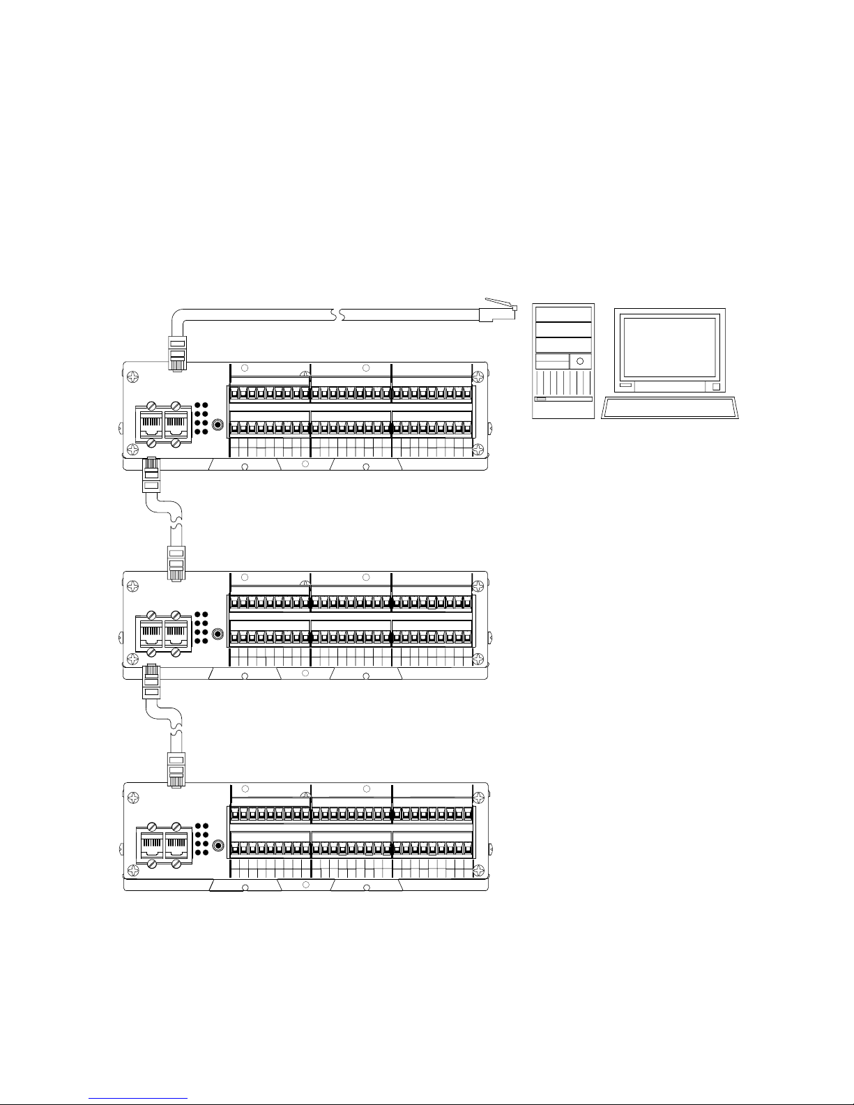
The unit includes two Ethernet ports for convenient cascaded network
connections as shown here. This is also useful for extending the network as
each segment may extend up to 100 meters.
Note that data collisions are still possible in the first two network segments
shown below, as these connections carry the data of more than one unit.
You can isolate each segment and prevent collisions using an external
Ethernet switch connected as shown in the diagram of the following page
(our recommended approach).
TIP: You can significantly enhance the EMI/RFI performance of your
network connections by using Category 5E STP cable (Shielded Twisted
Pair) cable. The use of shielded cable is strongly recommended for
installations in harsh industrial environments and/or in the presence of
strong electrical fields. For more information on cable, refer to the Cables &
Connectors section at the back of this manual.
CONNECTIONS
Network
EtherStax™ ES2163/2164 User’s Manual Modbus TCP/UDP/IP Analog Input
___________________________________________________________________
_______________________________________________________________________________________
Acromag, Inc. Tel:248-295-0880 Fax:248-624-9234 Email:sales@acromag.com http://www.acromag.com
19
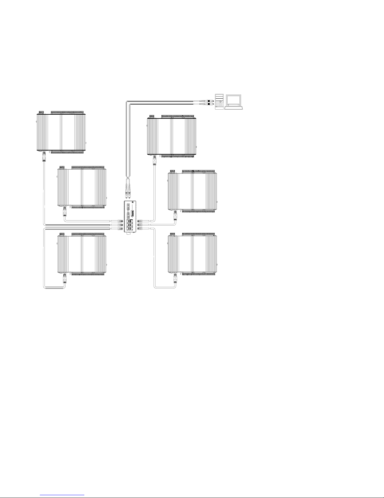
You can use an Ethernet switch or switching hub to build a network of
EtherStax units, similar to that shown below. The drawing depicts our
recommended approach to distributing I/O via switched Ethernet—that is,
one EtherStax unit is connected per switch port.
P1
P2
P4
P5
P7
P8
P3
P6
R.M.
P5
P7
P8
P6
RX RESET
FAULT
PWR2
RX
R.M.
TX PWR
P1
P3
FDX/
COL
P2
P4
TX
PWR1
LNK/
ACT
SC
EIS-408FX-M
Acromag
SC
I/O 1
I/O 6
I/O 2
I/O 4
I/O 5
I/O 3
ETHERNET
SWITCH
CROSSOVER
HOST PC
(OR PLC/DCS CONTROLLER)
LOCAL AREA NETWORK
NODES WIRED FOR SWITCHED
ETHERNET (ONE UNIT PER
SWITCH PORT) VIA COPPER
RJ45 CONNECTIONS.
UP TO 100M PER SEGMENT.
ACROMAG
EIS-408FX-M
REMOTE HOST
(NIC W/FIBER INSTALLED)
OR
NIC TO SC-TYPE FIBER
MEDIA CONVERTER
FIBER TO REMOTE HOST (UP TO 2KM)
RECOMMENDED CONNECTIONS
(SWITCHED ETHERNET)
The drawing above shows how to network-connect EtherStax units to an 8-
port Ethernet switch (such as Acromag Model EIS-408FX-M). Note that the
I/O LAN is distributed locally using copper/RJ45 cable connections (up to
100M per segment), and then connected to a remote (distant) host using
fiber cable. The copper connections may use standard or crossover cables,
as both the EtherStax unit and the Ethernet switch include automatic
crossover, but it is generally not considered good practice to use crossover
cables when connecting to an auto-crossing switch.
The switch shown above could be eliminated, if you were connecting to an
EtherStax Model ES2163/2164-1000, which includes one fiber port and one
standard RJ45 port. For example, you could use the fiber port built into the
EtherStax to connect to the distant host using fiber, then add an additional
EtherStax locally via its RJ45 port, similar to that shown on the next page.
However, the traffic of both units would still be concentrated in the main
trunk from the host, and this does not follow the key principle of switched
Ethernet, which seeks to suppress CSMA/CD and prevent data collisions by
connecting only one device per switch port.
CONNECTIONS
Network
The drawing at left gives our
recommended approach to
making network connections to
the EtherStax via switched
Ethernet.
Here we show one EtherStax
unit connected per switch port.
Thus, each segment is limited
to the traffic of only one device
and no collisions are possible.
This provides the most
deterministic method of
network communication. Only
the segment between the host
and the switch carries the
traffic of multiple units and
collisions are still possible in
this segment.
Note that fiber connections
must be crossed over, as the
auto-crossing feature only
applies to copper connections.
OBSERVATION: The extra
copper port of any of these
units can optionally connect to
other network devices, but the
resulting concentrated traffic in
the upstream network segment
would violate the goal of
switched Ethernet which is to
limit the traffic on each
segment to the traffic of one
device, suppressing
CSMA/CD. This is generally
not a problem for a small
number of cascaded units.
For many cascaded nodes, it
is good practice for the
upstream network segment to
use a data rate that is 10x the
data rate of the downstream
nodes, otherwise careful
attention must be paid to
limiting the number of Ethernet
devices that traffic on this
segment.

EtherStax™ ES2163/2164 User’s Manual Modbus TCP/UDP/IP Analog Input
__________________________________________________________________
_______________________________________________________________________________________
Acromag, Inc. Tel:248-295-0880 Fax:248-624-9234 Email:sales@acromag.com http://www.acromag.com
20
Unfortunately, you cannot avoid concentrated traffic in the main host
segment, even with a switch. As such, this aggregate path is usually chosen
to operate at a higher data rate than the downstream segments. With the
traffic of many Ethernet devices, this would mean that if the main trunk runs
at 100MB, then the downstream nodes should operate at 10MB (or 100MB if
the main trunk was 1Gbps, which the switch of the EtherStax units does not
support). If you cannot easily increase the bandwidth of this segment, then
you should be careful to limit the traffic in this shared segment by limiting the
total number of Ethernet devices connected downstream.
SC
CROSSOVER
SC
HOST PC
ETHERSTAX HAS
AN ETHERNET
SWITCH BUILT-IN
MODEL ES2113-1000
(One Copper Port and one Fiber Port)
CASCADED
COPPER
CONNECTION
I/O 2
I/O 1
ALTERNATE CONNECTIONS
(SWITCHED ETHERNET WITH
TWO NODES)
REMOTE HOST
(NIC W/FIBER INSTALLED)
OR
NIC TO SC-TYPE FIBER
MEDIA CONVERTER
CAUTION: YOU SHOULD LIMIT THE NUMBER
OF CASCADED CONNECTIONS, AS THIS WILL
INCREASE THE CONCENTRATION OF TRAFFIC
IN THE CUT-THROUGH PATH WITH THIS
CONNECTION.
FIBER TO REMOTE HOST (UP TO 2KM)
LOCAL AREA NETWORK
NODES WIRED FOR SWITCHED
ETHERNET (ONE UNIT PER
SWITCH PORT) VIA COPPER
RJ45 CONNECTIONS.
UP TO 100M PER SEGMENT.
NOTE:
I/O 1 IS THE ES2113-1000,
WHICH HAS ONE PORT OF
FIBER, AND ONE PORT OF
COPPER.
ALL ETHERSTAX UNITS HAVE
A BUILT-IN ETHERNET SWITCH.
THUS, THIS CONNECTION RETAINS
THE BENEFITS OF SWITCHED
ETHERNET FOR TWO UNITS.
For optimum performance, the ideal recommended approach is to utilize an
external Ethernet switch and connect no more than one Ethernet device per
switch port—this is what is referred to as switched Ethernet. Connection in
this manner avoids the negative effects of concentrated traffic and
suppresses the need for collision detection. This effectively allows a
segment to operate in full-duplex at the fastest possible speed. Thus, the
throughput of 100M at half-duplex, can effectively approach 200MB when
operating at full-duplex for switched Ethernet.
Although the connection shown above still retains the benefit of switched
Ethernet without utilizing an external switch, it really only applies to the first
two nodes. If you wanted to connect more than two nodes, but still retain the
benefits of switched Ethernet, you would have to utilize an external Ethernet
switch and connect one EtherStax unit per switch port.
CONNECTIONS
Network
The drawing at right gives an
alternate method for
connecting to a remote host,
while still retaining the benefit
of switched Ethernet between
two nodes.
This still adheres to the
principles of switched Ethernet
because the network ports of
the EtherStax are provided by
an internal 3-port Ethernet
switch.
However, note that the fiber
connection carries the traffic of
both units and this segment is
subject to data collisions.
Likewise, if you add a third
unit, I/O3, cascaded from I/O
2, then the first copper
segment carries the burden of
the traffic of I/O 2 and I/O 3.
This would not promote the
benefit of switched Ethernet in
this segment where we
attempt to limit the traffic on a
switched segment to a single
device and suppress the need
for CSMA/CD.
WARNING: Never use the
EtherStax as a bridge device
connected in series within your
enterprise LAN, as the effect
of concentrated traffic in the
shared segment could inhibit
communication to/from your
EtherStax unit.
Ideally, the shared segment
link that carries the
concentrated 100Mbps traffic
should operate at a higher
data rate, like 1Gbps, which
this switch does not support
.
This manual suits for next models
1
Table of contents
Other Acromag Adapter manuals

Popular Adapter manuals by other brands


Toa
Toa NF-CS1 Read me first

D-Link
D-Link XTREME N DUAL BAND USB ADAPTER DWA-160 Quick installation guide

Olympus
Olympus xD-Picture Card MAUSB-300 Start guide

BeachTek
BeachTek DXA-5D operating instructions

TRENDnet
TRENDnet TEW-604UB Quick installation guide

Rosewill
Rosewill RNX-AC1200PCE Quick installation guide