Acromag SP236-0600 User manual
USB Programmable, DIN Rail Mount,
Passive I/O DC Current/Voltage Input Splitter with
Dual Isolated 2-Wire 4-20mA Transmitter Outputs
Model SP236-0600, DC Current & Low DC Voltage Input
Model SP237-0600, DC ±1V/±10V Medium Voltage Input
Model SP238-0600, DC ±15V/±150V High Voltage Input
USER’S MANUAL
ACROMAG INCORPORATED Tel: (248) 295-0880
30765 South Wixom Road Fax: (248) 624-9234
Copyright 2018, Acromag, Inc., Printed in the USA.
Data and specifications are subject to change without notice. 8501105B

Model SP23x-0600
Two-Wire DC I/V Dual Output Transmitters
w/USB
Acromag, Inc. Tel: 248-295-0880 - 2 -
http://www.acromag.com
- 2 -
https://www.acromag.com
Table of Contents
GETTING STARTED
DESCRIPTION.......................................................................................................4
Key Features........................................................................................................................4
Application ..........................................................................................................................5
Mechanical Dimensions .......................................................................................................5
DIN Rail Mounting & Removal..............................................................................................6
ELECTRICAL CONNECTIONS ............................................................................ 7
Input Connections................................................................................................................7
Output/Power Connections .................................................................................................9
Earth Ground Connections .................................................................................................12
USB Connections................................................................................................................13
CONFIGURATION SOFTWARE...................................................................... 14
Quick Overview –Android Reconfiguration........................................................................14
Quick Overview –Windows ...............................................................................................20
OPERATION STEP-BY-STEP.......................................................................... 22
Connections.......................................................................................................................22
Configuration.....................................................................................................................23
Calibration (Optional) ........................................................................................................26
BLOCK DIAGRAM ............................................................................................. 28
How It Works.....................................................................................................................28
TROUBLESHOOTING....................................................................................... 29
Diagnostics Table...............................................................................................................29
Service & Repair Assistance ...............................................................................................31
ACCESSORIES .................................................................................................... 32
Software Interface Package................................................................................................32

Model SP23x-0600
Two-Wire DC I/V Dual Output Transmitters
w/USB
Acromag, Inc. Tel: 248-295-0880 - 3 -
http://www.acromag.com
- 3 -
https://www.acromag.com
USB Isolator.......................................................................................................................32
USB A-B Cable....................................................................................................................32
USB A-mini B Cable ............................................................................................................32
ACCESSORIES .................................................................................................... 33
USB OTG Cable ..................................................................................................................33
End Stops...........................................................................................................................33
SPECIFICATIONS .............................................................................................. 34
Model Numbers.................................................................................................................34
Input .................................................................................................................................34
Input…...............................................................................................................................37
Output...............................................................................................................................37
USB Interface.....................................................................................................................38
Enclosure & Physical ..........................................................................................................39
Environmental ...................................................................................................................40
Agency Approvals ..............................................................................................................41
Reliability Prediction..........................................................................................................42
Configuration Controls.......................................................................................................42
REVISION HISTORY ......................................................................................... 42
All trademarks are the property of their respective owners.
IMPORTANT SAFETY CONSIDERATIONS
You must consider the possible negative effects of power, wiring, component, sensor, or software failure in the design of
any type of control or monitoring system. This is very important where property loss or human life is involved. It is
important that you perform satisfactory overall system design and it is agreed between you and Acromag, that this is your
responsibility.
The information of this manual may change without notice. Acromag makes no warranty of any kind with regard to
this material, including, but not limited to, the implied warranties of merchantability and fitness for a particular
purpose. Further, Acromag assumes no responsibility for any errors that may appear in this manual and makes no
commitment to update, or keep current, the information contained in this manual. No part of this manual may be
copied or reproduced in any form without the prior written consent of Acromag, Inc.
This manual is for our 2-wire (loop-powered) SP200 model transmitters that convert a DC voltage or current input signal
to dual isolated current output loops. However, if your application requires dual output 4-wire transmitters (w/ separate
isolated DC power) that drive voltage/current outputs, please refer to similar SP300 series models. For thermocouple
input signals, please refer to our SP233 (2-wire loop-powered) and SP333 (4-wire) models.

Model SP23x-0600
Two-Wire DC I/V Dual Output Transmitters
w/USB
Acromag, Inc. Tel: 248-295-0880 - 4 -
http://www.acromag.com
- 4 -
https://www.acromag.com
GETTING STARTED
DESCRIPTION
Symbols on equipment:
Means “Refer to User’s Manual
(this manual) for additional
information”
Model SP23x-0600 transmitters are ANSI/ISA Type II transmitters with dual isolated
outputs, commonly referred to as signal splitters or repeaters. These units are
designed to interface with a DC Current or DC voltage input signal, isolate the input,
and separately modulate two isolated 2-wire current loops proportional to the
input.
The SP236-0600 is designed for DC Current (0-20mA/4-20mA), and Low Voltage DC
(±0.5V/0-500mV) input. The SP237-0600 is designed for medium voltage DC signals
(±1V, ±5V, ±10V), and the SP238-0600 for large Voltage DC signals (±15V, ±75V,
±150V). All units are set up and calibrated using a wired USB connection to a
Windows-based PC running configuration software (Windows 7 and later versions
only), or an Android-based tablet or smartphone running our Agility mobile APP.
Units provide an adjustable input range, input isolation, and variable input filtering.
Key Features
•Digitally set up and calibrated via a wired USB connection to a Windows-
based personal computer, or a wired USB-OTG connection to an Android
tablet or smartphone.
•Thin 17.5mm wide enclosure for high-density DIN-rail mounting.
•Models support both process current input and DC voltage input. SP236 has
separate inputs for 0-20mA/4-20mA/0-11.17mA/±1mA, and ±0.5V/0-500mV.
SP237 has separate inputs for ranges up to ±1V, and ±10V. SP238 has
separate inputs for high-level ranges up to ±15V, and ±150V.
•High measurement accuracy & linearity w/24-bit input & 16-bit output
conversion.
•Adjustable input range and adjustable output ranges. Input and outputs can
be scaled independently and the input may be scaled differently for each
output.
•Extra output connection supports optional sourced output wire termination.
•Variable input filter adjustment.
•Normal or reverse acting output.
•Very low loop burden with terminal voltage down to 7V.
•Convenient two-wire loop power with non-polarized output connections. The
input can be powered from either or both output loops and will function as a
simple isolated transmitter or a signal splitter.
•Namur compliant loop current.
•Wide ambient temperature operation.
•Thoroughly tested and hardened for harsh environments.
•CE Approved & includes UL/cUL Class 1, Division 2 Approvals.
•FCC Conformity Class B.
•ATEX Certified for Explosive Atmospheres.
II 3 G Ex nA IIC T4 Gc -40oC ≤Ta ≤+80oC
DEMKO 18 ATEX 2086X IECEx UL 18.0092X
!

Model SP23x-0600
Two-Wire DC I/V Dual Output Transmitters
w/USB
Acromag, Inc. Tel: 248-295-0880 - 5 -
http://www.acromag.com
- 5 -
https://www.acromag.com
Application
For additional information on
these devices and related topics,
please visit our web site at
www.acromag.com and download
our whitepaper 8500-904,
Introduction to Two-Wire
Transmitters.
These transmitters are designed for high-density mounting on T-type DIN rails.
Units may be mounted side-by-side on 17.5mm centers.
Models isolate current or voltage input signals and can mate with grounded or non-
grounded sensors. They provide dual isolated 4-20mA output current loops that are
linear with sensor current or voltage. A unique feature of these splitters is that the
input and outputs can each be scaled independently, and you may even scale the
input differently for each output.
The output signal is transmitted via dual two-wire, 4-20mA current loops. The two-
wire current signals can be transmitted over long distances with high noise
immunity. Its inherent live-zero 4mA offset current offers built-in output fault
detection, should an output wire break. An extra connection screw at each output
allow it to be optionally wired for a “sourced” 4-20mA output configuration (see
Optional Output Wiring).
Mechanical Dimensions
Units may be mounted to 35mm
“T” type DIN rail (35mm, type
EN50022), and side-by-side on
0.69-inch centers.
WARNING: IEC Safety Standards
may require that this device be
mounted within an approved
metal enclosure or sub-system,
particularly for applications with
exposure to voltages greater than
or equal to 75VDC or 50VAC.
Model SP23x-0600
Two-Wire DC I/V Dual Output Transmitters
w/USB
Acromag, Inc. Tel: 248-295-0880 - 6 -
http://www.acromag.com
- 6 -
https://www.acromag.com
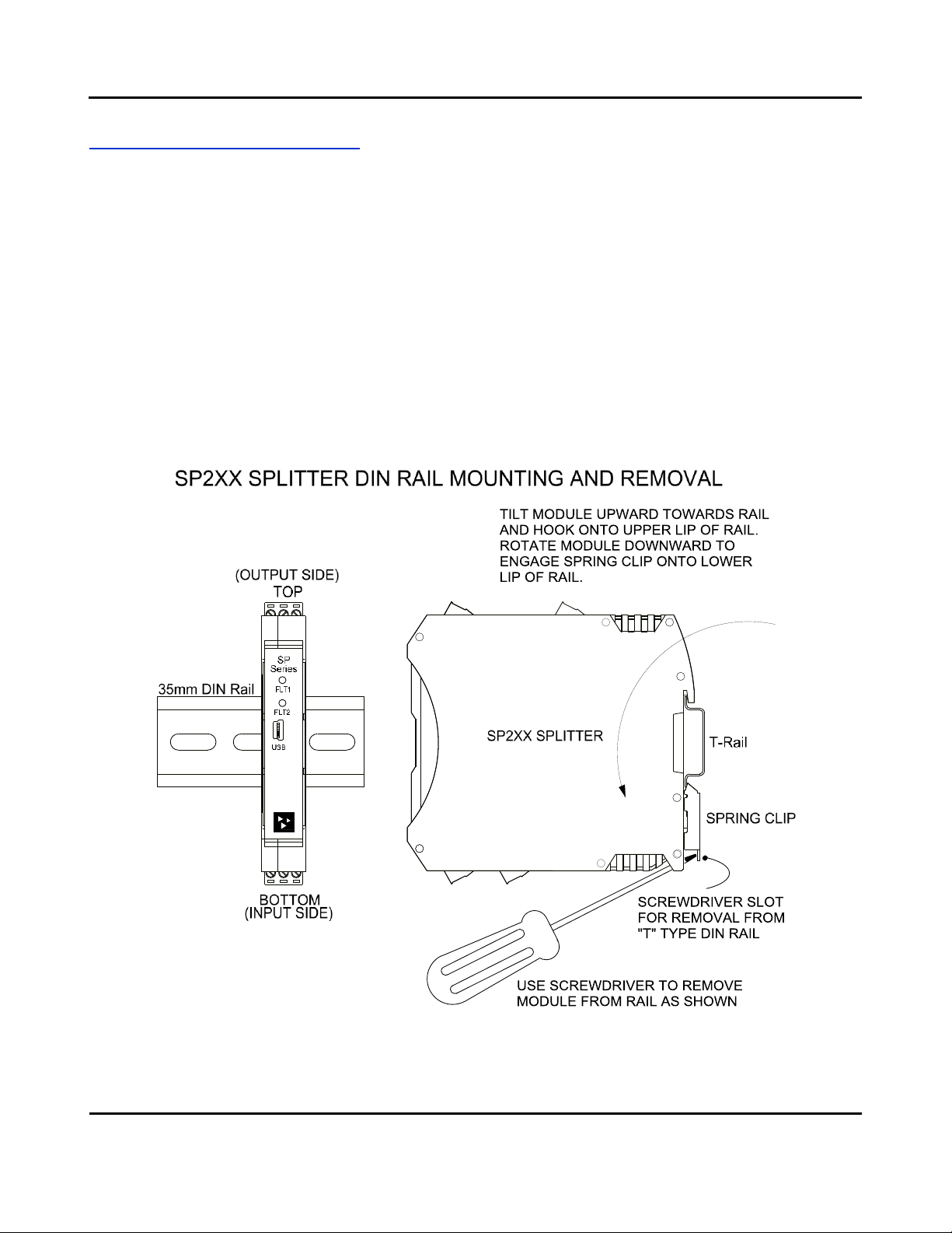
DIN Rail Mounting & Removal
Refer to the following figure for attaching and removing a unit from the DIN rail. A
spring-loaded DIN clip is located on the input side bottom. The opposite rounded
edge at the bottom of the output side allows you to tilt the unit upward to lift it
from the rail while prying the spring clip back with a screwdriver. To attach the
module to T-type DIN rail, angle the top of the unit towards the rail and place the
top groove of the module over the upper lip of the DIN rail. Firmly push the unit
downward towards the rail until it snaps into place. To remove it from the DIN rail,
first separate the input terminal blocks from the bottom side of the module to
create a clearance to the DIN mounting area. You can use a screwdriver to pry the
pluggable terminals out of their sockets. Next, while holding the module in place
from above, insert a screwdriver into the lower path of the bottom of the module to
the DIN rail clip and use it as a lever to force the DIN rail spring clip down while
pulling the bottom of the module outward until it disengages from the rail. Then
simply lift it from the rail.

Model SP23x-0600
Two-Wire DC I/V Dual Output Transmitters
w/USB
Acromag, Inc. Tel: 248-295-0880 - 7 -
http://www.acromag.com
- 7 -
https://www.acromag.com
ELECTRICAL CONNECTIONS
WARNING –EXPLOSION HAZARD –Do not disconnect equipment unless power has
been removed or the area is known to be non-hazardous.
WARNING –EXPLOSION HAZARD –Substitution of any components may impair
suitability for Class I, Division 2.
WARNING –EXPLOSION HAZARD –The area must be known to be non-hazardous
before servicing/replacing the unit and before installing.
Wire terminals can accommodate 14–26 AWG (2.08–0.13mm2) solid or stranded
wire with a minimum temperature rating of 85oC. Input wiring may be shielded or
unshielded type. Ideally, output wires should be twisted pair, or shielded twisted
pair. Terminals are pluggable and can be removed from their sockets by prying
outward from the top with a flat-head screwdriver blade. These models support two
separate input ranges at TB1 and TB2. Only one input may drive the current
outputs at one time. Strip back wire insulation 0.25-inch on each lead and insert
the wire ends into the cage clamp connector of the terminal block. Use a
screwdriver to tighten the screw by turning it in a clockwise direction to secure the
wire (0.5-0.6Nm torque). Since common mode voltages can exist on signal wiring,
adequate wire insulation should be used and proper wiring practices followed. As a
rule, output wires are normally separated from input wiring for safety, as well as for
low noise pickup.
Important –End Stops: For hazardous location installations (Class I, Division 2 or
ATEX / IECEx Zone 2), it should utilize two end stops (like Acromag 1027-222) to help
secure modules to the DIN rail (not shown).
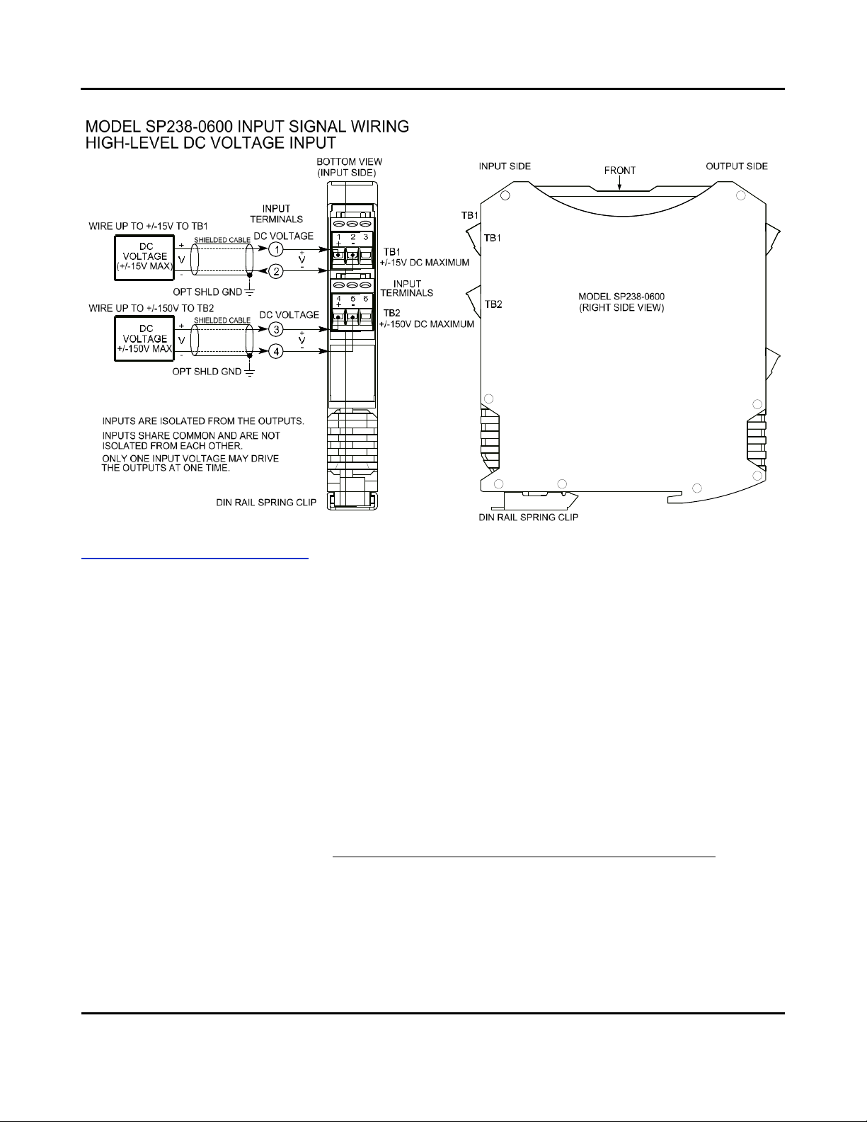
Input Connections
Sensor wires are wired directly to transmitter input terminals at the bottom of the
module (the spring-loaded DIN clip side), as shown in the connection drawing
below. Observe proper polarity when making input connections.
•Transmitter input signal is isolated from each output.One or both
outputs may power the input allowing it to be used as a single channel
transmitter or signal splitter.
•Only one input, current or voltage, may drive the outputs at one time.
•The input may be rescaled differently for each output.
•SP236 DC Current is wired to the upper terminal block TB1 and DC
Voltage is wired to the lower terminal block TB2.
•SP237 ±1V DC maximum is wired to the upper terminal TB1 and ±10V DC
maximum is wired to the lower terminal block TB2.
•SP238 ±15V DC maximum is wired to the upper terminal TB1 and ±150V
DC maximum is wired to the lower terminal block TB2.
•Inputs are polarized ±. The positive input is on the left and labeled “+”,
and the negative input is to its right. Observe proper polarity. See
connection figures below.
!

Model SP23x-0600
Two-Wire DC I/V Dual Output Transmitters
w/USB
Acromag, Inc. Tel: 248-295-0880 - 8 -
http://www.acromag.com
- 8 -
https://www.acromag.com
Model SP23x-0600
Two-Wire DC I/V Dual Output Transmitters
w/USB
Acromag, Inc. Tel: 248-295-0880 - 9 -
http://www.acromag.com
- 9 -
https://www.acromag.com
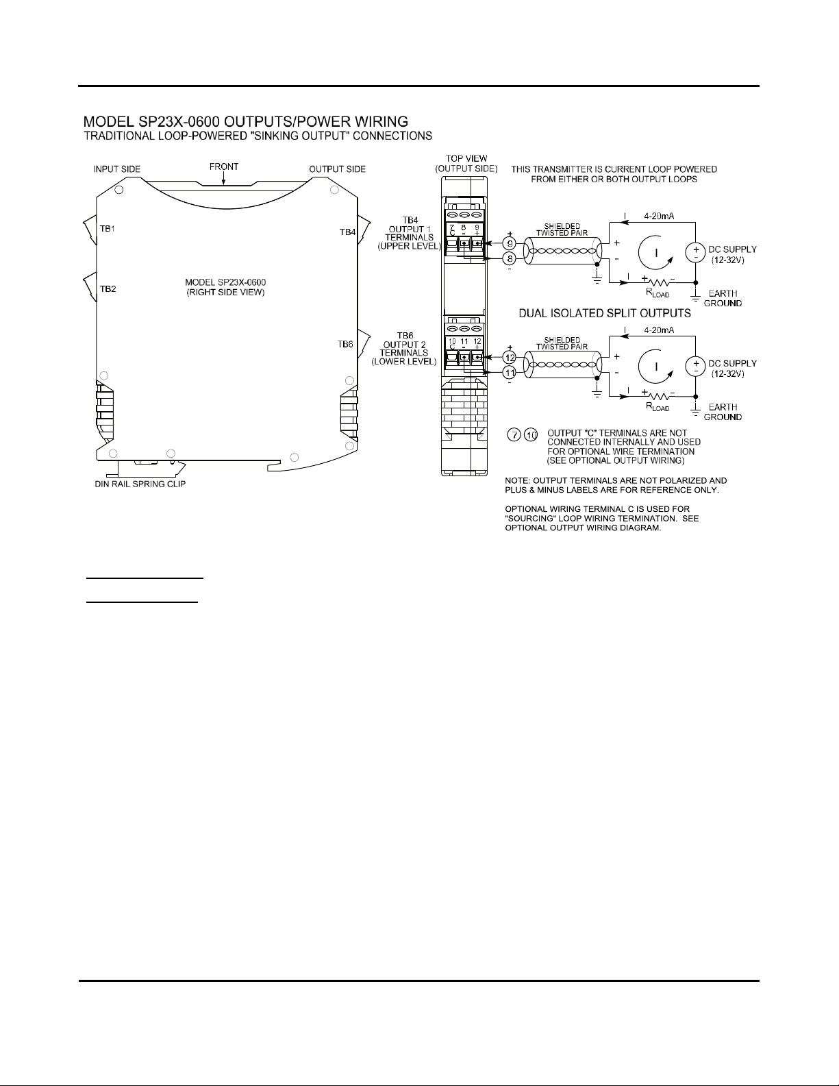
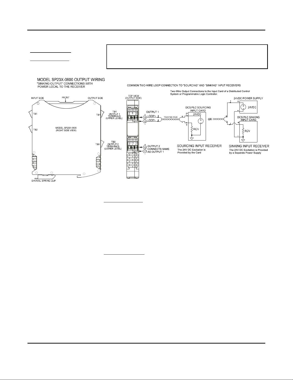
Output/Power Connections
This transmitter has dual ANSI/ISA Type 2 outputs in which the unit’s power and
output signal share the same two leads, and each splitter output has a “floating”
connection with respect to earth ground. Connect a DC power supply and load in
series in each of the two-wire output loops as shown in the drawings that follow.
•Passive output connections are not polarized. The output + and –designations
are for reference only with current normally input to Output+ and returned via
Output- (current sinking). Either or both output loops may power the input.
•Loop supply voltages should be from 7-32V DC with the minimum voltage level
adjusted to supply over-range current to the loop load, load plus 7V MIN across
the transmitter, plus any transmission line drop.
•Variation in power supply voltage between the 7V minimum required and 32V
maximum allowed, has negligible effect on transmitter accuracy.
•Variation in load resistance has negligible effect on output accuracy if the loop
supply voltage level is set correctly for the load resistance.
•Note the traditional placement of earth ground in the current loop. Output
Earth ground is normally applied at the loop power supply minus terminal.
Each 2-wire transmitter output varies off this ground by the voltage drop in the
load resistance and lead-wire of the loop.
Model SP23x-0600
Two-Wire DC I/V Dual Output Transmitters
w/USB
Acromag, Inc. Tel: 248-295-0880 - 10 -
http://www.acromag.com
- 10 -
https://www.acromag.com
Output/Power
Connections…
The traditional loop-powered 2-wire “sinking” output connections are shown above.
Shielded twisted-pair wiring is often used at the outputs to connect the longest
distance between the field transmitter and the remote receivers as shown. Each
output of this transmitter is isolated and fluctuates relative to earth ground by the
voltage drop in the output load and connection wire. This makes it flexible in the
way it connects to various “Receiver” devices.
In most installations, the output loop power supply will be local to either the
transmitter, or local to the remote receiver of the loop. Common receiver devices
may include the input channel of a Programmable Logic Controller (PLC), a
Distributed Control System (DCS), or a panel meter. Some receiver devices already
provide excitation for the transmitter loop and these are referred to as “sourcing
inputs”. Other receivers that do not provide loop excitation are referred to as
“sinking” inputs, and these will require that a separate power supply connect within
the loop. These types of receivers are depicted in the figures on the next two pages
Model SP23x-0600
Two-Wire DC I/V Dual Output Transmitters
w/USB
Acromag, Inc. Tel: 248-295-0880 - 11 -
http://www.acromag.com
- 11 -
https://www.acromag.com
Output/Power
Connections…
WARNING: For compliance to applicable safety and performance standards,
the use of twisted pair output wiring is recommended. Failure to adhere to
sound wiring and grounding practices as instructed may compromise safety,
performance, and possibly damage the unit.
TIP - Ripple & Noise: Place additional capacitance at the load to help reduce the
60Hz/120Hz ripple sometimes present in industrial applications. For large 60Hz
ripple, connect an external 1uF or larger capacitor directly across the load to reduce
excess ripple. For sensitive applications with high-speed acquisition at the load,
high frequency noise may be reduced significantly by placing a 0.1uF or 0.01uF
capacitor directly across the load, and as close to the load as possible (this may also
raise RF immunity).
TIP - Inductive Loads: If either two-wire current loops include a highly inductive
load (such as an I/P current-to-pressure transducer), this may reduce output
stability. In this case, place a 0.1uF capacitor directly across the inductive load(s)
and this will typically cure the problem.
Model SP23x-0600
Two-Wire DC I/V Dual Output Transmitters
w/USB
Acromag, Inc. Tel: 248-295-0880 - 12 -
http://www.acromag.com
- 12 -
https://www.acromag.com
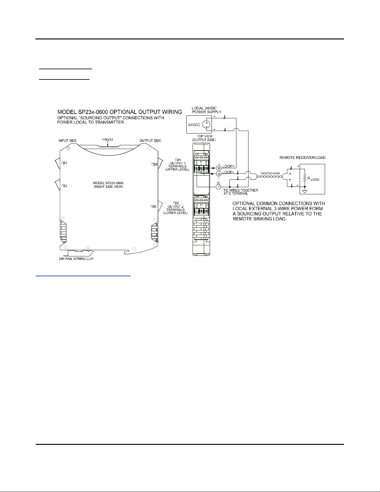
Output/Power
Connections…
This model includes an extra termination screw at each output marked “C” which is
intended to provide a convenient tie point for a “sourcing” wiring variation as
shown below. The C terminals do not connect to the internal circuit. Use of this
terminal in your wiring scheme allows you to connect external power local to the
transmitter and form a “sourcing” entity from this “sinking” output as shown below.
Earth Ground Connections
IMPORTANT: A USB isolator is
recommended when configuring
or calibrating a unit to avoid the
ground loop that occurs if your
input signal is also earth grounded
(A PC commonly ties earth ground
to its USB port signal and shield
ground, which is held in common
to the input circuit ground of this
transmitter).
The unit housing is plastic and does not require an earth ground connection to
itself. If the module is mounted in a metal housing, an earth ground wire
connection to that metal housing’s ground terminal (green screw) is usually
required using suitable wire per applicable codes. As a rule of good practice,
isolated circuits are normally earth grounded at one point. See the Electrical
Connections Drawing for Output/Power connections and note the traditional
position of earth ground for a two-wire output current loop. That is, earth ground is
normally applied at the output loop power minus terminal and in common with the
loop load or loop receiver minus. The Type II transmitter output terminals will have
a “floating”connection relative to earth ground and their potential varies with the
voltage drop in the load and connection wire. Circuits wired to isolated analog
inputs should be earth grounded as reflected in their input connection diagram.
Ground connections noted are recommended for best results and help protect the
unit and its isolated circuitry by giving it a low impedance path to ground for
shunting destructive transient energy away from sensitive module circuitry.
Respect the traditional position of earth ground in a two-wire current loop and
avoid inadvertent connections to earth ground at other points in the same loop,
which would drive ground loops and negatively affect operation.

Model SP23x-0600
Two-Wire DC I/V Dual Output Transmitters
w/USB
Acromag, Inc. Tel: 248-295-0880 - 13 -
http://www.acromag.com
- 13 -
https://www.acromag.com
USB Connections
Splitter is set up, configured, & calibrated via configuration software that runs on a
Windows-based PC connected via USB (Windows 7 or later required), or a USB
connection to a compatible Android-based tablet or smartphone with our Agility
mobile APP installed. Refer to the drawing below to connect your PC or laptop to
the splitter for reconfiguration and calibration using this software (the optional
connection to an Android smartphone or tablet would typically not require the use
of an isolator, because those devices are battery powered).
WARNING: The intent of mating
USB with this transmitter is so that
it can be conveniently set up and
calibrated in a safe area, then
installed in the field which may be
in a hazardous area. Do not
attempt to connect a PC or laptop
to this unit while installed in a
hazardous area, as USB energy
levels could ignite explosive gases
or particles in the air.
•USB Signal Isolation is Required (See Below) - You may use Acromag model
USB-ISOLATOR to isolate your USB port, or you can optionally use another USB
signal isolator that supports USB Full Speed operation (12Mbps).
•Configuration Requires USB and Loop Power - This transmitter draws power
from both the current loop and from USB during set up.
IMPORTANT: USB logic signals to the unit are referenced to the potential of its
internal signal ground. This ground is held in common with the USB ground and
shield ground. The potential of a transmitter’s current output pin (output minus)
relative to earth ground varies with the load current and resistance (net IR drop).
Without isolation, IR drop would drive a potential difference between the normally
grounded current loop and grounded USB connection at the PC, causing a ground
loop that would inhibit set up & calibration, or may even damage the transmitter. It
is recommended you use an isolated USB connection. Alternatively, you could avoid
using an isolator if a battery powered laptop was used to connect to the
transmitter, and the laptop has no earth ground connection, either directly or via a
connected peripheral.
!
Note: Output/Power to Transmitter must
be applied before USB connection
(See Output/Power Connections).
Model SP23x-0600
Two-Wire DC I/V Dual Output Transmitters
w/USB
Acromag, Inc. Tel: 248-295-0880 - 14 -
http://www.acromag.com
- 14 -
https://www.acromag.com
CONFIGURATION SOFTWARE
Quick Overview –Android Reconfiguration
This splitter can be configured & calibrated via the
Acromag Agility™ Config Tool App. This software app can
be downloaded free of charge from the Google Play store
at play.google.com and is compatible with Android devices
that use Ice Cream Sandwich (4.0) or later OS.
To connect to this splitter, a USB OTG (On-The-Go) cable (Acromag 5028-
565) and USB A to Mini-B cable (Acromag 4001-113) are also required.
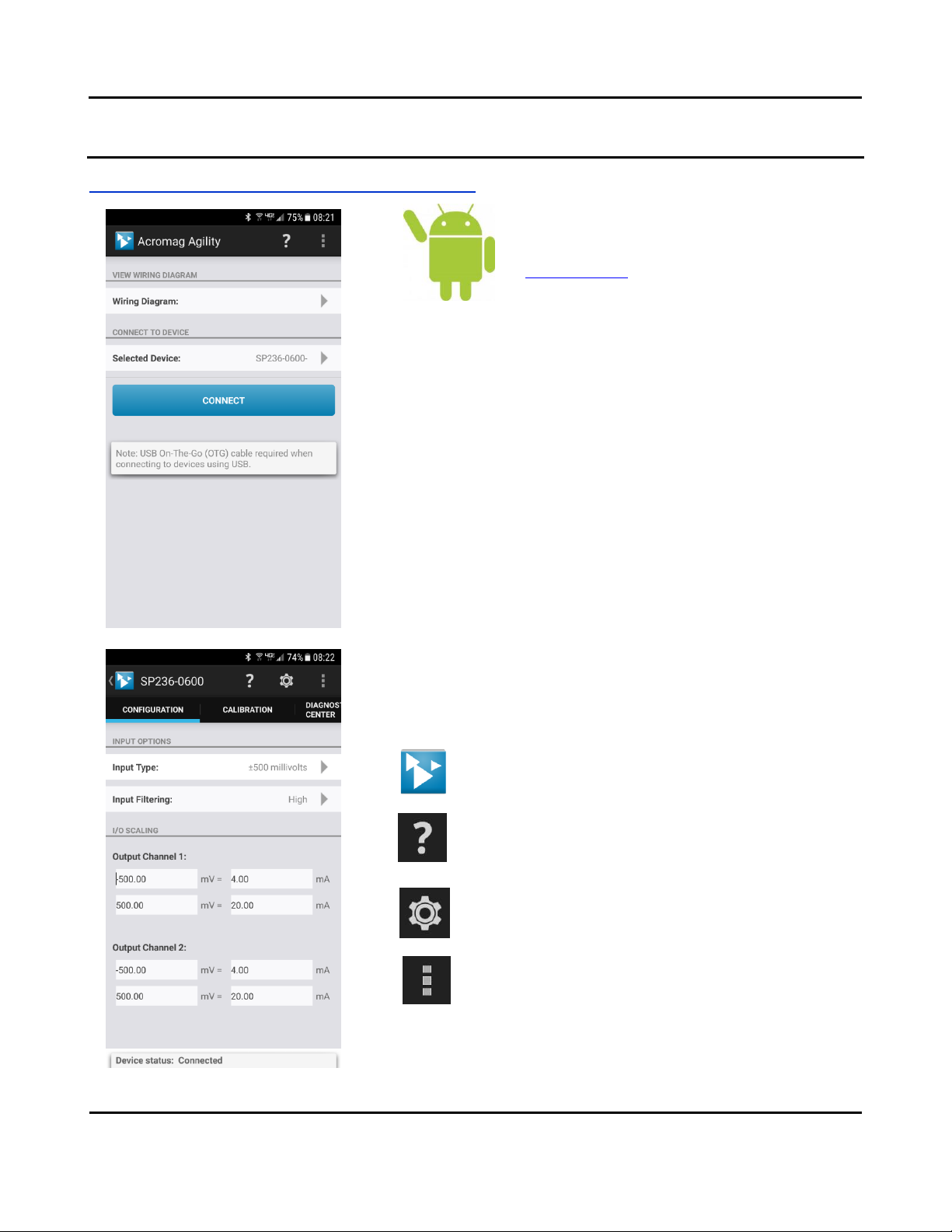
When you start the app, the initial Agility Connection screen at left will be
presented and if you have also connected a module using a USB OTG cable,
your module will be listed in the “Selected Device:” field of the Connection
screen as shown.
The ability to select other devices only applies to Bluetooth devices which
also utilize this app. Tap the [CONNECT] button to open communication
with the device indicated to the right of “Selected Device” and move to the
main portion of the app shown in the second screen at left. Note Android
requires user permission to access external hardware--If the Device List
displays “No Device Permission”, select the device and when prompted to
give permission to access the USB device, and tap [OK].
If you wish to view a wiring diagram for your splitter model, tap the arrow
next to “Wiring Diagram”. You may swipe left or right to view more
diagrams.
The main screen also has three icons across the top: an Acromag logo
w/connected model indicated, a question mark, a gear icon, and three
vertical dots. These icons access additional features of this software as
follows:
This icon located in the top left-hand corner of most app screens
serves as a Home button, which when tapped will return you to
the Connection page of the app from subsequent pages.
Tapping the question mark will access a Self-Test utility useful for
testing your device connection.
Tapping the Gear/Settings icon will access a Utility Page to do a
device Reboot, Reset Factory Calibration, or restore factory
Settings.
Tapping this icon will return “About” & “Contact Acromag”
Information.
A short description of what each icon does follows:
Model SP23x-0600
Two-Wire DC I/V Dual Output Transmitters
w/USB
Acromag, Inc. Tel: 248-295-0880 - 15 -
http://www.acromag.com
- 15 -
https://www.acromag.com
Quick Overview –Android Reconfiguration...continued
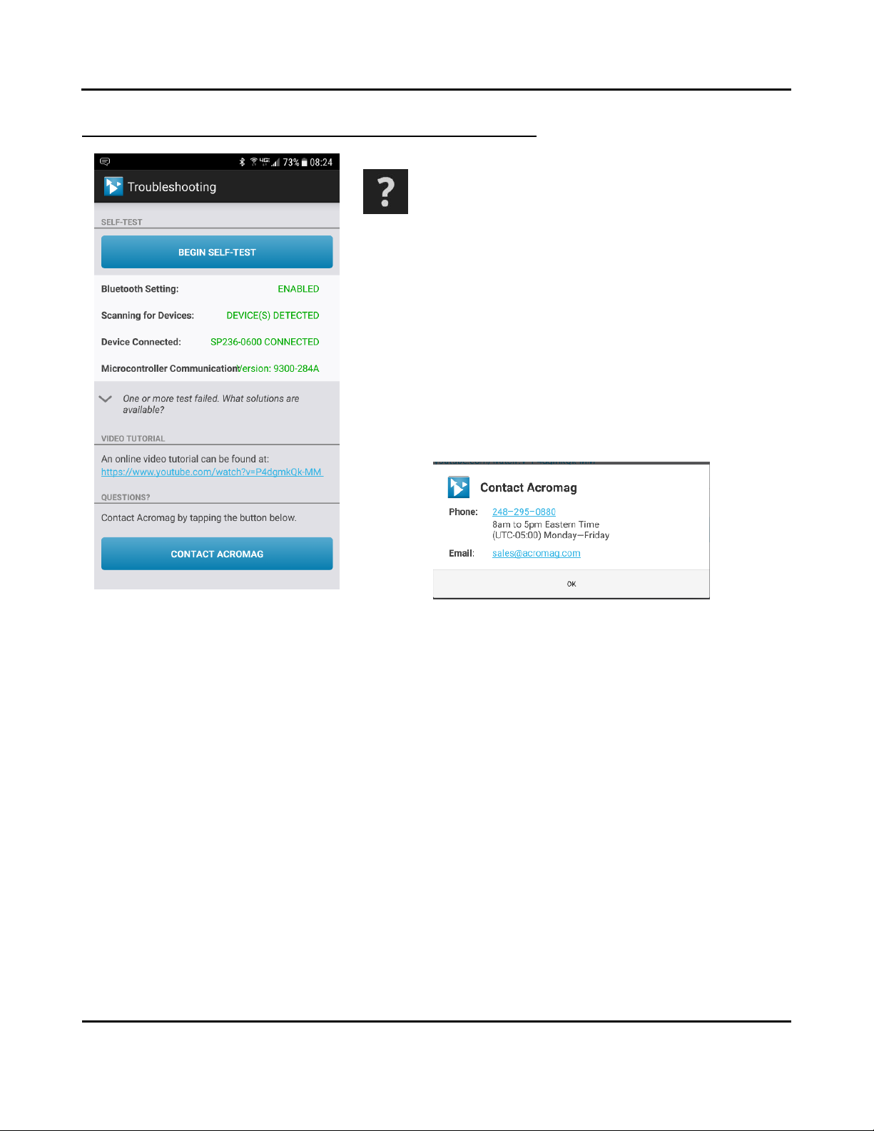
The HELP area of the application invokes a Self-Test feature that
can be used to determine if your smart phone or tablet has its
Bluetooth wireless technology enabled (useful for uB applications),
whether any modules can be detected by rescanning, whether a device is
connected, and whether the microcontroller of the connected module is
operational. You simply tap [BEGIN SELF-TEST] to perform the diagnostic
exchange and review the results returned. If one or more tests indicate
Failed, you can also tap the down arrow message below the self-test report
to access additional information regarding failed tests. Optionally, you can
review an online video tutorial on working with the unit by tapping the Video
Tutorial URL line.
Or, if you wish to contact Acromag for assistance, you can tap the [CONTACT
ACROMAG] bar to obtain the phone and email information window shown
below for talking to Acromag directly (the same information is also obtained
via the menu dotted action bar icon and “Contact Acromag” selection).
You may also refer to the Troubleshooting Table in this manual which lists
common issues related to working with these splitters and some
recommended remedies.
Model SP23x-0600
Two-Wire DC I/V Dual Output Transmitters
w/USB
Acromag, Inc. Tel: 248-295-0880 - 16 -
http://www.acromag.com
- 16 -
https://www.acromag.com
Quick Overview –Android Reconfiguration...continued
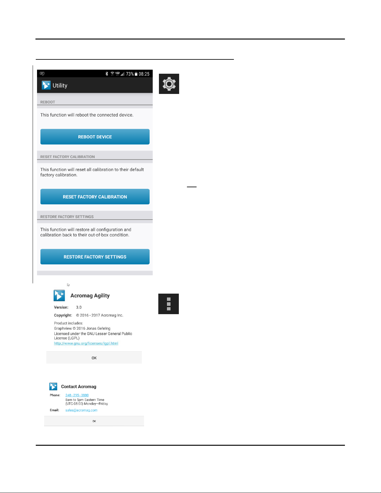
Tap the [Gear] icon in the Action bar to access the Utility Page
shown at left. Utilize these features if you if you encounter erratic
behavior with your splitter and need to get out of trouble, perhaps
if you ever inadvertently misconfigure or improperly calibrate a splitter.
You can tap [REBOOT DEVICE] on this page to reset/restart the connected
splitter, perhaps if it ever appears to freeze, or exhibits erratic operation.
This is akin to a power-on reset of the splitter.
You can tap [RESET FACTORY CALIBRATION] to get out of trouble if you ever
miscalibrate a splitter (this only affects splitter calibration).
You can tap [RESTORE FACTORY SETTINGS] to get out of trouble if you ever
misconfigure or miscalibrate a transmitter (this affects both splitter
calibration and configuration). You can also use this feature to de-
commission a splitter.
If you tap the right-most dotted Menu icon of the action bar at the
top right of your screen, you will get a selection menu for “About”
information on this software application, and “Contact Acromag”
for contact information, both shown at left
Below the icons of the top line are file three tabs: Configuration, Calibration,
and Diagnostic Center, each of which are described in the following pages.
Model SP23x-0600
Two-Wire DC I/V Dual Output Transmitters
w/USB
Acromag, Inc. Tel: 248-295-0880 - 17 -
http://www.acromag.com
- 17 -
https://www.acromag.com
Quick Overview –Android Reconfiguration...continued
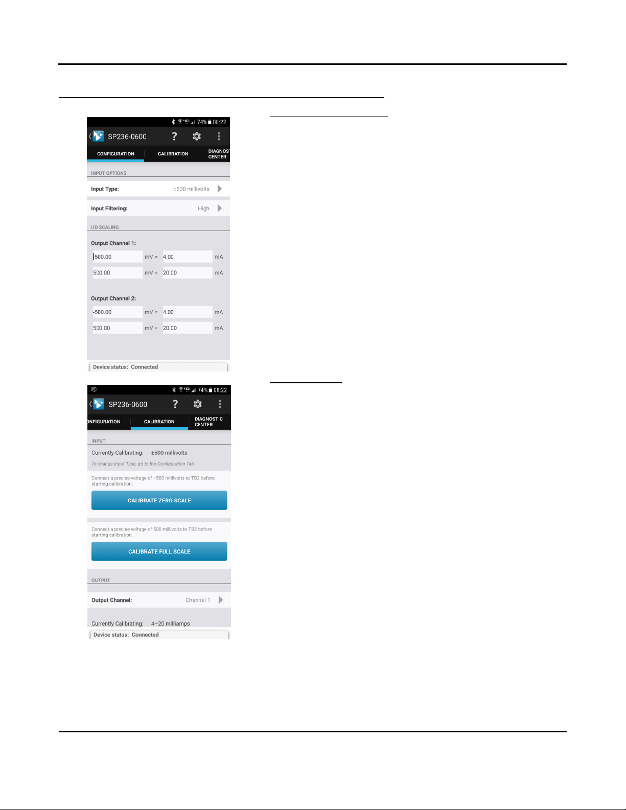
Input/Output Configuration
The I/O Configuration screen is shown at left and is used to Configure your
splitter Input and Output. You can set your input type/range, input digital
filtering level, rescale each output, and even scale the input differently for
each output via this screen.
Note that if your unit is connected when you select this tab, the app
automatically reads your splitter’s current I/O and scaling information and
displays it.
Likewise, changing any option on this page sends the changes to the
splitter immediately.
Note that the Device Status is indicated at the bottom of all pages and will
report if changes were sent successfully (Connected).
Input Calibration
If you have setup your unit and encounter excessive error, you may click
the Calibration tab to display the Calibration control screen shown at left,
which presents Input calibration controls first, followed by Output
calibration controls as you scroll down the page.
IMPORTANT: The splitter has already had its input & output channels
factory calibrated with high precision. If you attempt to recalibrate the
input or outputs, you may degrade its performance if done improperly, or
by using low grade equipment. Consider recalibration carefully.
The selected input range being calibrated is indicated at the top. The
software does not use your scaled sub-range zero to calibrate, but the
zero of the nominal range selected. Some sub-ranges have their
calibration extrapolated from the calibration of a larger native range.
Calibrate the largest native range first to keep its recalibration from over-
writing any sub-range calibration. These splitters have two input terminals
specific to input ranges--be sure to connect your input signal to the proper
terminals.
For input zero calibration, connect a precise input signal level for the zero
of your range, then tap the [CALIBRATE INPUT ZERO] button one time to
set the input ADC level to its input range zero (0%) point.
For full-scale calibration, connect a precise input signal level for the full-
scale value of your range, then tap [CALIBRATE INPUT FULL-SCALE] one
time to set the input ADC level to its input range full-scale (100%).
The device status at the bottom of the page will report if the calibration
was sent successfully.
Model SP23x-0600
Two-Wire DC I/V Dual Output Transmitters
w/USB
Acromag, Inc. Tel: 248-295-0880 - 18 -
http://www.acromag.com
- 18 -
https://www.acromag.com
Quick Overview –Android Reconfiguration...continued
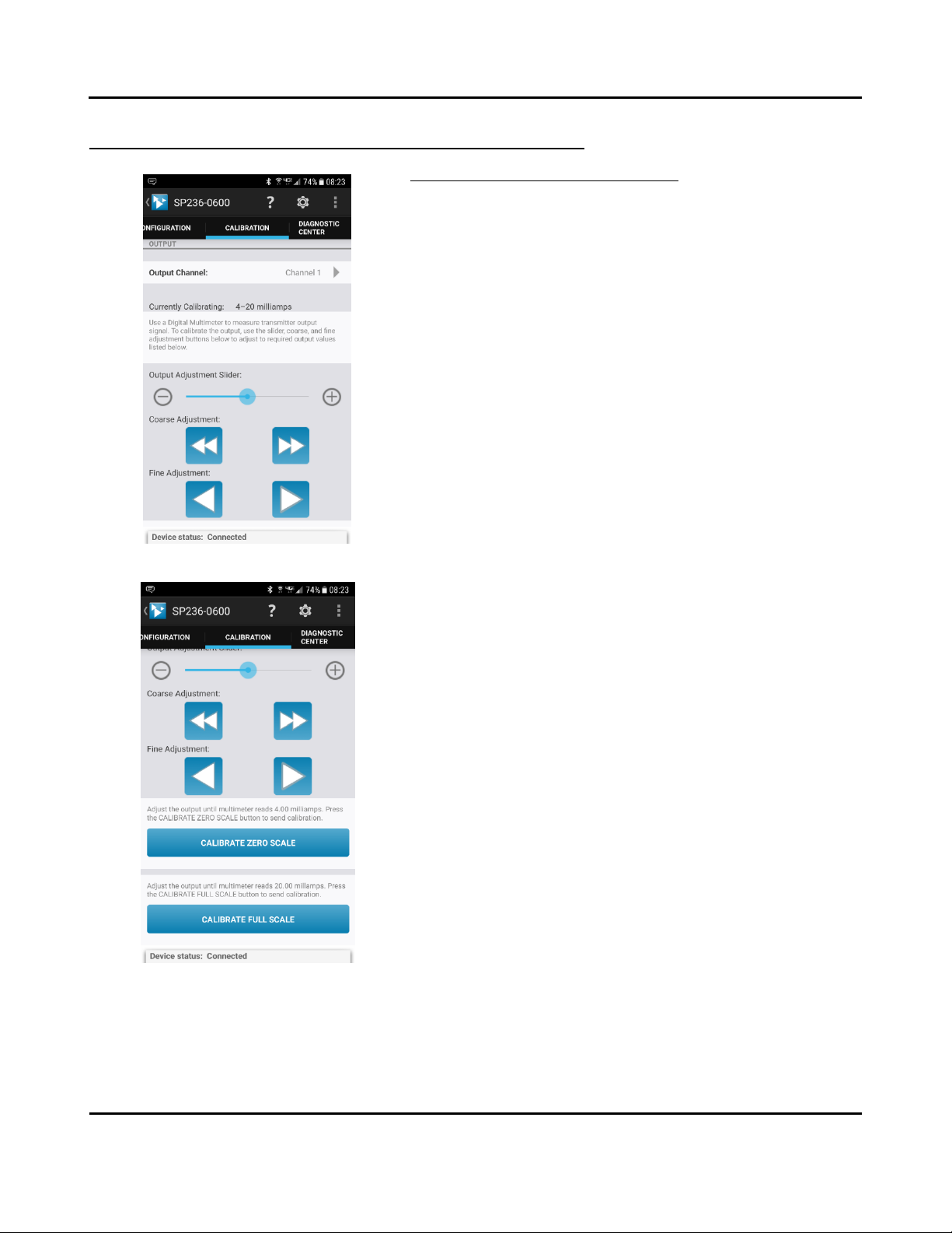
Output Calibration (Each of Two Outputs)
Scroll down the Calibration page to access the Output Calibration controls:
output channel selector, adjustment controls, and the [CALIBRATE
OUTPUT ZERO] and [CALIBRATE OUTPUT FULL-SCALE] buttons.
First select the Output channel to calibrate, and its output range will be
displayed along with some instructions on how to proceed.
For Output Zero calibration, use the output adjustment slider and the
coarse and fine adjustment controls to precisely set your output zero level
while precisely monitoring your output signal. Be sure to use a meter with
an accuracy at least 4x greater than the signal you are measuring for best
results. Note that the output adjustment controls temporarily remove
control of the output from the input to accomplish calibration (control of
the output level returns to the input signal after 30 seconds).
Once your output level is precisely set to its zero point (4.000mA for this
splitter), tap the [CALIBRATE OUTPUT ZERO] button one time to set the
output DAC level (its corresponding digital count) to correspond to the
zero (0%) of your output range.
For Full-Scale calibration, use the output adjustment slider and the coarse
and fine adjustment controls to precisely set your output full-scale level
while precisely monitoring your output signal. Be sure to use a meter with
an accuracy at least 4x greater than the signal you are measuring for best
results. Note that the output adjustment controls temporarily remove
control of the output from the input level to accomplish calibration
(control of the output level returns to the input signal after 30 seconds).
Once your output level is precisely set to its full-scale level (20.000mA for
this splitter), tap the [CALIBRATE OUTPUT FULL-SCALE] button one time to
set the output DAC level (its corresponding digital count) to correspond to
the full-scale (100%) level of the output range.
Repeat the Output Calibration of zero and full-scale for the second output
as required by selecting the opposite channel.
If following calibration, your output acts erratic or appears imprecise, you
may need to repeat input or output calibration, being very careful to take
accurate measurements and input correct signal levels. If you are
measuring voltage across an output load resistance to measure the
current level (recommended), make sure that you use exact resistance
when calculating the measured loop current. When rescaling I/O, make
sure that you have adequate I/O span, as “too-tight”input or output spans
will have diminished resolution and magnify error.

Model SP23x-0600
Two-Wire DC I/V Dual Output Transmitters
w/USB
Acromag, Inc. Tel: 248-295-0880 - 19 -
http://www.acromag.com
- 19 -
https://www.acromag.com
Quick Overview –Android Reconfiguration...continued
Performing Diagnostics (Polling & Trending the Input)
The Diagnostic Center screen tab is shown at left and used to verify input
(ADC) operation of your splitter. This page can be used to poll the input
data and display its value or graph the input data and trend its value. The
input type currently set is shown at the top of the screen (the input value,
not the scaled input value is polled).
Select the Indicator pointer to set your desired indication to “Digital”
(value) or “Graph” (trend).
You can specify a polling period to set the interval between polled
readings by over-typing the value in the Polling Period field.
Start polling the input by tapping the [START POLLING] button.
Clear the polling data by tapping [CLEAR DATA].
Check the “Save Data” box if you wish to log the polled values to a CSV
(Comma Separated Value) data file for reference.
Note the Communication Status of the device is indicated at the bottom of
the screen.

Model SP23x-0600
Two-Wire DC I/V Dual Output Transmitters
w/USB
Acromag, Inc. Tel: 248-295-0880 - 20 -
http://www.acromag.com
- 20 -
https://www.acromag.com
Quick Overview –Windows
Click “Open” to connect to the SP236-0600 and
your screen will look like:
For detailed configuration and calibration
procedures, see the Operation Step-By-Step
section of the Technical Reference on page 22 of
this manual.
In addition to the Android Agility mobile app, this splitter can be
optionally configured and calibrated via its USB Configuration
Software and a USB connection to a Windows PC or laptop. The
configuration software can be downloaded free of charge from our
web site at www.acromag.com. This software is also included on a
CDROM bundled with the Configuration Kit TT-SIP (see Accessories
section). For the SP236 model, look for program SP236Config.exe.
This software is compatible with Windows 7 or later versions of the
Windows operating system.
The initial configuration software screen for the SP238 model is
shown at left after clicking [Open] to open communication with a
connected module. The Configuration screen is divided into three
pages as follows: Communication Set up, I/O Config/Test, and
Calibration. A short description of each of these pages follows.
Communication Setup–First Select/Connect to Unit Here
•Select from connected transmitters using the Device scroll field
and Open/Close communications with them.
•Display the Model, Serial Number, and Manufacturer of the
connected transmitter, and report connection Status, or reset
a connected unit.
This section is used to select a connected transmitter, open/close
communications with it, or reset it. Device connection Status is
also indicated here, along with the connected transmitter’s Model,
Serial Number, & Manufacturer.
I/O Config/Test –Reconfigure and/or Test the Unit Here
•You can click the [Get I/O Config] button to retrieve the I/O
configuration of the currently connected transmitter.
•Select the Input Range for the model. For an SP236, you can
select current ranges ±20mA, 0-20mA, 4-20mA, 0-11.17mA, or
±1mA for inputs at TB1, or voltage ranges of ±0.5V and 0-
500mV for inputs at TB2.
•Set the level of digital filtering to High, Medium, or Low. Note
that the corresponding I/O response time will vary with filter
selection to 1200ms, 150ms, and 50ms respectively.
•View the unit’s communication status in the Status field.
•Use the I/O Scaling fields to specify the specific input range
endpoints that are to correspond to the 4mA and 20mA output
endpoints of each output. You can scale the input differently
for each output.
•You may set your own output range limits or enable
Namur limits that differentiate fault levels from over and
under range detents.
•Last, after making I/O changes, send your settings to the unit
by clicking the [Send I/O Config] button and following the on-
screen prompts.
This manual suits for next models
2
Table of contents
Other Acromag Cables And Connectors manuals


